


 Loading...
Elmo Motion Control
CANopen DSP 402
Implementation Guide
December 2004

Important Notice
This guide is delivered subject to the following conditions and restrictions:
This guide contains proprietary information belonging to Elmo Motion Control Ltd. Such information is supplied solely for the purpose of assisting users of SimplIQ servo drives in implementing CANopen networking.
The text and graphics included in this manual are for the purpose of illustration and reference only. The specifications on which they are based are subject to change without notice.
Information in this document is subject to change without notice. Corporate and individual names and data used in examples herein are fictitious unless otherwise noted.
Doc. No. MAN-CAN402IG
Copyright © 2003, 2004
Elmo Motion Control Ltd.
All rights reserved.
Revision History
Ver. 1.2 |
Dec. 2004 |
References to Harmonica changed to SimplIQ |
(MAN-CAN402IG) |
|
• New Profile Torque chapter |
|
|
|
• Chapter on interpolation was modified |
|
|
Ver. 1.1 |
Nov. 2003 |
mapping of the following objects modified: |
(MAN-CAN402IG) |
|
|
0x6040,0x6060,0x607A,0x6081,0x6082,0x6083,0x6084,0x6089, 0x60C1,0x60C2 |
|
Ver. 1.0 |
Sept. 2003 |
Initial Release |
(HARCREN1102) |
Elmo Motion Control Inc. |
Elmo Motion Control GmbH |
|
|||
1 Park Drive, Suite 12 |
Steinbeisstrasse 41 |
|
|||
Westford, MA |
01886 |
D-78056, Villingen-Schwenningen |
|
||
USA |
|
|
Germany |
|
|
Tel: |
+1 (978) |
399-0034 |
Tel: |
+49 (07720) 8577-60 |
www.elmomc.com |
Fax: |
+1 (978) |
399-0035 |
Fax: |
+49 (07720) 8577-70 |
|

CANopen DSP 402 Implementation Guide
MAN-CAN402IG (Ver. 1.2)
Contents |
|
|
1: Introduction ............................................................................................................................ |
1 |
|
1.1 |
Operating Principles......................................................................................................... |
1 |
1.2 |
Abbreviations and Terms................................................................................................. |
2 |
1.3 |
Elmo Documentation........................................................................................................ |
3 |
2: The DSP 402 Object Dictionary ........................................................................................... |
4 |
|
3: Emergencies ............................................................................................................................ |
9 |
|
4: Predefinition ........................................................................................................................... |
9 |
|
|
Object 0x1000: Device type .............................................................................................. |
9 |
|
Object 0x1001: Error register............................................................................................ |
9 |
5: Common Entries .................................................................................................................... |
12 |
|
5.1 |
Drive Error........................................................................................................................ |
12 |
|
Object 0x6007: Abort connection option code.............................................................. |
12 |
|
Object 0x603F: Error code .............................................................................................. |
13 |
5.2 |
Motor Data........................................................................................................................ |
13 |
|
Object 0x6402: Motor type.............................................................................................. |
13 |
|
Object 0x6403: Motor catalog number .......................................................................... |
14 |
|
Object 0x6404: Motor manufacturer.............................................................................. |
15 |
|
Object 0x6406: Motor calibration data .......................................................................... |
15 |
|
Object 0x6407: Motor service periods ........................................................................... |
16 |
5.3 |
Drive Data......................................................................................................................... |
16 |
|
Object 0x6502: Supported drive modes ........................................................................ |
17 |
|
Object 0x6504: Drive manufacturer............................................................................... |
17 |
|
Object 0x6505: http drive catalog address .................................................................... |
18 |
|
Object 0x60FD: Digital inputs........................................................................................ |
18 |
6: Device Control....................................................................................................................... |
20 |
|
6.1 |
Objects............................................................................................................................... |
20 |
|
Object 0x6040: Controlword .......................................................................................... |
26 |
|
Object 0x6041: Statusword ............................................................................................. |
28 |
6.2 |
Halt, Stop and Fault Objects ........................................................................................... |
31 |
|
Object 0x605A: Quick stop option code........................................................................ |
31 |
|
Object 0x605B: Shutdown option code ......................................................................... |
32 |
|
Object 0x605C: Disable operation option code ............................................................ |
33 |
|
Object 0x605D: Halt option code................................................................................... |
34 |
|
Object 0x605E: Fault reaction option code ................................................................... |
35 |
7: Modes of Operation .............................................................................................................. |
36 |
|
7.1 |
Functional Description .................................................................................................... |
36 |
7.2 |
Objects............................................................................................................................... |
36 |
|
Object 0x6060: Modes of operation ............................................................................... |
36 |
|
Object 0x6061: Modes of operation display.................................................................. |
37 |

CANopen DSP 402 Implementation Guide |
|
|
|
|
ii |
MAN-CAN402IG (Ver. 1.2) |
|
|
8: Factors ..................................................................................................................................... |
38 |
|
8.1 |
Relationship between Physical and Internal Units....................................................... |
38 |
8.2 |
Functions and Limits ....................................................................................................... |
38 |
8.3 |
Objects............................................................................................................................... |
39 |
|
Object 0x607E: Polarity................................................................................................... |
39 |
|
Object 0x6089: Position notation index......................................................................... |
40 |
|
Object 0x608A: Position dimension index .................................................................... |
40 |
|
Object 0x608B: Velocity notation index ........................................................................ |
41 |
|
Object 0x608C: Velocity dimension index .................................................................... |
42 |
|
Object 0x608D: Acceleration notation index ................................................................ |
42 |
|
Object 0x608E: Acceleration dimension index ............................................................. |
43 |
|
Object 0x608F: Position encoder resolution ................................................................. |
44 |
|
Object 0x6090: Velocity encoder resolution.................................................................. |
45 |
|
Object 0x6093: Position factor........................................................................................ |
46 |
|
Object 0x6094: Velocity encoder factor ......................................................................... |
47 |
|
Object 0x6095: Velocity factor 1..................................................................................... |
48 |
|
Object 0x6096: Velocity factor 2..................................................................................... |
49 |
|
Object 0x6097: Acceleration factor ................................................................................ |
51 |
9: Homing ................................................................................................................................... |
53 |
|
9.1 |
General Information ........................................................................................................ |
53 |
9.2 |
Objects............................................................................................................................... |
55 |
|
Object 0x607C: Home offset........................................................................................... |
55 |
|
Object 0x6098: Homing method .................................................................................... |
56 |
|
Object 0x6099: Homing speeds...................................................................................... |
57 |
|
Object 0x609A: Homing acceleration ............................................................................ |
58 |
9.3 |
Functional Description .................................................................................................... |
58 |
9.4 |
DSP 402 Homing Methods.............................................................................................. |
60 |
|
9.4.1 Method 1: Homing on the negative limit switch and index pulse................. |
60 |
|
9.4.2 Method 2: Homing on the positive limit switch and index pulse.................. |
60 |
|
9.4.3 Methods 3 and 4: Homing on the positive home switch and index pulse .... |
61 |
|
9.4.4 Methods 5 and 6: Homing on the negative home switch and index pulse ... |
61 |
|
9.4.5 Methods 7 to 14: Homing on the home switch and index pulse .................... |
62 |
|
9.4.6 Methods 15 and 16: Reserved ............................................................................ |
63 |
|
9.4.7 Methods 17 to 30: Homing without an index pulse ........................................ |
63 |
|
9.4.8 Methods 31 and 32: Reserved ............................................................................ |
63 |
|
9.4.9 Methods 33 and 34: Homing on the index pulse ............................................. |
63 |
|
9.4.10 Method 35: Homing on the current position.................................................... |
63 |
10: Position Control Function.................................................................................................. |
64 |
|
10.1 |
General Information ........................................................................................................ |
64 |
10.2 |
Objects............................................................................................................................... |
65 |
|
Object 0x6062: Position demand value ......................................................................... |
65 |
|
Object 0x6063: Position actual value ............................................................................. |
65 |
|
Object 0x6064: Position actual value ............................................................................. |
66 |
|
Object 0x6065: Following error window....................................................................... |
66 |
|
Object 0x6066: Following error time out ...................................................................... |
67 |
|
Object 0x6067: Position window.................................................................................... |
68 |
|
Object 0x6068: Position window time........................................................................... |
68 |
|
Object 0x60FC: Position demand value - increments.................................................. |
69 |
CANopen DSP 402 Implementation Guide |
iii |
|
MAN-CAN402IG (Ver. 1.2) |
||
|
||
|
|
11: Profiled Position.................................................................................................................. |
70 |
|
11.1 |
General Information ........................................................................................................ |
70 |
11.2 |
Objects............................................................................................................................... |
72 |
|
Object 0x607A: Target position...................................................................................... |
72 |
|
Object 0x607B: Position range limit............................................................................... |
72 |
|
Object 0x607D: Software position limit ........................................................................ |
74 |
|
Object 0x607F: Max profile velocity .............................................................................. |
75 |
|
Object 0x6081: Profile velocity....................................................................................... |
76 |
|
Object 0x6082: End velocity (not yet implemented).................................................... |
76 |
|
Object 0x6083: Profile acceleration................................................................................ |
77 |
|
Object 0x6084: Profile deceleration ............................................................................... |
77 |
|
Object 0x6085: Quick stop deceleration ........................................................................ |
78 |
|
Object 0x6086: Motion profile type ............................................................................... |
78 |
11.3 |
Functional Description .................................................................................................... |
79 |
12: Interpolated Position .......................................................................................................... |
81 |
||
12.1 |
General Information ........................................................................................................ |
81 |
|
12.2 |
Objects |
............................................................................................................................... |
84 |
|
Object 0x60C0: Interpolation sub mode select ............................................................. |
84 |
|
|
Object 0x60C1: Interpolation data record..................................................................... |
85 |
|
|
Object 0x60C2: Interpolation time period .................................................................... |
86 |
|
|
Object 0x60C3: Interpolation sync definition............................................................... |
87 |
|
|
Object 0x60C4: Interpolation data configuration......................................................... |
88 |
|
12.3 |
Functional Description .................................................................................................... |
91 |
|
|
12.3.1 |
Linear Interpolation............................................................................................ |
92 |
|
12.3.2 |
Spline Interpolation ............................................................................................ |
92 |
|
12.3.3 |
Motion Synchronization..................................................................................... |
93 |
13: Profiled Velocity.................................................................................................................. |
94 |
|
13.1 |
General Information ........................................................................................................ |
94 |
13.2 |
Objects............................................................................................................................... |
96 |
|
Object 0x6069: Velocity sensor actual value................................................................. |
96 |
|
Object 0x606A: Sensor selection code ........................................................................... |
96 |
|
Object 0x606B: Velocity demand value......................................................................... |
97 |
|
Object 0x606C: Velocity actual value ............................................................................ |
98 |
|
Object 0x606D: Velocity window .................................................................................. |
98 |
|
Object 0x606E: Velocity window time .......................................................................... |
99 |
|
Object 0x606F: Velocity threshold................................................................................. |
99 |
|
Object 0x6070: Velocity threshold time....................................................................... |
100 |
|
Object 0x60FF: Target velocity..................................................................................... |
100 |

CANopen DSP 402 Implementation Guide |
|
|
|
|
iv |
MAN-CAN402IG (Ver. 1.2) |
|
|
14: Profiled Torque Mode ...................................................................................................... |
101 |
|
14.1 |
General Information ...................................................................................................... |
101 |
|
14.1.1 Internal states .................................................................................................... |
102 |
|
Controlword of profile torque mode .......................................................................... |
102 |
14.2 |
Objects dictionary entries.............................................................................................. |
103 |
|
14.2.1 Objects defined in other chapters.................................................................... |
103 |
|
14.2.2 Objects description............................................................................................ |
103 |
|
Object 0x6071: Target torque ....................................................................................... |
103 |
|
Object 0x6072: Max torque ........................................................................................... |
104 |
|
Object 0x6073: Max Current......................................................................................... |
104 |
|
Object 0x6074: Torque Demand value ........................................................................ |
105 |
|
Object 0x6075: Motor Rate Current ............................................................................. |
106 |
|
Object 0x6076: Motor Rate Torque .............................................................................. |
106 |
|
Object 0x6077: Torque Actual value............................................................................ |
107 |
|
Object 0x6078: Current Actual value .......................................................................... |
107 |
|
Object 0x6087: Torque slope ........................................................................................ |
108 |
|
Object 0x6088: Torque profile type ............................................................................. |
108 |
Appendix A: Dimension Index Table ................................................................................. |
109 |
|
Appendix B: Notation Index Table...................................................................................... |
110 |
|

CANopen DSP 402 Implementation Guide |
1 |
|
MAN-CAN402IG (Ver. 1.2) |
||
|
||
|
|
1: Introduction
This document describes the objects and operational modes of the Elmo DSP-based motion controller implementation of the CiA DSP 402 protocol. The Elmo Harmonica digital servo drive (part of the SimplIQ family of digital servo drives ) is used as the main example in this document.
Generally, the DSP 402 protocol refers only to the load behavior relating to the operation of speed, position, limits and emergencies. It does not deal with control parameters such as PI/P, scheduling and feed forward. The motor can be tuned and the plant parameters set with the Elmo Composer, which may or may not use this protocol for settings. The protocol offers methods in which a profiled reference can be given to the final load.
The DSP 402 implementation is applicable to Elmo position unit modes; that is UM=4 or UM=5. This is assumed by the Elmo drive itself and it gives no other indication.
The Elmo controller provides a number of different options for setting commands and parameters, such as via the binary interpreter, OS interpreter, RS-232 interpreter and user programs. When the user works with DSP 402, all relevant motion commands must be given through this method only. Other command sources may prevent it from operating properly according to the protocol.
Subsequently modifying controller states, modes and reference parameters using other methods may lead to undefined states. For example, in a fault state, a FAULT_RESET from the controlword must be given before enabling the motor again. But sending MO=1 through the OS interpreter may activate the motor and leave the status word of the DSP 402 with an undefined status.
Other command sources are still useful for purposes not covered by the DSP 402 protocol. Examples include:
Monitoring the states of and inputs to the SimplIQ digital servo drive.
Using the Composer to monitor SimplIQ digital servo drive behavior through the RS232 port while the digital servo drive is under control of the CAN DSP 402 protocol.
Using the user program (or any of the interpreters) to program issues outside the range of DSP 402 usage. For example, when the DSP 402 digital output command is not used, the digital outputs can be operated freely by a user program.
1.1Operating Principles
The CiA DSP 402 CANopen Device Profile for Drives and Motion Control is used to provide drives in a CAN network with an understandable and consistent behavior. The profile is built on top of a CAN communication profile, called CANopen, which describes the basic communication mechanisms common to all devices in the CAN network.
CANopen DSP 402 Implementation Guide |
2 |
|
MAN-CAN402IG (Ver. 1.2) |
||
|
||
|
|
The purpose of the drive units is to connect axle controllers or other motion control products to the CAN bus. They usually receive configuration information via service data objects for I/O configurations, limit parameters for scaling, or application-specific parameters. At run time, data ban be obtained from the drive unit via the CAN bus either by polling or in event-driven mode (with properly-mapped TPDOs).
The motion control products use process-data object mapping for real-time operation, which may be configured using service data objects (SDOs). This communication channel is used to interchange real-time data-like set-points or actual values such as position actual values.
The most important part of a device profile is the object dictionary description. The object dictionary is essentially a grouping of objects accessible via the network in an ordered pre-defined fashion. The DSP 402 standard objects of single-axis drives, like the Harmonica, are all in the index range of 0x6000 to 0x67ff.
1.2Abbreviations and Terms
The following terms are used in this document:
abs/rel |
Absolute and relative, which are indications of how to treat |
|
the position reference command in relation to the actual |
|
location. |
Elmo Composer |
An Elmo software application used for controller setup, |
|
application downloading and monitoring. |
Hexadecimal |
Numbers marked with either “h” (such as 1000h) or “0x” |
|
(such as 0x1000) refer to a hexadecimal value. Objects and |
|
numbers may appear in either form in different CAN |
|
documents. |
hm |
Homing mode |
ip |
Interpolated position mode |
Load position |
What the position sensor measures, expressed in position |
|
units (in contrast to position sensor increments). |
Non-volatile |
The object data may be saved to the flash memory of a |
|
device using the SV command, or by setting object 0x1010 |
|
(sub1). |
Position sensor increments |
Units measured by the load position sensor. The speed is |
|
derived from the position sensor. |
pp |
Profiled position mode |
tq |
Profiled torque mode |
pv |
Profiled velocity mode |
Reference |
Motion parameters can be specified in terms of |
|
meters/second for speed, or encoder counts for position. |
rfg |
The reference generator, which generates the trajectory for |
|
velocity mode only. |
CANopen DSP 402 Implementation Guide |
3 |
|
MAN-CAN402IG (Ver. 1.2) |
||
|
||
|
|
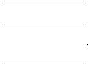
1.3Elmo Documentation
This manual – included in the Elmo CANopen Implementation Guide – is part of the Elmo SimplIQ digital servo drive documentation set, as outlined in the following diagram:
CANopen Implementation Guide
SimplIQ Software Manual
SimplIQ Command Reference Manual
Programming
Composer User Manual
Setup
|
|
|
|
|
|
|
|
|
SimplIQ Servo Drive |
|
|
|
|
|
|
|
|||
Installation |
|
|
|
|
|
|
|
|
Installation Guides |
|
|
|
|
|
|
|
|
||
|
|
|
|
|
|
|
|
||
|
|
|
|
|
|
|
|
|
|
|
|
|
|
|
|
|
|
|
|
|
|
|
|
|
|
|
|
|
|
|
|
|
|
|
|
|
|
|
|
In addition to this document, the SimplIQ documentation set includes:
The Harmonica, Cello and Bassoon Installation Guides, which provides full instructions for installing a drive
The Composer User Manual, which includes explanations of all the software tools that are a part of Elmo’s Composer software environment
The SimplIQ Software Manual, which describes the comprehensive software used with the SimplIQ line of line of line of digital servo drives
This is the main source of detailed explanations of all SimplIQ commands mentioned in this manual.
The SimplIQ Software Manual, which describes the comprehensive software used with the SimplIQ digital servo drive.
The CANopen Implementation Guide, which explains how to implement CANopen DS 301-based communication with a SimplIQ digital servo drive.
SimplIQ drives are fully compliant with CiA’s DSP305 protocol for Layer Setting Service (LSS).

CANopen DSP 402 Implementation Guide |
4 |
|
MAN-CAN402IG (Ver. 1.2) |
||
|
||
|
|
2: The DSP 402 Object Dictionary
This section describes the objects related to the DSP 402 device specific functionality. For more information about the object dictionary, refer to the Elmo SimplIQ CANopen DS 301 Implementation Guide.
Name |
Index |
Description |
Access |
Mappable? |
Abort |
0x6007 |
Function to perform on heartbeat |
R/W |
N |
connection |
|
event. (Link) |
|
|
option code |
|
|
|
|
Error code |
0x603F |
Captures the last error |
R |
N |
Controlword |
0x6040 |
Allows changing of drive states. |
R/W |
Y |
Statusword |
0x6041 |
Indicates current drive status. |
R |
Y |
Quick stop |
0x605A |
Sets the quick stop option code. |
R/W |
N |
option code |
|
|
|
|
Shut down |
0x605B |
Sets the shut down option code. |
R/W |
N |
option code |
|
|
|
|
Disable |
0x605C |
Sets the disable operation option code. |
R/W |
N |
operation option |
|
|
|
|
code |
|
|
|
|
Halt option code |
0x605D |
Sets the Halt option code. |
R/W |
N |
Fault reaction |
0x605E |
Sets drive reaction when fault occurs. |
R/W |
N |
option code |
|
|
|
|
Modes of |
0x6060 |
Sets mode of operation |
R/W |
Y |
operation |
|
|
|
|
Modes of |
0x6061 |
Displays actual mode of operation. |
R |
N |
operation |
|
|
|
|
display |
|
|
|
|
Position |
0x6062 |
Output of profiler. Position |
R |
Y |
demand value |
|
command. |
|
|
Actual position |
0x6063 |
Actual position taken from position |
R |
Y |
internal unit |
|
sensor, in increments. |
|
|
Position actual |
0x6064 |
Actual position as taken from |
R |
Y |
value |
|
position sensor, in user units. |
|
|
Position |
0x6065 |
Defines a range of tolerated position |
R/W |
N |
following error |
|
values symmetrical to the position |
|
|
window |
|
demand value. |
|
|
Position |
0x6066 |
Defines the timeout for the next error |
R/W |
N |
following error |
|
window to set the following error |
|
|
window time |
|
indication. |
|
|
Position |
0x6067 |
Defines a symmetrical position |
R/W |
N |
window |
|
window for the target position for |
|
|
|
|
target reached indication. |
|
|
CANopen DSP 402 Implementation Guide |
5 |
|
MAN-CAN402IG (Ver. 1.2) |
||
|
||
|
|
Name |
Index |
Description |
Access |
Mappable? |
Position |
0x6068 |
Defines the time in which the position |
R/W |
N |
window time |
|
within the position window indicates |
|
|
|
|
target reached. |
|
|
Velocity sensor |
0x6069 |
Actual velocity as calculated from the |
R |
Y |
actual value |
|
main velocity sensor, in increments. |
|
|
Velocity sensor |
0x606A |
Selects the velocity sensor reading |
R/W |
N |
selection code |
|
from either the position or the |
|
|
|
|
velocity sensor. |
|
|
Velocity |
0x606B |
Demand value for velocity controller. |
R |
Y |
demand value |
|
|
|
|
Velocity actual |
0x606C |
Actual velocity from either position |
R |
Y |
sensor |
|
or velocity sensor. |
|
|
Velocity |
0x606D |
Monitors whether required target |
R/W |
N |
window |
|
velocity was achieved. |
|
|
Velocity |
0x606E |
Defines the time in which a target |
R/W |
N |
window time |
|
velocity is considered as reached. |
|
|
Velocity |
0x606F |
Defines the value in which the |
R/W |
N |
threshold |
|
velocity is considered to be 0. |
|
|
Velocity |
0x6070 |
Defines (with object 0x607F) the time |
R/W |
N |
threshold time |
|
in which the velocity is considered to |
|
|
|
|
be 0. |
|
|
Target torque |
0x6071 |
The input value for the torque |
R/W |
Y |
|
|
controller in profile torque mode. |
|
|
Max torque |
0x6072 |
The maximum permissible torque in |
R/W |
N |
|
|
the motor. |
|
|
Max current |
0x6073 |
The maximum permissible torque |
R/W |
N |
|
|
creating current in the motor. |
|
|
Torque demand |
0x6074 |
The maximum permissible torque |
R |
N |
value |
|
creating current in the motor. |
|
|
Motor rated |
0x6075 |
This value is taken from the motor |
R/W |
N |
current |
|
nameplate. |
|
|
Motor rated |
0x6076 |
This value is taken from the motor |
R/W |
N |
torque |
|
name plate. |
|
|
Torque actual |
0x6077 |
The instantaneous torque in the drive |
R |
Y |
value |
|
motor. |
|
|
Current actual |
0x6078 |
The instantaneous current in the |
R |
Y |
value |
|
drive motor. |
|
|
Profiled target |
0x607A |
Defines target position for absolute or |
R/W |
Y |
position |
|
relative point-to-point motion. |
|
|
Position range |
0x607B |
Sets the limits in which the position |
R/W |
N |
limit |
|
numerical values are available. |
|
|

CANopen DSP 402 Implementation Guide |
6 |
|
MAN-CAN402IG (Ver. 1.2) |
||
|
||
|
|
Name |
Index |
Description |
Access |
Mappable? |
Homing offset |
0x607C |
Defines offset from homing zero |
R/W |
N |
|
|
position to application zero position. |
|
|
Software |
0x607D |
Defines limits for demand position |
R/W |
N |
position limit |
|
value and actual position value. |
|
|
Polarity |
0x607E |
Sets polarity for position or speed |
R/W |
Y |
|
|
command and actual value. |
|
|
Max profile |
0x607F |
Defines limit to which a profile |
R/W |
N |
velocity |
|
velocity speed is saturated. |
|
|
Profile velocity |
0x6081 |
Sets the speed for the profile position |
R/W |
Y |
|
|
motion. |
|
|
Profile |
0x6083 |
Defines the acceleration for the |
R/W |
Y |
acceleration |
|
profile velocity and profile position |
|
|
|
|
motion. |
|
|
Profile |
0x6084 |
Defines deceleration for profile |
R/W |
N |
deceleration |
|
velocity and profile position motion. |
|
|
|
|
|
|
|
Quick stop |
0x6085 |
Sets the deceleration for a quick stop |
R/W |
N |
deceleration |
|
state. |
|
|
Motion profile |
0x6086 |
Defines method by which profile |
R/W |
N |
type |
|
motion is evaluated (linear or jerk) |
|
|
Torque slope |
0x6087 |
the rate of change of torque |
R/W |
Y |
Torque profile |
0x6088 |
Used to select the type of torque |
R/W |
N |
type |
|
profile used to perform a torque |
|
|
|
|
change. |
|
|
Position |
0x6089 |
Used to scale position objects. |
R/W |
N |
notation index |
|
|
|
|
Position |
0x608A |
This object defines the position |
R/W |
N |
dimension index |
|
dimension index. |
|
|
Velocity |
0x608B |
This is defined by the physical |
R/W |
N |
notation index |
|
dimensions and calculated by unit type. |
|
|
Velocity |
0x608C |
This is used together with the velocity |
R/W |
N |
dimension index |
|
notation index to define a unit. |
|
|
Acceleration |
0x608D |
The unit is defined by the physical |
R/W |
N |
notation index |
|
dimensions and calculated by unit |
|
|
|
|
type and exponent |
|
|
Acceleration |
0x608E |
This defines the acceleration |
R/W |
N |
dimension index |
|
dimension index, which is used |
|
|
|
|
together with the acceleration |
|
|
|
|
notation index (object 0x608D) to |
|
|
|
|
define a unit |
|
|
|
|
|
|
|

CANopen DSP 402 Implementation Guide |
7 |
|
MAN-CAN402IG (Ver. 1.2) |
||
|
||
|
|
Name |
Index |
Description |
Access |
Mappable? |
Position encoder |
0x608F |
Defines relation between motor |
R/W |
N |
resolution |
|
revolution and position increments. |
|
|
Velocity |
0x6090 |
Defines ratio of encoder increments/ |
R/W |
N |
encoder |
|
sec per motor revolutions/sec. |
|
|
resolution |
|
|
|
|
Position factor |
0x6093 |
Converts position in user units to |
R/W |
N |
|
|
position in internal increments |
|
|
Velocity |
0x6094 |
Converts desired velocity in velocity |
R/W |
N |
Encoder factor |
|
units into internal increments/sec. |
|
|
Velocity factor 1 |
0x6095 |
Converts motor data into velocity |
R/W |
N |
|
|
data. |
|
|
Velocity factor 2 |
0x6096 |
Converts encoder data for position |
R/W |
N |
|
|
into encoder data for velocity. |
|
|
Acceleration |
0x6097 |
Converts the acceleration from user |
R/W |
N |
factor |
|
units to internal increments/sec. |
|
|
Homing method |
0x6098 |
Defines method by which homing |
R/W |
N |
|
|
procedure is performed. |
|
|
Homing speed |
0x6099 |
Sets speed for homing procedure. |
R/W |
N |
Homing |
0x609A |
Sets acceleration for homing |
R/W |
N |
acceleration |
|
sequence. |
|
|
Interpolated |
0x60C0 |
Sets sub-mode for interpolated |
R/W |
N |
position sub |
|
position algorithm. |
|
|
mode |
|
|
|
|
Interpolated |
0x60C1 |
Sets data for interpolation position |
R/W |
Y |
data record |
|
trajectory. |
|
|
Interpolated |
0x60C2 |
Defines time for interpolation |
R/W |
Y |
position time |
|
position trajectory. |
|
|
period |
|
|
|
|
Interpolation |
0x60C4 |
Defines method to store position data |
R/W |
Y: buffer |
data |
|
record. |
|
position |
configuration |
|
|
|
N: all the |
|
|
|
|
|
|
|
|
|
other |
|
|
|
|
entries. |
Position |
0x60FC |
Reads position command in |
R |
Y |
demand value |
|
increments as given to position |
|
|
|
|
controller |
|
|
Digital input |
0x60FD |
Reads digital input according to DSP |
R |
Y |
|
|
402, and also reflects Elmo digital |
|
|
|
|
input logical state. |
|
|
Target velocity |
0x60FF |
Sets velocity reference for velocity |
R/W |
Y |
|
|
profiler. |
|
|

CANopen DSP 402 Implementation Guide |
8 |
|
MAN-CAN402IG (Ver. 1.2) |
||
|
||
|
|
Name |
Index |
Description |
Access |
Mappable? |
Motor type |
0x6402 |
|
R/W |
N |
Motor catalog |
0x6403 |
32 characters. |
R/W |
N |
number |
|
|
|
|
Motor |
0x6404 |
32 characters. |
R/W |
N |
manufacturer |
|
|
|
|
http motor |
0x6405 |
|
R/W |
N |
catalog address |
|
|
|
|
Motor |
0x6406 |
|
R/W |
N |
calibration date |
|
|
|
|
Motor service |
0x6407 |
|
R/W |
N |
period |
|
|
|
|
Driver modes |
0x6502 |
|
R/W |
N |
Drive |
0x6504 |
|
R |
N |
manufacturer |
|
|
|
|
Drive manu- |
0x6505 |
|
R |
N |
facturer web site |
|
|
|
|

CANopen DSP 402 Implementation Guide |
9 |
|
MAN-CAN402IG (Ver. 1.2) |
||
|
||
|
|
3: Emergencies
Emergency messages are detailed in the SimplIQ CANopen Implementation Guide.
4: Predefinition
Object 0x1000: Device type
The object at index 1000h describes the device type and functionality.
The SimplIQ returns 0x20192 for servo drive supporting DSP 402.
Object 0x1001: Error register
All bits are defined as in the SimplIQ CANopen Implementation Manual and CiA DS-301. The device-specific bit in the error register is used by the DSP 402 protocol. The error code can be read from the predefined error field at object 1003h and is compatible with device profiles for drives available for other field bus systems from object 0x603F as well.
The error register captures the latest emergency messages. SimplIQ servo drives allow the user to block the transmission of an emergency according to object 0x2F20. Nevertheless, a blocked emergency message is captured in the relevant entry of the error register.
PDO Mapping
The Elmo drive supports more than one operating mode of DSP 402. It also allows more than one method to set and query commands. In addition, the use of more than one standard PDO is predefined. With the Harmonica, four TPDOs and four RPDOs are free for any mapping according to the Elmo object dictionary. At reset (power up, NMT communication reset and NMT node reset), a default mapping is introduced according to DSP 402. These default mapping can be later changed by the user.
Receive PDO 1 mapped to the controlword in the following manner:
Index |
Sub-index |
Name |
Default Value |
1400h |
0 |
Number of entries |
2 |
|
1 |
COB-ID used by PDO |
4000027Fh |
|
2 |
Transmission type |
255 |
Index |
Sub-index |
Name |
Default Value |
1600h |
0 |
Number of mapped entries |
1 |
|
1 |
Controlword |
6040 00 10h |
CANopen DSP 402 Implementation Guide |
10 |
|
MAN-CAN402IG (Ver. 1.2) |
||
|
||
|
|
Transmit PDO 1 monitors the drive behavior by transmitting the statusword whenever it changes (typically after reception of a controlword):
Index |
Sub-index |
Name |
Default Value |
1800h |
0 |
Number of entries |
3 |
|
1 |
COB-ID used by PDO |
400001FFh |
|
2 |
Transmission type |
255 |
|
3 |
Inhibit Time |
0 |
|
4 |
Reserved |
0 |
|
5 |
Event timer |
0 |
Index |
Sub-index |
|
Name |
Default Value |
1A00h |
1 |
|
Number of entries |
1 |
|
|
|
Statusword |
6041 00 10h |
|
|
|
|
|
Index |
Sub-index |
|
Name |
Default Value |
2F20h |
1 |
|
TPDO1 asynchronous |
0 |
|
|
|
events |
|
|
|
|
|
|
The asynchronous transmission of TPDO1 reflects changes performed 3 milliseconds prior to the transmission.
Receive PDO 2 is mapped to the binary interpreter by default. This is done for compatibility reasons and to enable communication with the Elmo Composer.
Index |
Sub-index |
Name |
Default Value |
1401h |
0 |
Number of entries |
2 |
|
1 |
COB-ID used by PDO |
4000037Fh |
|
2 |
Transmission type |
254 |
Index |
Sub-index |
Name |
Default Value |
1601h |
0 |
Number of entries |
1 |
|
1 |
Binary interpreter |
2013 00 40h |
|
|
command |
|
CANopen DSP 402 Implementation Guide |
11 |
|
MAN-CAN402IG (Ver. 1.2) |
||
|
||
|
|
Transmit PDO 2 is mapped to the binary interpreter result object, transmitted each time the binary interpreter completes its processing. The event behavior is set by object 0x2F20, defined in the SimplIQ CANopen Implementation Manual.
Index |
Sub-index |
Name |
Default Value |
1801h |
0 |
Number of entries |
3 |
|
1 |
COB-ID used by PDO |
400002FFh |
|
2 |
Transmission type |
254 |
|
3 |
Inhibit time |
0 |
|
4 |
Reserved |
0 |
|
5 |
Event timer |
0 |
Index |
|
Sub-index |
Name |
Default Value |
1A01h |
1 |
Number of entries |
1 |
|
|
2 |
Binary interpreter result |
2014 00 40h |
|
|
|
|
|
|
Index |
|
Sub |
Name |
Default Value |
2F20h |
|
2 |
TPDO2 events |
0x8000000 |
|
|
|
|
|
CANopen DSP 402 Implementation Guide |
12 |
|
MAN-CAN402IG (Ver. 1.2) |
||
|
||
|
|
5:Common Entries
5.1Drive Error
The drive functionality in case of an error is determined using the following objects: 6007h: defined according to the SimplIQ CANopen Implementation Manual.
603Fh: reflects the 16 lower bits of object 0x1003, which, together with this object, get the emergency value regardless of the emergency message mask in object 2F21h.
Object 0x6007: Abort connection option code
This object details the motor control behavior after a heartbeat failure. It has no effect if the motor is already off.
Object description:
|
Index |
6007h |
|
Name |
Abort connection option code |
|
Object code |
VAR |
|
Data type |
INTEGER16 |
|
Category |
Optional |
Entry description: |
|
|
|
Access |
Read/Write |
|
PDO mapping |
No |
|
Value range |
-32,768…32,767 |
|
Default value |
0 |
Data description:
(Command details are found in SimplIQ Command Reference Manual.)
Option |
|
|
Code |
Meaning |
Details |
0 |
No action |
|
1 |
Malfunction |
Motor is off (MO=0) and motor failure code is |
|
|
0x800. The failure is reported and possibly |
|
|
activates an AUTOERR routine similar to |
|
|
other failures (MF command). |
2 |
Device control |
Motor is off (MO=0), but no failure indication |
|
command |
is set (MF=0). |
|
“Disable_voltage” |
|
3 |
Device control |
ST command is executed. Its action depends |
|
command “Quick_stop” |
on unit mode (UM). |
CANopen DSP 402 Implementation Guide |
13 |
|
MAN-CAN402IG (Ver. 1.2) |
||
|
||
|
|
Object 0x603F: Error code
This object captures the code of the last error that occurred in the drive. It corresponds to the value of the lower 16 bits of object 1003h, pre-defined error field.
Object description:
|
Index |
|
603Fh |
|
Name |
|
Error code |
|
Object code |
|
VAR |
|
Data type |
|
UNSIGNED16 |
|
Category |
|
Optional |
Entry description: |
|
|
|
|
|
|
|
|
Access |
|
Read only |
|
PDO mapping |
|
No |
|
Value range |
|
UNSIGNED16 |
|
Default value |
|
0 |
5.2Motor Data
Objects 6402h to 64FFh serve as a database for motor parameters. The values are typically found on the motor nameplate or the manufacturer’s motor catalog and are used to maintain a service database within the controlling device of the drive. Most of the entries are typically entities from the manufacturer’s motor catalog. The Elmo DSP 402 implementation supports the following objects:
6402h: Motor type
6403h: Motor catalog number 6404h: Motor manufacturer 6405h: Http motor catalog address 6406h: Motor calibration date 6407h: Motor service period
Object 0x6402: Motor type
This object defines the type of motor driven by the controller. The values of this object are represented in the following table:
Object values:
Value |
Motor Type |
0 |
Non-standard motor |
1 |
DC motor |
9 |
Micro-step stepper motor |
10 |
Sinusoidal PM brushless motor |
11 |
Trapezoidal PM brushless motor |

CANopen DSP 402 Implementation Guide |
14 |
|
MAN-CAN402IG (Ver. 1.2) |
||
|
||
|
|
This object contains information for the user only and does not convey the value of the CA[28] command at the calibration procedure of a drive.
Object description: |
|
Index |
6402h |
Name |
Motor type |
Object code |
VAR |
Data type |
UNSIGNED16 |
Category |
Optional |
Entry description: |
|
Access |
Read/Write |
PDO mapping |
No |
Value range |
UNSIGNED16 |
Default value |
|
Object 0x6403: Motor catalog number
This object describes the manufacturer’s motor catalog number (nameplate number). The maximum length of this object is 32 characters.
Object description:
|
Index |
6403h |
|
Name |
Motor catalog number |
|
Object code |
VAR |
|
Data type |
VISIBLE_STRING |
|
Category |
Optional |
Entry description: |
|
|
|
Access |
Read/Write |
|
PDO mapping |
No |
|
Value range |
|
|
Default value |
|
CANopen DSP 402 Implementation Guide |
15 |
|
MAN-CAN402IG (Ver. 1.2) |
||
|
||
|
|
Object 0x6404: Motor manufacturer
This object gives the motor manufacturer’s name. The maximum length of this object is 32 characters.
Object description:
Index |
6404h |
Name |
Motor manufacturer |
Object code |
VAR |
Data type |
VISIBLE_STRING |
Category |
Optional |
Entry description: |
|
Access |
Read/Write |
PDO mapping |
No |
Value range |
|
Default value |
|
Objects of data type VISIBLE_STRING have 32 characters.
Object 0x6406: Motor calibration data
Date of the motor last inspection.
Object description:
|
Index |
|
6406h |
|
Name |
|
Motor calibration date |
|
Object code |
|
VAR |
|
Data type |
|
TIME_OF_DAY |
|
Category |
|
Optional |
Entry description: |
|
|
|
|
|
|
|
|
Access |
|
Read/Write |
|
PDO mapping |
|
No |
|
Value range |
|
No |
|
Default value |
|
No |

CANopen DSP 402 Implementation Guide |
16 |
|
MAN-CAN402IG (Ver. 1.2) |
||
|
||
|
|
Object 0x6407: Motor service periods
Value, in hours, of the nominal motor lifetime. The motor needs servicing after this time. Object description:
|
Index |
|
6407h |
|
Name |
|
Motor service period |
|
Object code |
|
VAR |
|
Data type |
|
UNSIGNED32 |
|
Category |
|
Optional |
Entry description: |
|
|
|
|
|
|
|
|
Access |
|
Read/Write |
|
PDO mapping |
|
No |
|
Value range |
|
Unsigned32 |
|
Default value |
|
No |
5.3Drive Data
Objects 6500h to 65FFh serve as a database for drive parameters. The Elmo DSP 402 implementation supports the following objects:
6502h: Supported drive modes:
Homing mode (hm), profiled position mode (pp), interpolated position mode (ip), profiled velocity mode (pv), Profiled torque mode (tq).
6504h: Drive manufacturer 6505h: Http drive catalog address 60FDh: Drive digital input
These objects, except 6503h, are “read only” and are burnt into the drive as part of the manufacturing process. Object 6503h is a non-volatile object, which serves as a database for the user to enter the type of drive as appears in the nameplate (for example,
HAR A15/200CAN). The default value is 0.
The following objects provide more information about the drive: 1008h: Manufacturer device name
100Ah: Manufacturer software version

CANopen DSP 402 Implementation Guide |
17 |
|
MAN-CAN402IG (Ver. 1.2) |
||
|
||
|
|
Object 0x6502: Supported drive modes
Object description: |
|
|
|
|
|
|
|
|
|
|
||||||
|
|
|
|
|
|
|
|
|
|
|
|
|
|
|
|
|
|
Index |
|
|
|
|
|
6502h |
|
|
|
|
|
|
|
|
|
|
Name |
|
|
|
|
|
Supported drive modes |
|
|
|
|
|
||||
|
Object code |
|
|
|
VAR |
|
|
|
|
|
|
|
|
|
||
|
Data type |
|
|
|
|
|
UNSIGNED32 |
|
|
|
|
|
|
|
||
|
Category |
|
|
|
|
|
Optional |
|
|
|
|
|
|
|
||
Entry description: |
|
|
|
|
|
|
|
|
|
|
||||||
|
|
|
|
|
|
|
|
|
|
|
|
|
|
|
|
|
|
Access |
|
|
|
|
|
Read only |
|
|
|
|
|
|
|
||
|
PDO mapping |
|
|
|
No |
|
|
|
|
|
|
|
|
|
||
|
Value range |
|
|
|
UNSIGNED32 |
|
|
|
|
|
|
|||||
|
Default value |
|
|
|
0x65 |
|
|
|
|
|
|
|
|
|
||
Data description: |
|
|
|
|
|
|
|
|
|
|
|
|
|
|||
31 |
16 |
|
15 |
7 |
6 |
|
5 |
4 |
3 |
2 |
1 |
0 |
||||
|
Manufacturer |
|
reserved |
ip |
|
hm |
reserved |
|
tq |
pv |
vl |
pp |
||||
|
specific |
|
|
|
|
|
|
|
|
|
|
|
|
|
|
|
Object 0x6504: Drive manufacturer
This object gives the drive manufacturer’s name.
Object description:
|
Index |
6504h |
|
Name |
Drive manufacturer |
|
Object code |
VAR |
|
Data type |
VISIBLE_STRING |
|
Category |
Optional |
Entry description: |
|
|
|
Access |
Read only |
|
PDO mapping |
No |
|
Value range |
|
|
Default value |
Elmo Motion Control Ltd. |
According to DSP 402, object 0x6504 has read/write access, although with the Harmonica, it has read only access.

CANopen DSP 402 Implementation Guide |
18 |
|
MAN-CAN402IG (Ver. 1.2) |
||
|
||
|
|
Object 0x6505: http drive catalog address
This object gives the Internet address of the drive manufacturer.
Object description:
|
Index |
6505h |
|
Name |
http drive catalog address |
|
Object code |
VAR |
|
Data type |
VISIBLE_STRING |
|
Category |
Optional |
Entry description: |
|
|
|
Access |
Read only |
|
PDO mapping |
No |
|
Value range |
|
|
Default value |
http:\\www.elmomc.com |
According to DSP 402, object 0x6505 has read/write access, although with the SimplIQ, it has read only access.
Object 0x60FD: Digital inputs
This object defines simple digital inputs for drives.
The reflected functions are:
•Negative limit switch – Similar to RLS
•Positive limit switch – Similar to FLS
•Home switch – As reflected in the IL[5] command
Object description:
|
Index |
|
60FDh |
|
Name |
|
Digital inputs |
|
Object code |
|
VAR |
|
Data type |
|
UNSIGNED32 |
|
Category |
|
Optional |
Entry description: |
|
|
|
|
|
|
|
|
Access |
|
Read only |
|
PDO mapping |
|
Yes |
|
Value range |
|
UNSIGNED32 |
|
Default value |
|
0 |
CANopen DSP 402 Implementation Guide |
19 |
|
MAN-CAN402IG (Ver. 1.2) |
||
|
||
|
|
Data description:
31 |
22 |
21 |
16 |
15 |
4 |
3 |
2 |
1 |
0 |
Manufactu |
Digital |
|
Reserved |
Interlock |
Home |
Positive |
Negative |
||
rer specific |
input 1…10 |
|
|
|
switch |
limit |
limit switch |
||
|
|
logic state |
|
|
|
|
switch |
|
|
MSB |
|
|
|
|
|
|
|
|
|
The switch must be “active high.”
Notes:
The interlock is always 0.
“Active high” means that the bit is set to high when the switch is logically active.
Bits 16 – 25 reflect the logic active state of the digital inputs, starting from 1. Logic active means that the switch can be active in either high state or low state according to the IL[N] definition. More information can be found in the SimplIQ
Command Reference Manual.
Different SimplIQ drives support a different number of digital inputs. It is advised to use only the relevant bits according to the specific drive.
This object is evaluated every 3 milliseconds.
When mapped as asynchronous, this object is transmitted at every change within the calculation resolution period. Inhibit time can be used to prevent busload or to control the time latency causing the same TPDO to be transmitted due to other asynchronous events.
CANopen DSP 402 Implementation Guide |
20 |
|
MAN-CAN402IG (Ver. 1.2) |
||
|
||
|
|
6:Device Control
6.1Objects
6040h: controlword 6041h: statusword
The Device Control function block controls all functions of the device, categorized as: Device control of the state machine
Operation mode functions
The state of the device is controlled by the controlword, while the status of the device is indicated by the statusword.
The state machine is controlled externally by the controlword and external signals. Write access to the controlword is always allowed. The SimplIQ is always in external mode, thus the “Remote” indication in the statusword is always ‘1’. The state machine is also controlled by internal signals such as faults and modes of operation.
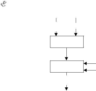
The following diagram illustrates the Device Control function.
The Elmo drive is always in remote mode; that is, it can be controlled only externally by using the SDO and PDO.
controlword Terminals (6040h)
Logical Operation  Remote
Faults
State Machine
Status of the Drive Function
statusword
(6041h)
Figure 6-1: Remote Mode
State Machine
The state machine describes the device status and the possible control sequence of the drive. A single state represents a special internal or external behavior. The state of the drive also determines which commands are accepted; for example, a point-to-point motion can be started only when the drive is in OPERATION ENABLE state.
CANopen DSP 402 Implementation Guide |
21 |
|
MAN-CAN402IG (Ver. 1.2) |
||
|
||
|
|
States may be changed using the controlword and/or according to internal events. The current state can be read using the statusword.
controlword
(6040h)
State Machine |
|
|
Internal Events |
|
|
||
|
|
|
|
statusword
(6041h) Actions
Figure 6-2: State Machine in System Context
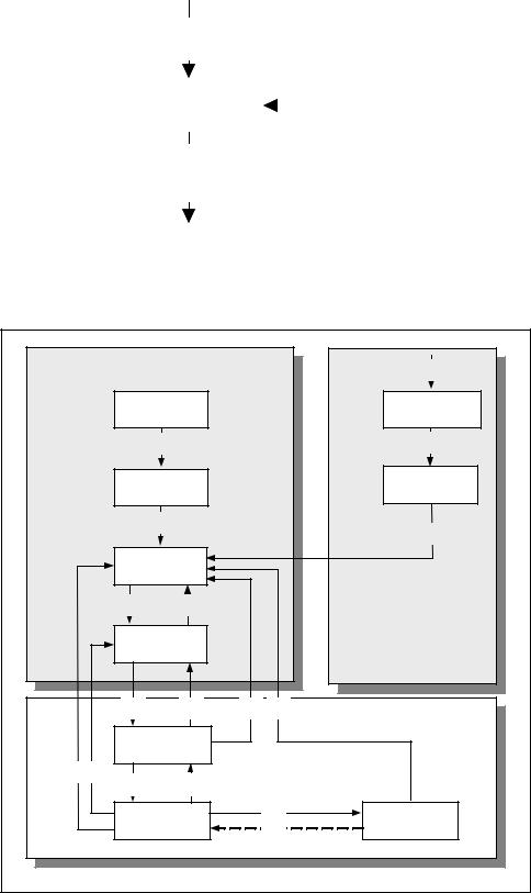
The device states and possible control sequence of the drive are described by the state machine, as depicted in the following figure:
Power |
|
|
|
|
Fault |
13 |
Disabled |
|
|
|
|
|
|
|
Start |
|
|
|
|
FAULT REACTION |
|
|
|
|
|
ACTIVE |
|
|
|
|
|
|
|
|
|
0 |
|
|
|
|
14 |
|
NOT READY TO |
|
|
|
NOT READY TO |
|
|
SWITCH ON |
|
|
|
SWITCH ON |
|
|
1 |
|
|
|
|
15 |
|
|
|
|
|
|
|
|
SWITCH ON |
|
|
|
|
|
|
DISABLED |
|
|
|
|
|
|
2 |
7 |
|
|
|
|
|
READY TO |
|
|
|
|
|
|
SWITCH ON |
|
|
|
|
|
Power |
3 |
6 |
10 |
12 |
|
|
Enabled |
|
|
|
|
|
|
|
SWITCHED ON |
|
|
|
|
|
9 |
8 |
|
|
|
|
|
|
4 |
5 |
|
|
|
|
|
OPERATION |
|
11 |
|
QUICK STOP |
|
|
ENABLE |
|
|
16 |
|
ACTIVE |
Figure 6-3: State Machine Block Diagram

CANopen DSP 402 Implementation Guide |
22 |
|
MAN-CAN402IG (Ver. 1.2) |
||
|
||
|
|
Drive States
The following states of the device are possible:
* NOT READY TO SWITCH ON:
Low-level power (24V) has been applied to the drive. The drive is being initialized and is running the self test. A brake output, if present, is applied in this state.
The drive function is disabled.
This state is an internal state in which communication is enabled only at the end. The user can neither retrieve nor monitor this state.
* SWITCH ON DISABLED:
Drive initialization is complete.
The drive parameters have been set up. Drive parameters may be changed.
High voltage may not be applied to the drive, (such as for safety reasons; refer to following note).
The drive function is disabled.
Notes:
In this state, if high power is applied anyway, no indication of an error is given. The application must be responsible for handling the state transition.
SWITCH ON DISABLED is the minimum state to which a user may switch.
* READY TO SWITCH ON:
High voltage may be applied to the drive. The drive parameters may be changed.
The drive function is disabled.
* SWITCHED ON:
High voltage has been applied to the drive. The power amplifier is ready.
The drive parameters may be changed.
The drive function is disabled.
No indication is given if the drive high voltage has not been applied.
* OPERATION ENABLE:
No faults have been detected.
The drive function is enabled and power is applied to the motor.
The drive parameters may be changed.
(This corresponds to normal operation of the drive.)
In this state, a brake is automatically released according to the brake parameter (BP[N]) timing.

CANopen DSP 402 Implementation Guide |
23 |
|
MAN-CAN402IG (Ver. 1.2) |
||
|
||
|
|
* QUICK STOP ACTIVE:
The drive parameters may be changed. The quick stop function is being executed.
The drive function is enabled and power is applied to the motor.
According to the quick stop option code, the drive stops the motion and either stays in quick stop or disables the motor. The term “drive stops” means that the rfg completed the deceleration trajectory and not that the motor is stationary.
If the quick stop option code (object 0x605A) is 0 (disable drive function), the state of the drive is SWITCH ON DISABLED.
* FAULT REACTION ACTIVE:
The drive parameters may be changed. A fault has occurred in the drive.
The fault reaction function is being executed. The drive function is disabled.
This parameter cannot be retrieved by the user. The drive automatically switches to FAULT state.
* FAULT:
The drive parameters may be changed. A fault has occurred in the drive.
High voltage switch-on/-off depends on the application.
The drive function is disabled.
State Transitions of the Drive Supervisor
State transitions are caused by internal events in the drive or by commands from the host via the controlword.
State Transition 0: START => NOT READY TO SWITCH ON
Event: Reset.
Action: The drive self-tests and/or self-initializes.
State Transition 1: NOT READY TO SWITCH ON => SWITCH ON DISABLED
Event: The drive has self-tested and/or initialized successfully.
Action: Activate communication.
State Transition 2: SWITCH ON DISABLED => READY TO SWITCH ON
Event: Shutdown command received from host.
Action: None
State Transition 3: READY TO SWITCH ON => SWITCHED ON
Event: Switch On command received from host.
Action: The power section is switched on if it is not already on.
CANopen DSP 402 Implementation Guide |
24 |
|
MAN-CAN402IG (Ver. 1.2) |
||
|
||
|
|
State Transition 4: SWITCHED ON => OPERATION ENABLE
Event: Enable Operation command received from host.
Action: The drive function is enabled.
State Transition 5: OPERATION ENABLE => SWITCHED ON
Event: Disable Operation command received from host.
Action: The drive operation is disabled.
State Transition 6: SWITCHED ON => READY TO SWITCH ON
Event: Shutdown command received from host.
Action: The power section is switched off.
State Transition 7: READY TO SWITCH ON => SWITCH ON DISABLED
Event: Quick Stop and Disable Voltage commands received from host.
Action: None.
State Transition 8: OPERATION ENABLE => READY TO SWITCH ON
Event: Shutdown command received from host.
Action: The power section is switched off immediately, and the motor is free to rotate if not braked.
State Transition 9: OPERATION ENABLE => SWITCH ON DISABLED
Event: Disable Voltage command received from host.
Action: The power section is switched off immediately, and the motor is free to rotate if not braked.
State Transition 10: SWITCHED ON =>SWITCH ON DISABLED
Event: Disable Voltage or Quick Stop command received from host.
Action: The power section is switched off immediately, and the motor is free to rotate if not braked.
State Transition 11: OPERATION ENABLE =>QUICK STOP ACTIVE
Event: Quick Stop command received from host.
Action: The quick stop function is executed.
State Transition 12: QUICK STOP ACTIVE=>SWITCH ON DISABLED
Event: Quick Stop completed or Disable Voltage command received from host.
This transition is possible if the quick stop option code is higher than 5 (stay in QUICK STOP ACTIVE state).
Action: The profile generator finished the deceleration and the motor is disabled.
State Transition 13: All => FAULT REACTION ACTIVE
Event: A fault has occurred in the drive.
Action: Execute appropriate fault reaction.
State Transition 14: FAULT REACTION ACTIVE => FAULT
Event: The fault reaction is completed.
Action: The drive function is disabled. The power section may be switched off.
State Transition 15: FAULT=>SWITCH ON DISABLED
Event: Fault Reset command received from host.
Action: The fault condition is reset if no fault currently exists in the drive.
Loading...