


1
Rev 6/95
ISP - Rev 6/95

2
ELMO-WARRANTY PERFORMANCE
The warranty performance covers only ELMO's products and only the elimination of problems that are due to manufacturing defects resulting in impaired function, deficient workmanship or defective material. Specifically excluded from warranty is the elimination of problems which are caused by abuse, damage, neglect, overloading, wrong operation, unauthorized manipulations etc.
The following maximum warranty period applies:
12 months from the time of operational startup but not later than 18 months from
shipment by the manufacturing plant.
Units repaired under warranty have to be treated as an entity.
A breakdown of the repair procedure (for instance of the repair of a unit into repair of cards) is not permissible.
Damage claims, including consequential damages, which exceed the warranty obligation will be rejected in all cases.
If any term or condition in this warranty performance shall be at variance or inconsistent with any provision or condition (whether special or general) contained or referred to in the Terms and Conditions of Sales set out at the back of Elmo's Standard Acknowledge Form, than the later shall prevail and be effective.
ISP - Rev 6/95
3
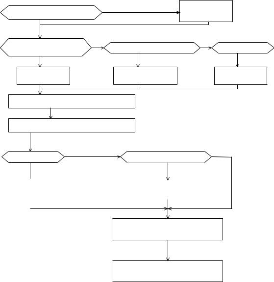
How to use this manual - Flow Chart
The ISP amplifier is designed for OEM applications. It enables the user to adjust the amplifier for various types of motors and to save valuable adjusting time in repetitive applications.
Use the following flow chart in order to determine the chapters that you should read. If you are a new user of the ISP, you should read chapters 1-4 which will familiarize you with the product.
|
no |
Read chapters |
||
Familiar with the ISP ? |
1,2,3,4 |
|
||
|
|
|||
Panel (H) version or Rack (R) |
no |
|
no |
|
Rack (R) with Elmo mother board? |
Elmo enclosure ? |
|||
w/o Elmo mother board ? |
|
|
|
|
Read chapter 5.1 |
Read chapters 5.1+5.2 |
|
|
Read chapter 5.3 |
Terminals |
Terminals |
|
|
Terminals |
Read chapter 6 - Installation |
|
|
|
|
Read chapter 7.1 - Start-Up |
|
|
|
|
no |
Armature voltage feedback ? |
|
no |
|
Brush Tacho ? |
|
|
||
|
|
|
|
|
Read |
|
|
(Current mode) |
|
|
Read |
|||
7.2 |
|
|
7.3 |
|
|
|
|
|
|
|
|
|
|
|
|
|
|
|
|
Read chapter 8 - Adjustments
Read chapter 9 - Summaries
ISP - Rev 6/95
|
|
4 |
|
|
|
TABLE OF CONTENTS |
|
1. |
Description ................................ ........................ |
6 |
|
2. |
Type Designation ................................ ................... |
7 |
|
3. |
Technical specifications ................................ ........... |
7 |
|
4. |
Operation of the servo control ................................ ..... |
8 |
|
|
4.1 |
Inputs................................ ....................... |
8 |
|
4.2 |
Velocity mode................................ ................ |
9 |
|
|
4.2.1 Velocity control using armature voltage feedback ..... |
10 |
|
4.3 |
Current mode................................ ................. |
10 |
|
4.4 |
Current loop................................ ................. |
11 |
|
4.5 |
Current limits................................ ............... |
11 |
|
|
4.5.1 Time dependent peak current limit .................... |
11 |
4.5.2Dynamic contouring of continuous and peak current limits 12
|
4.6 |
Operation of the shunt regulator ............................. |
13 |
|
|
4.7 |
Protective functions ................................ ......... |
14 |
|
|
|
4.7.1 |
Short circuit protection ............................. |
14 |
|
|
4.7.2 |
Under/over voltage protection ........................ |
14 |
|
|
4.7.3 |
Temperature protection ............................... |
14 |
|
|
4.7.4 |
Insufficient load inductance ......................... |
14 |
|
|
4.7.5 Loss of velocity feedback signal ..................... |
14 |
|
|
|
4.7.6 Shunt regulator duty cycle ........................... |
14 |
|
5. |
Terminal Description ................................ ............... |
17 |
||
|
5.1 |
Terminals for Horizontal and Rack mounting versions .......... |
17 |
|
|
5.2 |
Mother Board terminals ................................ ....... |
20 |
|
|
5.3 |
Terminals for ISP mounted in 3U size ENC. .................... |
22 |
|
6. |
Installation procedures ................................ ............ |
26 |
||
|
6.1 |
Mounting................................ ..................... |
26 |
|
|
6.2 |
Wiring |
................................ ....................... |
26 |
|
6.3 |
Load inductance................................ .............. |
27 |
|
|
6.4 |
AC power ................................supply .............. |
27 |
|
|
6.5 |
Wiring ................................diagrams .............. |
28 |
|
7. |
Start - Up Procedures ................................ .............. |
33 |
||
|
7.1 |
Common ...................procedures for all amplifiers types |
33 |
|
|
|
7.1.1 .............................Inhibit and CW/CCW logic |
33 |
|
|
|
7.1.2 ................................ |
Velocity mode ........ |
36 |
|
|
7.1.3 ................................ |
Current mode ......... |
36 |
ISP - Rev 6/95
5
7.1.4Activating the loss of tacho protection (velocity mode only)
................................ ........................... |
37 |
7.1.5 Latch mode of the protective functions .............. |
38 |
7.1.6Activating the dynamic contouring of the current limits 38
7.2 |
Velocity control using tachogenerator feedback .............. |
38 |
7.3 |
Velocity control using armature voltage feedback ............ |
39 |
8. Amplifier adjustment and diagnostics ............................... |
40 |
|
8.1 |
Balance adjustment ................................ .......... |
40 |
8.2 |
Current limit adjustment ................................ .... |
40 |
8.3 |
Adjusting the motor speed (velocity mode only) .............. |
41 |
8.4 |
Adjustment of the IxR compensation .......................... |
41 |
8.5 |
Response adjustment (velocity mode only) .................... |
42 |
9. Tables and Summaries ................................ ............... |
44 |
|
9.1 |
Adjusting trimmers ................................ .......... |
44 |
9.2 |
LED diagnostics ................................ ............. |
44 |
Appendix A - Response adjustment - current loop ........................ |
45 |
|
Appendix B - Current limits contour adjustment ......................... |
47 |
|
List of ELMO Service Centers ................................ ........... |
77 |
|
ISP - Rev 6/95
6
1. Description
The ISP is an amplifier/power supply package, assembled on a single heatsink with a Eurocard size. The rated output is up to 1500W.
The integrated power supply includes a shunt regulator.
The ISP is available in either panel version or rack version with a 32 poles DIN 41612 connector.
Standard features
*Zero deadband.
*Excellent linearity.
*2 inputs.
*Differential input.
*Motor current monitor.
*Inhibit/fault indication (free contact relay).
*Remote control functions: Inhibit and CW/CCW disable.
*Adjustable compensation.
*Adjustable continuous and peak current limits.
*Dynamic contouring of continuous and peak current limits.
*Input balance (offset) adjustment.
*Operation in two velocity modes (Tacho or armature voltage feedback) or current mode.
*LEDs diagnostics.
*Option - Personality board for ease of replacement: the board includes all the adjusting trimmers.
Protective functions:
The following protections cause an inhibit which is either self-restart or latched (for manual reset) selectable by the user:
*Under / over voltage.
*Short circuit: between outputs or each output to ground.
*Low inductance.
*RMS current limit.
*Loss of tacho feedback.
*Over temperature.
*Duty cycle limit of the power supply's shunt regulator.
ISP - Rev 6/95

|
|
|
|
|
|
|
|
|
|
|
|
|
7 |
|
|
|
|
|
|
|
|
|
|
|
||||
2. |
Type Designation |
|
|
|
|
|
|
|
|
|
|
|
|
|
|
|
|
|
|
|
|
|
||||||
|
|
|
|
ISP F - 15 / |
65 R W |
4 |
|
|
|
|||||||||||||||||||
|
|
|
|
|
|
|
|
|
|
|
|
|
|
|
|
|
|
|
|
|
|
|
|
|
|
PWM switching frequency |
||
|
|
ISP amplifier |
|
|
|
|
|
|
|
|
|
|
|
|
|
|
|
|
|
|
|
|
|
|||||
|
|
|
|
|
|
|
|
|
|
|
|
|
|
|
|
|
|
|
|
|
20KHz when not specified |
|||||||
|
|
|
|
|
|
|
|
|
|
|
|
|
|
|
|
|
|
|
|
|
|
|
|
|
||||
|
|
Fan cooled |
|
|
|
|
|
|
|
|
|
|
|
|
|
|
|
|||||||||||
|
|
|
|
|
|
|
|
|
|
|
|
|
|
|
|
|
|
|
|
4=40KHz, 6=60KHz |
||||||||
|
|
Rated current |
|
|
|
|
|
|
|
|
|
|
|
|
|
|
|
|
|
|
|
|
|
|||||
|
|
|
|
|
|
|
|
|
|
|
|
|
|
|
|
|
|
|
|
Additional capacitance |
||||||||
|
|
|
|
|
|
|
|
|
|
|
|
|
|
|
|
|
|
|
|
|
|
|
|
|
|
|||
|
|
|
|
|
|
|
|
|
|
|
|
|
|
|
|
|
|
|
|
|
|
|
||||||
|
|
Maximum rated voltage |
|
|
|
|
|
|
|
|
|
|
|
|
|
for ISP-10/135 only |
||||||||||||
|
|
|
|
|
|
|
|
|
|
|
|
|
|
|
H - Panel mounting |
|||||||||||||
|
|
|
|
|
|
|
|
|
|
|
|
|
|
|
|
|
|
|
|
|
|
|
|
|
|
|||
|
|
|
|
|
|
|
|
|
|
|
|
|
|
|
|
|
|
|
|
|
|
|
|
|
|
R - Rack mounting |
||
3. |
Technical specifications |
|
|
|
|
|
|
|
|
|
|
|
|
|
|
|
|
|||||||||||
|
|
|
|
|
|
|
|
|
|
|
|
|
|
|||||||||||||||
Type |
|
|
AC Supply |
|
Current |
|
Size |
|
|
|
Size |
Weight |
|
|||||||||||||||
|
|
|
** |
|
|
|
|
|
limits |
|
Panel types |
|
|
|
Rack |
|
|
|||||||||||
ISP-8/65 |
14-65 |
|
|
|
|
8/16 |
|
|
|
SP1 |
|
|
|
3U/8T |
0.7 |
|
||||||||||||
ISP-15/65 |
14-65 |
|
|
|
|
15/30 |
|
|
SP1 |
|
|
|
3U/8T |
0.7 |
|
|||||||||||||
ISP-5/135 |
80-135 |
|
|
|
5/10 |
|
|
|
SP1 |
|
|
|
3U/8T |
0.7 |
|
|||||||||||||
ISPF-10/135_W |
28-135 |
|
|
|
10/20 |
|
|
SP3 |
|
|
|
3U/12T |
0.8 |
|
||||||||||||||
ISP-10/135_W |
28-135 |
|
|
|
10/20 |
|
|
SP4 |
|
|
|
3U/19T |
1.6 |
|
||||||||||||||
|
|
|
|
|
|
|
|
|
|
|
|
|
|
|
|
|
|
|
|
|
|
|
|
|
|
|
|
|
*DC output voltage is 130% of AC input voltage.
*20KHz, 40KHz or 60KHz switching frequency.
*2KHz current loop response (minimum)
*Outputs voltages of +5V/100mA, +15V/50mA each, for external use.
*Efficiency at rated current - 97%.
*Drift: 10æV/§C (referred to input)
*Operating temperature: 0-50 §C.
*Storage temperature: -10 - +70 §C.
* The W version includes additional 3000 æF in the bus filter.
** These are the absolute minimum-maximum AC supply voltages under any condition.
ISP - Rev 6/95
8
4. Operation of the servo control
4.1Inputs
The ISP has 3 inputs: 2 single ended inputs (no.1 at terminal 1 and no.2 at
terminal 5) and one differential input at terminals 3,4.
The current gain of inputs 1 and 2 (current mode) is given by:
8 x Ic x Ki |
|
Gc = --------------- |
(A/V) |
15 + Ri |
|
Ic - amplifier rated continuous current.
Ri - input resistor in Kohm.
R1 for input 1
R2 for input 2
Ki - position of wiper of trimming potentiometer
Ki=0.33 when trimmer is fully CW.
Ki=1 when trimmer is fully CW.
The current gain of |
the differential input for R3=R4 (current mode) is given |
by: |
|
|
|
5.33 x Ic |
|
Gcd = ------------- |
(A/V) |
R3 |
|
R3 in Kohm |
|
The current gain of the single ended inputs in velocity mode is given by (place the appropriate Gc for each input):
400 x Ic x Ki |
|
Gv = ----------------- |
(A/V) |
(15+Ri)xR6 |
|
Ri,R6 in Kohm |
|
ISP - Rev 6/95

9
The current |
gain of the differential input in velocity mode is given by: |
|
|
266 |
x Ic |
Gvd = ---------------- |
(A/V) |
R3 |
x R6 |
R3,R6 in Kohm |
|
The maximum input voltage at terminals 1 or 5 is calculated by:
Vinmax = 10 + 0.6Ri (Volts)
Ri in Kohm
The maximum input voltage at terminals 3,4 is calculated by:
Vdmax |
= 10 + R3 |
(Volts), |
R3=R4 |
in Kohm |
|
4.2Velocity mode
In this mode op amp U1/A is employed as a high gain error amplifier The amplifier sums velocity command and the tachogenerator feedback signal, and provides the necessary servo compensation and gain adjustments, resulting in stable, optimum servo operation.
This op amp is configured with two feedback paths:
One, in the form of a resistive T network, controls the DC gain of this amplifier. The equivalent value of a T network is given by:
1010 Rf= --------
R6
Resistor R6 is mounted in solderless terminals so it can be changed easily whenever the DC gain of the error amplifier is to be changed. The AC gain is controlled by C1, R5 and COMP trimmer. Maximum AC gain is obtained with COMP trimmer set fully CW. Setting COMP trimmer fully CCW removes AC gain and no lag in response occurs. R5 and C1 are mounted in solderless terminals and can be
ISP - Rev 6/95

10
easily replaced in cases when COMP trimmer range is not enough to get optimum result.
The output of the error amplifier is:
1 + SxC1xR5
Vo = (V1Gv1 + V2Gv2) x [ --------------------------- ]
1 + SxC1xR5(1 + RfxKi/R5)
V1,V2, - Input signals
Gv1,Gv2 - Gain of inputs.
Ki = Position factor of the wiper of COMP trimmer.
Full CW = 0.1
Full CCW = 1
The feedback element must be connected for negative feedback.
The polarity of the ISP servo amplifiers is such that a positive input signal results in a negative voltage at terminal M1 with respect to terminal M2.
4.2.1Velocity control using armature voltage feedback
By inserting R8 to its solderless terminals, the armature voltage is fed into the error amplifier to be used as a velocity feedback. This feature is useful for all cases when low regulation ratio and low speed accuracy are acceptable.
4.3Current mode
In order to operate the servo amplifier as a current amplifier, the velocity loop should be disabled. This is done by converting the error amplifier into a low gain DC amplifier which has a flat response beyond the desired current bandwidth. In this mode, R6 and C1 have to be removed from the circuit.
ISP - Rev 6/95
11
4.4Current loop
Current loop control is obtained by op amp U1/B (Current amplifier) and R7, C2 which form a lag-lead network for current loop. The standard amp is equipped with R7 (100Kohm) and C2 (0.01æF) to get optimum current response for an average motor in this power range. These components are mounted in solderless terminals.
4.5Current limits
The servo amplifier can operate in the following voltage-current plane:
|
|
+V |
|
-Ip |
-Ic |
Ic |
Ip |
Intermittent |
Continuous |
|
|
zone |
zone |
-V |
|
Ic - Continuous current |
Ip - Peak current |
Fig. 4.1: Voltage-Current plane |
|
Each amplifier is factory calibrated to have this shape of voltage-current operating area with rated values of continuous and peak current limits. In addition the peak current limit is time dependent as explained in 4.5.1.
4.5.1Time dependent peak current limit
The peak current is so designed that its duration is a function of the peak amplitude and the motor actual operating current before the peak demand. The maximum peak current is available for 1.6 second. The duration of Ip is given by:
ISP - Rev 6/95
12
Ip - Iop
Tp = 2.2ln ----------
Ip - Ic
Ic - Amplifier continuous current rating.
Ip - Peak demanded (not amplifier Ip)
Iop - Actual operating current before the peak demand.
Example:
A motor is driven by an ISP-15/65 amplifier at constant speed and constant current of 5A. What is the maximum possible duration of a 20A peak ?
20 - 5
Tp = 2.2ln -------- = 2.42 seconds 20 - 15
4.5.2Dynamic contouring of continuous and peak current limits
Most of the servo motors have reduced continuous current limits at high speeds (Fig. 4.2). This phenomenon is due to commutation limits and iron looses which become significantly high as speed increases and this leads to reduction of the continuous current limit. The ISP amplifiers have the features which enable the user to define the current limit envelope as closely as possible to the motor operating envelope defined by the motor manufacturer.
Velocity
Cont. |
Interm. |
|
|
zone |
|
||
zone |
Torque |
||
|
|||
|
|
Fig. 4.2:
Typical operating envelope of a brush servo motor
ISP - Rev 6/95
13
4.6Operation of the shunt regulator
A shunt regulator is included in the power supply section of the ISP. The shunt regulator is a switching type, wherein dissipative elements (resistors) are switched across the DC bus, whenever the voltage reaches a predetermined level. The function of the shunt regulator is to regulate the voltage of the DC bus during the period of motor deceleration, when there is a net energy outflow from the motor to the amplifier. The amplifier handles this reverse energy just as efficiently as it provides energy to the motor, hence, most of the energy is passed through the amplifier to the power supply, where the returning energy charges the filter capacitors above their normal voltage level, as determined by the AC incoming voltage.
When the capacitors charge-up reaches the predetermined voltage level (Vr), the shunt regulator begins its regulating action. The bus is regulated to this range until regeneration ceases.
On multi-axis systems, it is recommended to parallel the DC bus of all the
ISPs.
SHUNT specifications
|
Type |
Reg. Voltage (Vr) |
Reg. Current (A) |
|
|
ISP-8/65 |
91 |
11 |
|
|
ISP-15/65 |
91 |
22 |
|
|
ISP-5/135 |
191 |
6 |
|
|
ISPF-10/135_W |
191 |
12 |
|
|
ISP-10/135_W |
191 |
12 |
|
ISP - Rev 6/95
14
4.7Protective functions
All the protective functions (excluding 4.7.6) activate internal inhibit. There are two modes of resetting the amplifier after the cause of the inhibit disappears: Self Restart and Latch.
-Self restart: The amplifier is inhibited only for the period that the inhibit cause is present.
-Latch: All failures latch the inhibit and only a reset signal will clear the
latch.
4.7.1Short circuit protection
This protection is realized by sensing current in the DC line. Every current peak above a certain value will inhibit the amplifier for a period of approx. 30mS (if in restart mode).
The amplifier is protected against shorts between outputs and either output to ground.
4.7.2Under/over voltage protection
Whenever the DC bus voltage is under or over the limits indicated in the technical specifications, the amplifiers will be inhibited.
4.7.3Temperature protection
Temperature sensor is mounted on the heatsink. If, for any reason, the temperature exceeds 85§C the amplifier will be inhibited. The amplifier will restart when the temperature drops below 80 §C.
4.7.4Insufficient load inductance
Whenever the load inductance is too small, the current spikes will be very high. In such cases the amplifier will be disabled.
4.7.5Loss of velocity feedback signal
If the amplifier loses the velocity feedback signal it will inhibit itself. In the "Self Restart" mode it will restart after a delay of 6-8 seconds.
4.7.6Shunt regulator duty cycle
Whenever the ratio between "ON" time to "OFF" time of the shunt exceeds 5-10% the shunt will be inhibited.
ISP - Rev 6/95

|
|
|
|
|
|
|
15 |
|
|
|
15 |
CURRENT COMMAND MONITOR. |
|
|
|
|
|
||||
|
|
|
|
|
|
C1 |
|
|
|
|
|
|
|
|
|
R5 |
|
|
|
|
|
|
INPUT 1 |
|
R1 |
|
475K |
.022MF |
|
|
||
|
|
|
|
|
|
|
||||
1 |
|
|
1000PF |
|
|
|
||||
|
|
|
|
|
|
|
||||
|
|
|
T7 |
100K |
|
|
100 |
T4 |
|
|
|
4700PF |
|
|
|
10K |
|
|
|||
|
10K |
|
|
|
|
|
|
|
||
2 |
|
|
|
|
100K |
|
100K |
|
|
|
|
|
|
5.11K |
|
|
|
|
C2 |
TO POWER |
|
|
|
|
|
|
|
|
R7 |
|||
|
|
|
|
|
|
|
R6 |
100K |
.01MF |
STAGE |
|
|
.01MF |
|
|
|
|
||||
|
|
|
|
|
|
100PF |
|
|
||
|
|
|
|
|
|
|
|
|
|
|
|
R3 |
|
10K |
|
- |
|
|
10K |
- |
PWM |
|
|
|
|
+ |
|
|
|
|
||
3 |
|
- |
100K |
|
|
|
+ |
CONVERTER |
||
|
|
|
|
|
|
|||||
4 |
|
|
+ |
|
|
|
|
10K |
|
|
R4 |
|
|
|
|
|
|
|
|||
|
|
|
|
|
|
|
|
|
||
|
|
|
|
|
|
|
|
|
|
|
|
|
|
|
|
T2 |
CURRENT |
T3 |
|
CURRNET |
|
|
.01MF |
10K |
|
|
A |
|||||
|
|
IC |
LIMITS |
IP |
|
FEEDBACK |
||||
|
|
|
|
|
|
|
|
|
||
5 |
INPUT 2 |
|
R2 |
|
|
|
|
|
|
|
|
|
|
|
|
|
|
|
|
|
|
|
.1MF |
T6 |
100K |
|
|
|
|
R8 |
ARMATURE |
|
|
|
|
|
|
|
|
A |
|||
|
|
|
10K |
+V |
|
|
|
|
|
VOLTAGE |
|
|
|
|
4.7M |
|
|
|
|
||
|
|
|
|
|
|
|
|
|
||
|
|
|
5.11K |
T5 |
|
|
|
|
|
|
|
|
|
10K |
offset |
|
|
|
|
|
|
|
|
|
|
|
|
|
|
|
||
|
|
|
|
|
|
|
|
|
|
|
7 |
CURRENT |
|
|
-V |
|
|
|
|
|
|
MONITOR |
|
|
|
|
|
|
|
|
|
|
|
|
|
|
|
|
|
|
|
|
|
|
|
|
|
|
CURRENT |
|
|
|
||
17 |
|
|
|
|
CONTOURS |
|
|
|
||
|
|
|
|
|
|
R9 |
|
|
|
|
|
|
|
|
|
|
|
|
|
|
|
|
RELAY |
|
|
|
|
R10 |
|
|
|
|
18 |
|
|
|
|
|
|
R11 |
|
|
|
|
|
|
|
|
|
R12 |
|
|
|
|
|
|
|
|
|
|
|
|
|
|
|
|
|
|
|
|
|
|
R13 |
|
|
|
16 |
BACK EMF OUTPUT |
|
|
|
|
|
A |
|
||
|
|
|
|
|
|
|
|
|
||
|
CW |
|
|
|
|
|
|
|
|
|
8 |
|
|
R19a |
|
PROTECTIONS |
|
|
|||
|
|
|
|
|
inhibit latch |
|
|
|
||
|
|
|
|
|
|
|
|
|
||
|
CCW |
|
|
|
|
|
D17 |
|
|
|
9 |
|
|
|
|
|
|
|
|
|
|
|
|
|
|
|
loss of tacho |
FROM POWER STAGE |
||||
|
|
|
R20a |
|
|
|||||
|
|
|
|
|
|
R16 |
|
|
|
|
|
|
|
5V |
|
loss of tacho |
|
|
|||
|
INHIBIT |
|
|
5.11K |
|
|
R15 |
|
|
|
|
INPUT |
|
|
|
loss of tacho |
|
|
|||
|
100 |
|
|
|
|
|||||
10 |
|
+ |
|
|
R14 |
|
|
|
||
|
|
|
|
|
|
|
|
|||
|
|
|
|
- |
|
|
|
|
|
|
|
R18 |
|
|
|
|
|
|
|
|
|
|
|
|
2.8V |
|
|
|
|
|
|
|
|
|
+5V |
-15V |
+15V |
|
|
|
|
|
|
|
|
|
|
|
|
|
RESET |
|
|
|
|
11 |
12 |
|
13 |
14 |
|
6 |
|
|
|
ISP - Rev 6/95
16
|
T2 |
T3 |
T4 |
T5 |
T6 |
T7 |
|
|
|
|
IC |
IP |
COMP OFFSET GAIN 2 GAIN 1 |
|
|
|
|||
|
|
|
|
|
|
VS INH IC SO |
|||
|
|
|
|
|
|
L1 |
L2 |
L3 |
L4 |
|
|
|
|
|
|
|
|
|
14 J1 |
U1 |
U5 |
|
|
R1 |
|
U12 |
|
|
13 |
|
|
|
|
|
12 |
||||
|
|
|
|
R2 |
|
|
|
|
11 |
|
|
|
|
R3 |
|
|
|
|
10 |
|
|
|
|
R4 |
|
|
|
|
9 |
U2 |
|
|
|
R5 |
|
|
|
|
8 |
U6 |
|
|
R6 |
|
U14 |
|
|
7 |
|
|
|
|
|
|
|
||||
|
|
|
|
R7 |
|
|
|
|
6 |
|
|
|
|
R8 |
|
|
|
|
5 |
U3 |
|
|
|
R9 |
|
|
|
|
4 |
U7 |
|
|
R10 |
|
|
|
3 |
||
|
|
|
R11 |
|
|
|
2 |
||
|
|
|
|
R12 |
U15 |
|
|
1 |
|
|
|
|
|
R13 |
|
|
U17 |
||
|
|
|
|
|
|
|
|||
|
U8 |
|
|
R14 |
|
|
|
|
|
U4 |
|
|
R15 |
|
|
|
|
||
|
|
|
R16 |
|
|
|
|
||
|
U9 |
|
|
D17 |
|
|
|
|
|
|
|
|
R18 |
|
|
|
|
||
|
|
|
|
C1 |
|
|
|
|
|
|
|
|
|
C2 |
|
|
|
|
|
U13 |
U10 |
|
|
U11 |
|
U16 |
|
|
U18 |
|
|
|
|
|
|
||||
|
|
|
|
|
|
|
|
|
|
|
J3 |
|
|
14 |
|
|
13 |
|
|
12 |
|
U19 |
11 |
|
10 |
||
|
9 |
|
|
8 |
|
|
7 |
|
R19A |
6 |
|
5 |
||
R20A |
4 |
|
3 |
||
|
||
|
2 |
|
|
1 |
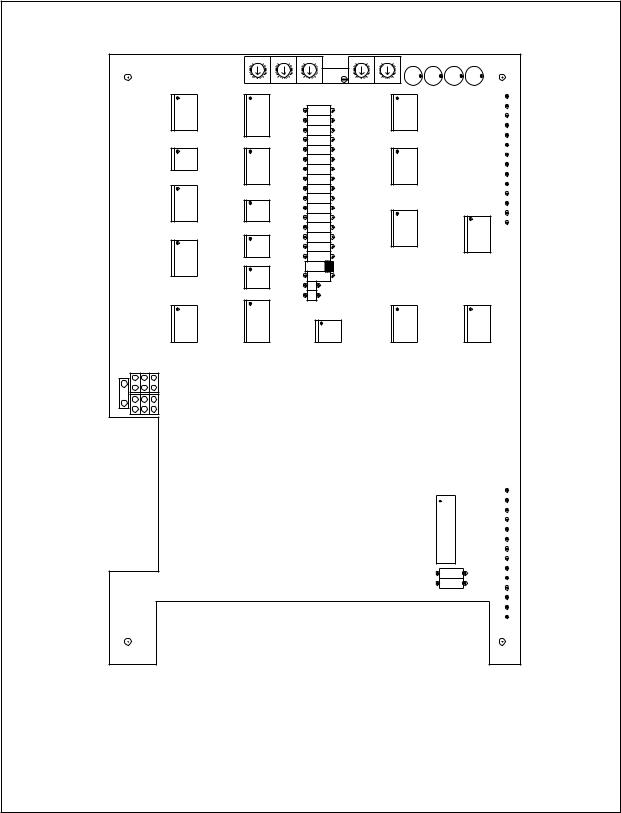
ISP - CONTROL BOARD
ISP - Rev 6/95

17
5. Terminal Description
5.1Terminals for Horizontal and Rack mounting versions
Power stage
H |
R |
|
Function |
Remark |
|
|||
|
|
|
|
|
|
|
|
|
AC |
2ac,4c |
|
AC input |
All pins are shorted on the PCB. |
||||
M1 |
8ac,10a |
|
Armature |
This output will be negative when a positive signal |
||||
|
|
|
|
|
output |
is fed to one of the inputs. All pins are shorted on |
||
|
|
|
|
|
|
the PCB. |
|
|
M2 |
6ac,4a |
|
Armature |
This output will be positive when a positive signal |
||||
|
|
|
|
|
output |
is fed to one of the inputs. All pins are shorted on |
||
|
|
|
|
|
|
the PCB. |
|
|
AC |
12ac,10c |
|
AC input |
All pins are shorted on the PCB. |
||||
|
|
|
|
|
|
|
|
|
Control stage |
|
|
|
|
|
|||
H |
R |
|
Function |
|
Remark |
|
||
|
|
|
|
|
|
|||
1 |
32a |
|
Input 1 |
|
For more details see 4.1. |
|||
2 |
32c |
|
Circuit common |
|
|
|
||
3 |
30a |
|
Negative |
|
For more details see 4.1. |
|||
|
|
|
|
differential |
|
|
|
|
|
|
|
|
input |
|
|
|
|
4 |
30c |
|
Positive |
|
For more details see 4.1. |
|||
|
|
|
|
differential |
|
|
|
|
|
|
|
|
input |
|
|
|
|
5 |
28a |
|
Input 2 |
|
For more details see 4.1. |
|||
6 |
28c |
|
Reset for latch |
low level input |
voltage ** enables the amplifier |
|||
|
|
|
|
mode |
|
(see 7.1.5). |
|
|
7 |
26a |
|
Current monitor |
|
Ic |
|
||
|
|
|
|
|
|
|
Scale is = ------ |
(A/V) |
|
|
|
|
|
|
|
3.75 |
|
8 |
26c |
|
CW disable |
|
Two modes - see chapter 7.1.1 ** |
|||
** -1V < Vil < 1V ; 2V < Vih < 30V Source sink capability - 2mA.
ISP - Rev 6/95

|
|
|
|
|
18 |
|
Control stage - Cont. |
|
|
|
|||
H |
R |
Function |
|
Remark |
|
|
|
|
|
|
|||
9 |
24a |
CCW disable |
Two modes - see chapter 7.1.1 ** |
|||
10 |
24c |
Inhibit input |
Two modes - see chapter 7.1.1 * |
|||
11 |
22a |
Circuit common |
|
|
||
12 |
22c |
+5V |
|
|
100mA |
|
13 |
20a |
-15V |
|
+ 5%, 50mA external load. |
||
14 |
20c |
+15V |
|
+ 5%, 50mA external load. |
||
15 |
18a |
Current |
command |
Ic |
|
|
|
|
monitor |
|
Scale is = ------ |
(A/V) |
|
|
|
|
|
|
3.75 |
|
16 |
18c |
Back EMF output |
See Appendix B. |
|
||
17, |
16a, |
Inhibit output |
A potential free relay contact. Closed when |
|||
18 |
16c |
|
|
|
amplifier is enabled. |
|
|
|
|
|
|
Contact rating: 0.5A, 200V, 10W |
|
19 |
14a |
DC |
power |
voltage |
5A max. |
|
|
|
output - common |
|
|
||
20 |
14c |
DC |
power |
voltage |
5A max. |
|
|
|
output - positive |
|
|
||
|
|
|
|
|
|
|
Remark: In the following paragraphs the terminals will be related to all the mounting types as in the the following example:
H-18,R-16c,E-J1/8.
** -1V < Vil < 1V ; 2V < Vih < 30V Source sink capability - 2mA.
ISP - Rev 6/95
|
19 |
20 |
1 |
AC M2 M1 AC |
|
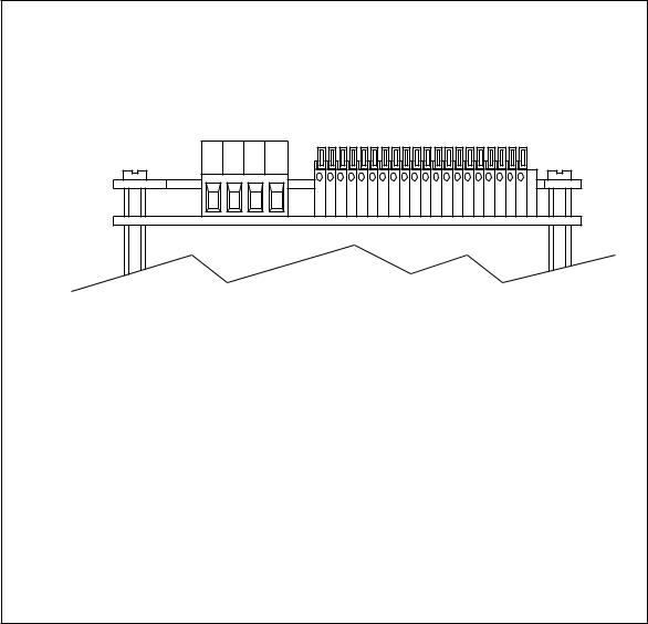
TERMINALS OF ISP - PANEL VERSION |
|
ISP - Rev 6/95
20
5.2Mother Board terminals
The MBA-ISP/N is designed for 19" rack systems. It has screw type terminals for both power and signals with identical designations as in the panel versions except for the following new terminals:
21Potential free Inhibit Input (+). See 7.1.1.
22Potential free Inhibit Input (-). See 7.1.1.
The Potential Free Inhibit Input is applicable only when the "inverted inhibit logic" is used (R18 in the amplifier is inserted). An opto-Coupler (IL5) is used to isolate between the Inhibit signal and the amplifier circuit. Activating this opto-coupler is done by inserting R1 on the mother board according to the following relation:
R1 = 100 x Vinh (ohm)
Vinh - voltage in the inhibit input.
Standard value is 2.4K (For 24 volts) Source must be capable of source or sink 10mA.
ISP - Rev 6/95
21
R1 |
|
|
1 |
|
|
2 |
|
|
3 |
U1 |
|
4 |
||
5 |
|
|
6 |
|
|
7 |
G |
|
8 |
||
9 |
G |
|
10 |
VS |
|
11 |
||
VS |
||
12 |
||
13 |
AC2 |
|
14 |
AC2 |
|
15 |
||
M1 |
||
16 |
||
17 |
M2 |
|
18 |
AC1 |
|
21 |
||
AC1 |
||
22 |
MBA-ISP/N
ISP - Rev 6/95

22
5.3Terminals for ISP mounted in 3U size ENC.
The MBA-ISP/3UE is designed for Elmo enclosures. It has screw type terminals for the power and D-type connectors for the signals.
The Potential Free Inhibit Input is applicable only when the "inverted inhibit logic" is used (R18 in the amplifier is inserted). An opto-Coupler (IL5) is used to isolate between the Inhibit signal and the amplifier circuit. Activating this opto-coupler is done by inserting R1 on the mother board according to the following relation:
R1 = 100 x Vinh (ohm)
Vinh - voltage in the inhibit input.
Standard value is 2.4K (For 24 volts) Source must be capable of source or sink 10mA.
Power Terminals
Terminal |
Function |
Remark |
|
|
|
AC |
AC input |
|
M1 |
Armature |
This output will be negative when a positive signal |
|
output |
is fed to one of the inputs. |
M2 |
Armature |
This output will be positive when a positive signal |
|
output |
is fed to one of the inputs. |
AC |
AC input |
|
GND |
Ground |
|
|
|
|
ISP - Rev 6/95
|
|
|
23 |
|
Control connector - J1 |
|
|
||
Pin |
Function |
|
Remark |
|
|
|
|
|
|
1 |
Input 2 |
|
For more details see 4.1. |
|
2 |
Back EMF output |
See Appendix B. |
|
|
3 |
Input 1 |
|
For more details see 4.1. |
|
4 |
Negative |
|
For more details see 4.1. |
|
|
differential |
|
|
|
|
input |
|
|
|
5 |
Positive |
|
For more details see 4.1. |
|
|
differential |
|
|
|
|
input |
|
|
|
6 |
Current monitor |
Ic |
|
|
|
|
|
Scale is = ------ |
(A/V) |
|
|
|
3.75 |
|
7 |
Current |
command |
Ic |
|
|
monitor |
|
Scale is = ------ |
(A/V) |
|
|
|
3.75 |
|
8,15 |
Inhibit output |
A potential free relay contact. Closed when |
||
|
|
|
amplifier is enabled. |
|
|
|
|
Contact rating: 0.5A, 200V, 10W |
|
9,10 |
Circuit common |
|
|
|
11 |
+15V |
|
+ 5%, 50mA external load. |
|
12 |
-15V |
|
+ 5%, 50mA external load. |
|
13 |
+5V |
|
100mA |
|
14 |
Circuit common |
|
|
|
|
|
|
|
|
ISP - Rev 6/95

|
|
24 |
Control connector - J2 |
|
|
Pin |
Function |
Remark |
1 |
Inhibit input |
Potential free inhibit input (-). |
|
|
See 7.1.1 * |
2 |
Inhibit input |
Potential free inhibit input (+). |
|
|
See 7.1.1 * |
3 |
Inhibit input |
Two modes - see chapter 7.1.1 * |
4 |
CCW disable |
Two modes - see chapter 7.1.1 * |
5 |
CW disable |
Two modes - see chapter 7.1.1 * |
6 |
Reset for latch |
low level input voltage ** enables the amplifier |
|
mode |
(see 7.1.5). |
7 |
Back EMF output |
See Appendix B. |
8 |
Input 2 |
For more details see 4.1. |
9 |
-15V |
+ 5%, 50mA external load. |
10 |
+15V |
+ 5%, 50mA external load. |
11,12 |
Circuit common |
|
13 |
+5V |
100mA |
14,15 |
Circuit common |
|
|
|
|
Remark: In the following paragraphs the terminals will be related to all the mounting types as in the the following example:
H-18,R-16c,E-J1/8.
** -1V < Vil < 1V ; 2V < Vih < 30V Source sink capability - 2mA.
ISP - Rev 6/95
 Loading...