

Page 1

1302 WEST BEARDSLEY AVE • ELKHART, IN 46514 • 1-574-295-8330 • 1-800-346-0250 98291000 REV J
© 2014 ELKHART BRASS MFG. CO., INC. • WWW.ELKHARTBRASS.COM
8294-06, 8294-06 EXT, & 8394-07 Monitors
Installation, Operating, & Maintenance Instructions
Page 2

2
TABLE OF CONTENTS
PRODUCT SAFETY INFORMATION 3
MONITOR CALLOUT DRAWING 4
SYSTEM COMPONENTS 5
INSTALLATION INSTRUCTIONS 9
Installation Step 1: Mount and Wire all System Components 9
Installation Step 2: Communication Address Setup 12
Installation Step 3: RF Settings Setup 13
Installation Step 4: System Programming 15
OPERATING INSTRUCTIONS 18
MAINTENANCE INSTRUCTIONS 21
SYSTEM SPECIFICATIONS 24
MONITOR AND NOZZLE HYDRAULIC DATA 25
COMPONENT MOUNTING TEMPLATES 27
To view the most current parts list and drawings please visit www.elkhartbrass.com
Page 3
3
PRODUCT SAFETY INFORMATION
Important: Before installing and operating provided equipment, read this manual
thoroughly. Proper installation is essential to safe operation.
All personnel who may be expected to use this equipment must be thoroughly trained in its safe and
proper use.
Before flowing water from this device, check that all personnel (fire service and civilian) are out of
the stream path. Also, check to make sure stream direction will not cause avoidable property
damage.
Become thoroughly familiar with the hydraulic characteristics of this equipment, and the pumping
system used to supply it. To produce effective fire streams, operating personnel must be properly
trained.
Whenever possible, this equipment should be operated from a remote location. Do not needlessly
expose personnel to dangerous fire conditions.
Open water valves supplying this equipment slowly so that piping fills slowly, thus preventing
possible water hammer occurrence.
After each use, and on a scheduled basis, inspect equipment per instructions in the Maintenance
section.
Any modifications to the electrical enclosures will destroy the NEMA 4 rating and void warranty
coverage of the enclosure and all components within.
SYSTEM INFORMATION:
MONITOR SERIAL NUMBER:________________________________________________________
MONITOR ACCESSORIES (NOZZLE GALLONAGE AND TYPE, TYPES OF TRANSMITTERS, WATER
VALVE, ETC.):
__________________________________________________________________________________________
__________________________________________________________________________________________
__________________________________________________________________________________________
__________________________________________________________________________________________
__________________________________________________________________________________________
__________________________________________________________________________________________
__________________________________________________________________________________
Page 4

4
MONITOR CALLOUT DRAWING
Optional SM-2000E
Electronically Actuated Nozzle
Fully Vaned Cast
Aluminum or Brass
Waterway
Manual Override
Sealed High-
Torque Gearmotor
8294-06 Scorpion RF Monitor
284A Stream Shaper
3.5” NHT Discharge
Pressure Gauge
RF Receiver/Control Module
4” 150# ANSI Flange
Page 5
5
SYSTEM COMPONENTS
MONITOR
Waterway/Monitor Position
Up-Down Travel Range
Master Stream
+30° to -135°
Egress
+0° to -135°
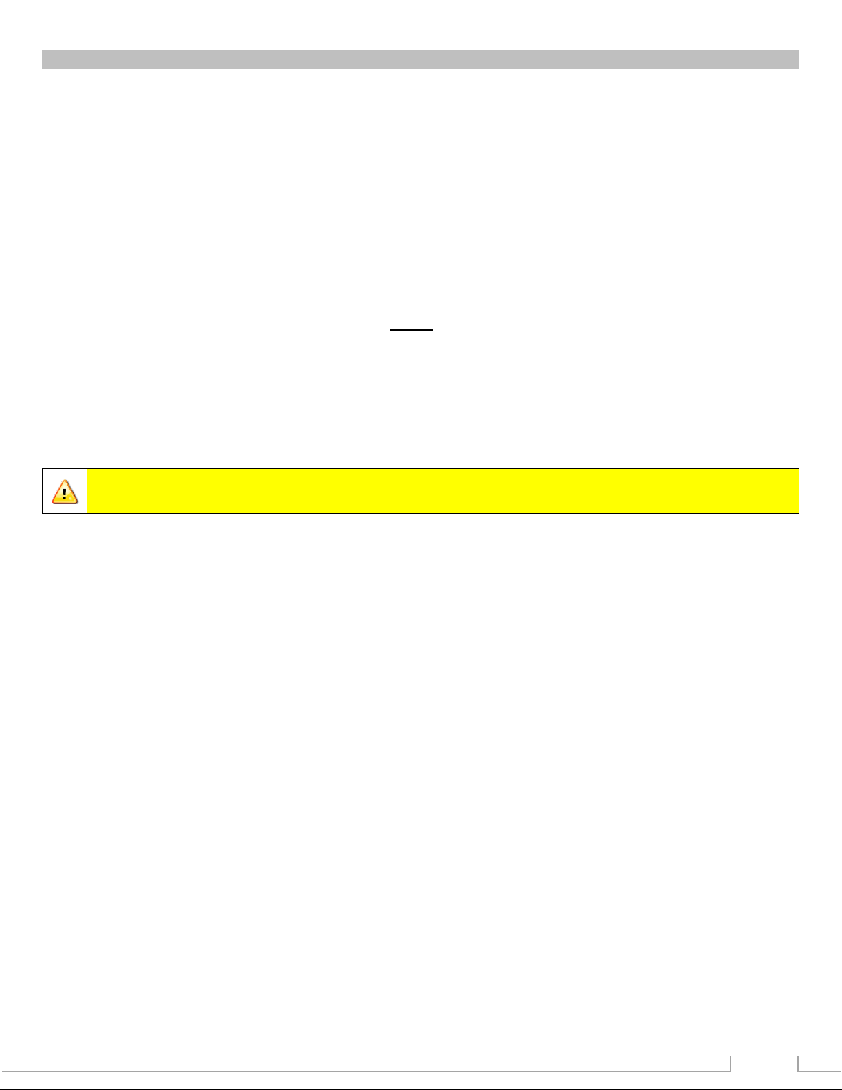
Scorpion RF Monitors – 8294-06 & 8394-07
The 8294-06 and 8294-06 EXT is a cast aluminum monitor with 4”
waterway while the 8394-07 is cast brass. The waterway contains a
central vane to minimize large-scale turbulence and provide superior
fire streams. Monitor water supply connection is a 4 inch 150 lb. ANSI
pattern flange. The discharge nozzle connection is 3½” National Hose
thread. Nozzle stream direction is controlled by two permanent magnet
type planetary gear motors, one controlling rotation about the axis of
the water inlet, and the other controlling nozzle elevation and
depression. Right angle gear cases between the gear motor and the
monitor allow for convenient manual override of the electric motors in
the event of a power failure during firefighting operations. All gearing
is enclosed within the monitor housings.
Scorpion RF Monitor – 8294-06 EXT
The extended travel Scorpion has the same highly efficient waterway
and flow capacity as the Scorpion RF monitor. The monitor waterway is
supplied through a 4” 150# flat faced flange base. The 8294-06 EXT
monitor has a mechanical stop to allow 180° for added protection in an
aerial application.
The extended travel Scorpion RF has special features to
optimize performance as an aerial master stream
device when used on a straight aerial ladder with
pinnable waterway. The pinnable waterway feature
allows the waterway to be pinned to the second fly
section of the ladder (egress position), thus keeping the
monitor and nozzle away from the end fly section when
it is necessary to place the ladder tip at a window sill or
roof parapet.
The 8294-06 EXT contains a special wiring harness connection at the inlet flange to allow attachment
of an OEM provided proximity sensor. The proximity sensor is used to tell the monitor controller which
positions the waterway and monitor is. As a result, the monitor discharge Up-Down travel range differs
for the two waterway and monitor positions as indicated in Table 1.
The 0° position is when the nozzle is aimed parallel to the ladder.
As a further enhancement, the left-right motor direction of rotation automatically reverses when the
monitor discharge is in the range of 0° to +30°. Without this feature, when the discharge travels
above 0°, “left” would functionally become “right” and vice versa.
Table 1: EXT Travel Ranges
Page 6
6
Caution: All monitor motors are 12VDC. If using a non-Elkhart nozzle, another 12VDC
nozzle should be used, or nozzle control may not function properly.
NOZZLE
CONTROL
SM-1250E (P/N: 03781211) &
SM-2000E (P/N: 03990201)
If the proximity sensor changes state while the monitor is in the “master stream” position and the
monitor discharge is in the 0° to 30° “up” range, the monitor controller will automatically lower the
discharge to 0° to prevent possible interference with the ladder, or impingement of stream upon
personnel.
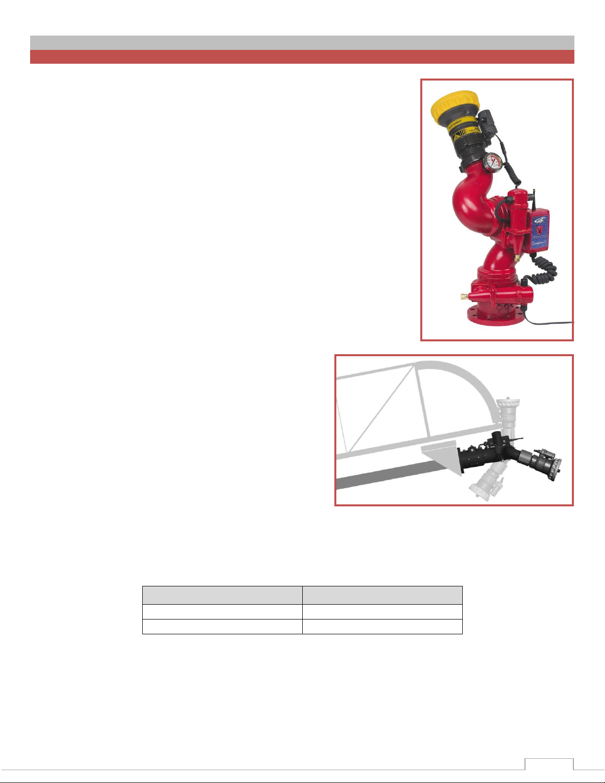
Scorpion RF Nozzles –
There are two nozzles available for the Scorpion RF.
SM-1250E & SM-2000E
The maximum monitor flow capacity is 2000 gallons per
minute. Monitors can be supplied with the SM-1250E (SM1250BE for model 8394-07) constant pressure (automatic)
type master stream nozzle. This nozzle has a flow range of
300 to 1250 gallons per minute at 75 psi and has an electric
drive mechanism for RF control of the spray pattern from a
straight stream to wide fog.
A similar nozzle, the SM-2000E (SM-2000BE for 8394-07), provides a flow range of 500 to 2000
gallons per minute at 80 psi. For optimum straight stream performance, stream shapers are provided
as part of the monitor and nozzle system. Solid stream nozzles are also available for use with these
monitors.
SM-1250E; 350 GPM @ 50 PSI – 1250 GPM @ 75 PSI
SM-2000E; 500 GPM @ 50 PSI – 2000 GPM @ 80 PSI
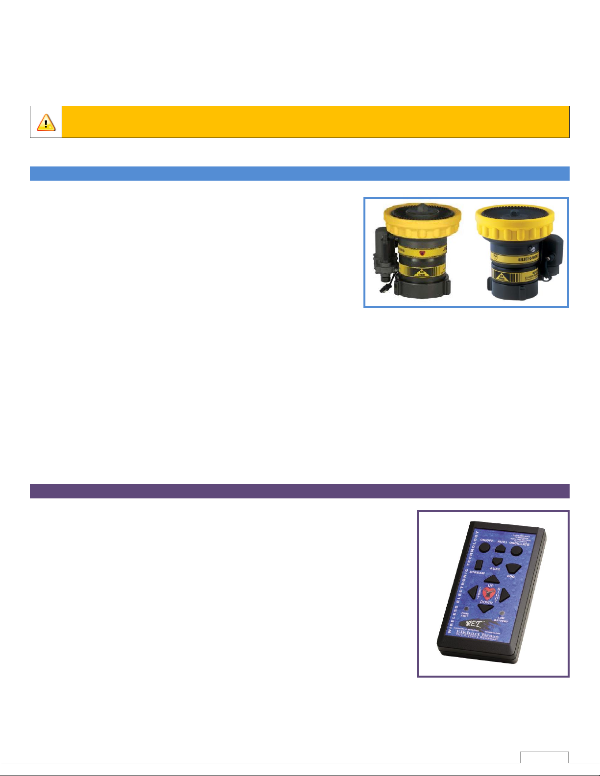
Handheld RF Controller – 81282001
A sealed handheld RF transmitter contains all the controls necessary for
operation of the monitor. The handheld remote allows the operator to
direct the monitor from a significantly improved point of view. With the
wireless remote, the operator can view the stream from the side and
confirm that the stream is hitting its target. Separate push button
switches are provided for up, down, left, right, fog, and stream
functions. The handheld remote has user selectable frequency and
security codes that allow multiple monitors to operate on the same fire
ground at the same time. The remote has an automatic power down
feature that will shut down the power after 5 minutes of no activity. As
an additional power saving feature the radio signal is only transmitted
while a button is pushed. The handheld remote case has a NEMA 4
rating.
Page 7
7
Caution: Any modification of the Handheld Controller or Panel Mount enclosures will
destroy the NEMA 4 rating to that piece of equipment and will void the warranty
coverage.
MONITOR ACCESSORY
Primary Panel Mount RF Controller – 81327101
The fixed RF transmitter sends signals to the monitor via an encoded
radio signal, requiring no wires between the RF transmitter and the
monitor. It is powered by the vehicle electrical system. The faceplate is
intended for a flush mount onto the pump or aerial ladder control
panel. Separate sealed push button switches are provided for up,
down, left, right, fog, and stream functions. This fixed RF transmitter
provides two-button access to the Stow feature. It will override any lowpriority controls, allowing the apparatus operator to retain ultimate
control over the monitor. Comes with 10 foot coax antenna cable and
(1) 90° antenna and (1) straight antenna.
Secondary Panel Mount RF Controller – 81327201
The fixed RF transmitter sends signals to the monitor via an encoded
radio signal, requiring no wires between the RF transmitter and the
monitor. It is powered by the vehicle electrical system. The faceplate is
intended for a flush mount onto the pump or aerial ladder control
panel. Separate sealed push button switches are provided for up,
down, left, right, fog, and stream functions. Comes with 10 foot coax
antenna cable and (1) 90° antenna and (1) straight antenna.
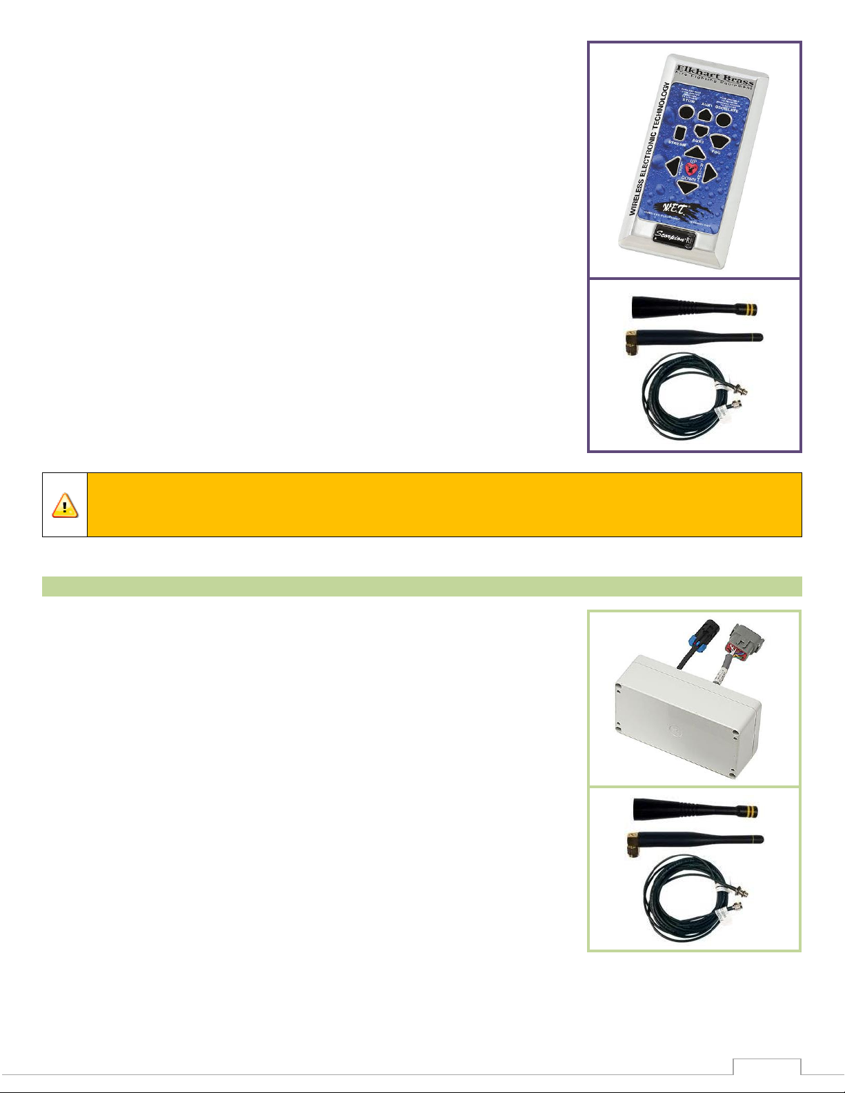
Primary OEM RF Transmitter – 81353101
The OEM RF transmitter allows the monitor installer to use their
switching arrangement while still having the benefit of the W.E.T. It has
all of the same features of the Primary Panel Mount RF controller, but
has a wiring harness for the installer to connect to the switches. Comes
with 10 foot coax antenna cable and (1) 90° antenna and (1) straight
antenna.
Secondary OEM RF Transmitter – 81353201
The OEM RF transmitter allows the monitor installer to use their
switching arrangement while still having the benefit of the W.E.T. It has
all of the same features of the Secondary Panel Mount RF controller, but
has a wiring harness for the installer to connect to the switches. Comes
with 10 foot coax antenna cable and (1) 90° antenna and (1) straight
antenna.
Page 8
8
Caution: Any modification of the enclosures of any of the transmitters or switch box
will destroy the NEMA 4 rating, and will void the warranty coverage. Ensure all O-ring
and gaskets are properly installed when closing receiver or controller enclosures.
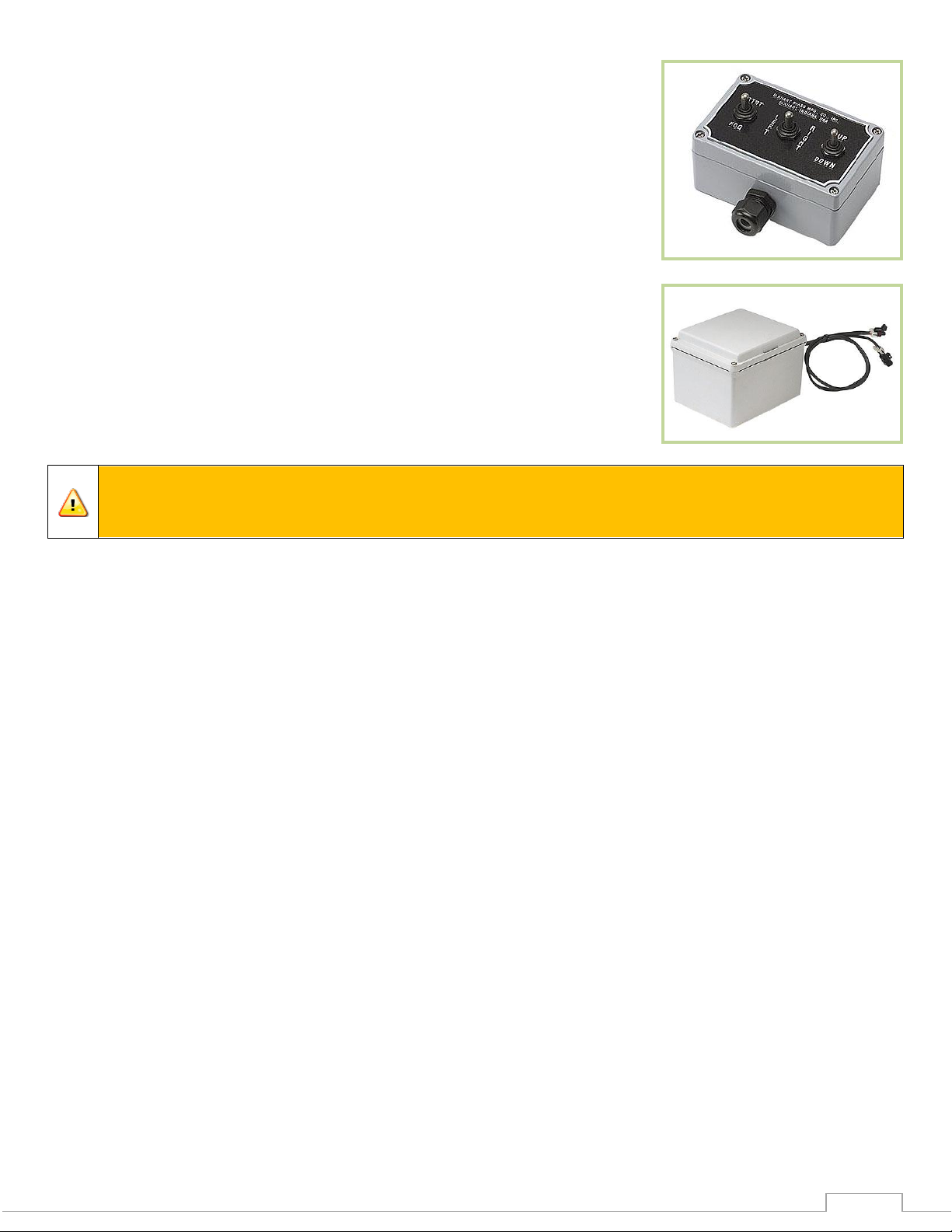
Secondary Switch Box Control for Aerial Application – 81549001
This component is a surface mount type switch box with controls for
operation of the monitor for use with the OEM secondary RF transmitter.
Separate sealed toggle switches are furnished for up-down, left-right,
and strt-fog functions. The box has a NEMA 4 rating, and is generally
installed at the tip of the aerial ladder, or in the bucket of the aerial
platform. A terminal strip inside the enclosure allows for connection of
the control cable, and a watertight strain relief fitting provides for
sealing around the cable entry
Auxilary Battery Pack – 81492001
A 12-volt, 12 amp-hr. sealed lead-acid battery pack is available to
allow operation of the monitor in case of vehicle electrical system
failure. These battery packs are also used as a means to minimize the
required size of conductors routed up aerial ladders and towers. This is
accomplished by mounting the battery pack near the monitor, with a
small trickle-charge conductor to the battery from the vehicle system
DC to DC Converter Function – 24272000
An optional 24 to 12VDC converter board can be added to the RF receiver control module to allow 24
VDC power to the monitor. The converter will supply enough 12VDC power to the monitor to run all
motors simultaneously. It is reverse voltage protected and meets SAE J1113-11 (Immunity to
Conducted Transients on Power Leads) requirements.
Page 9
9
INSTALLATION INSTRUCTIONS
Installation Step 1: Mount and Wire All System Components
Warning: It is up to the system designer to appropriately handle the open circuit
condition of the stow signal. In the open circuit mode there is no source to turn off the
stow signal load, which may lead to erroneous signal indications if not handled properly.
The stow signal is capable of sinking 250mA maximum. Exceeding this value may blow
the internal fuse and the stow output will no longer be able to provide a ground.
Important: Most test lights draw in excess of 1A.
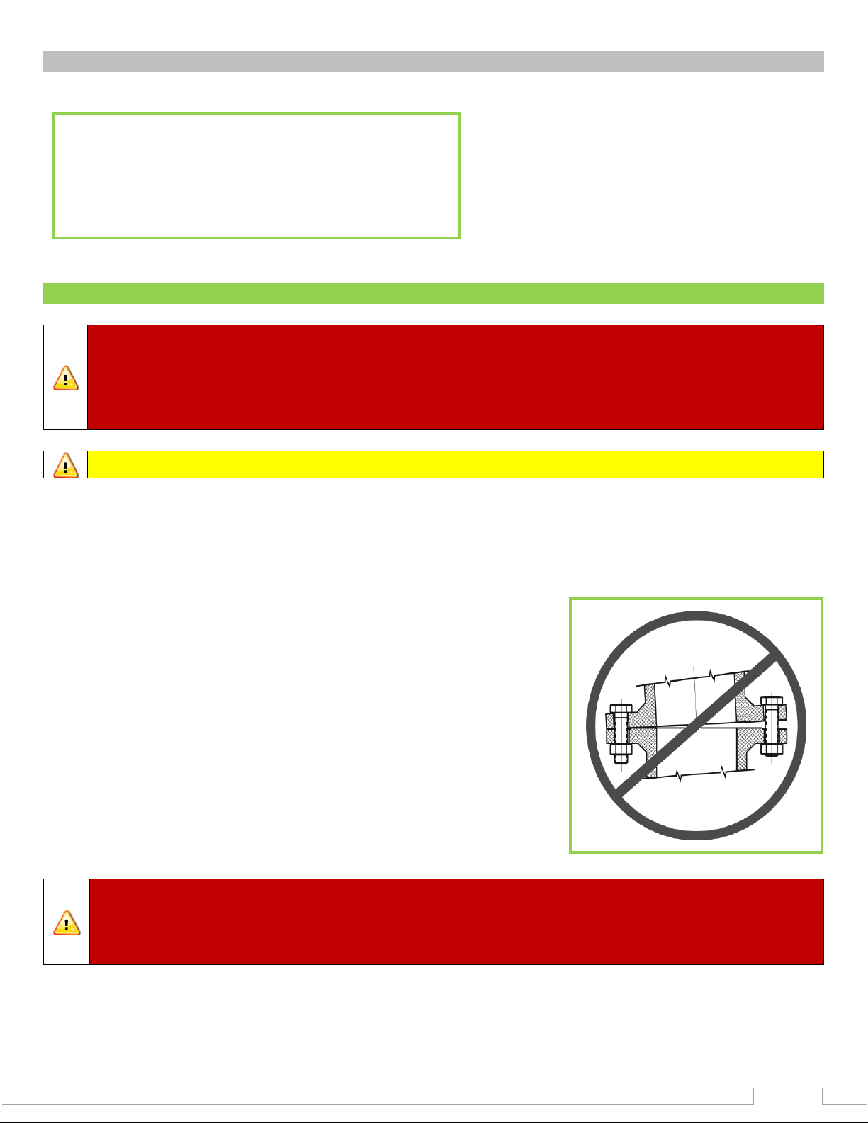
Warning: When installing the monitor on a raised face companion flange, it is critical
that the bolts be tightened uniformly to prevent misalignment of the monitor relative to
the flange or valve. If the monitor becomes misaligned, the base flange will fracture and
fail when the bolts on the “high” side are tightened.
Step 1 – Mount and Wire All System Components
Step 2 – Communication Address Setup
Step 3 – RF Settings Setup
Step 4 – System Programming
Installation Overview:
Monitor Mounting –
4” NPT Base: Thread monitor onto male 4” NPT thread using Loctite 592 or equivalent thread
sealant. Install the monitor in the straight ahead position.
4”-150# Flat Faced Flange: Attach 4”-150# ANSI pattern
companion flange to water supply pipe so that the bolt
pattern will allow the monitor to be installed in the straight
ahead position. Alignment is correct when the straight
ahead position is centered between adjacent flange holes.
Attach monitor inlet flange to companion flange on water
supply pipe with eight (8) 2½” 5/8-11 UNC grade 5,
carbon steel or stainless steel bolts & nuts. Seal flange joint
with gasket, or suitable flange sealant. Most wafer type
butterfly valves have seats that serve as flange gaskets, and
separate gaskets or sealant is not required. Apply Loctite
242 or equivalent to bolt threads before tightening nuts.
Torque to 60-70 ft-lbs.
Page 10

10
Monitor Wiring –
Crimp a fused lead from a switched positive power source to the red lead (pin C) of the power
harness supplied. Use a 10A fuse for the 8294-06 & 8294-06 EXT, and a 15A fuse for the
8394-07. Crimp a lead from the vehicle ground to the black lead (pin A) of the monitor power
harness. Shrink and seal the connectors with a heat gun after crimping.
The white lead (pin B) is for an optional “Stow Indicator” which could be attached to a relay or
LED supplied by the OEM. The circuit switches in a ground when the monitor is in a non-stowed
position.
All control functions are sent to the monitor via an encoded RF signal from the RF controller,
and no control wiring is needed.
The 8294-06 EXT has a proximity sensor. The red wire (pin C) supplies power, the black lead
(pin A) is the ground, and the white lead (pin B) is the signal for the proximity sensor to show
master stream versus an egress position.
Panel Mount RF Controllers –
Using the Panel Mount RF Controller template in the Component Mounting Templates section,
mark the panel cutout and mounting screw locations.
Cut a rectangular clearance opening and drill four (4) 7/32” holes.
Insert fixed RF controller case through the panel cutout. Secure the unit to the panel with four (4)
#10-32 screws. The length of the screws should be the panel thickness plus 3/16”. The screws
supplied are ¼” in length. Apply Loctite 242 or equivalent to screw threads before tightening
them.
The controller antenna is to be mounted using the 10’ antenna cable provided. Locate one of
the antennas outside the vehicle compartment, and in a position that provides the least
obstructed line of sight to the monitor’s antenna.
Place a 1A fuse between the red lead of the RF controller and a switched positive power lead on
the vehicle. Attach the black lead from the monitor base to the vehicle ground.
All control functions are sent to the monitor via an encoded RF signal from the RF Controller.
OEM RF Transmitter –
Place a 1A fuse between the red lead of the transmitter and a switched positive power lead on
the vehicle. Attach the black lead from the monitor base to the vehicle ground.
Connect all of the switch commons to the ground (black) connection.
Connect each function to a corresponding switch (see Table 2 on page 11). To operate the
function, close function’s switch to ground. Any combination of pushbuttons or toggle switches
can be used.
Power indication can be created by attaching an LED and proper resistance between the VCC
(+3V) and ground connections. Max rating for the VCC connection is 250mA.
The transmitter’s antenna is to be mounted using the 10’ antenna cable provided. Locate one of
the antennas outside the vehicle compartment, and in a position that provides the least
obstructed line of sight to the monitor’s antenna.
Page 11

11
Function
Wire Color
Ground
Black
VCC (+3V)
Output
Red
Right
Brown
Down
Orange
Up
Yellow
Left
Green
Stream
Blue
Fog
Violet
Aux 2
Grey
Oscillate
White
Aux 1
White/Black
Stow
White/Brown
Table 2: OEM RF Transmitter switches
Secondary Switch Box Control for Aerial Applications –
Using the Secondary Control Switch Box template in the Component Mounting Templates
section, mark the mounting holes on panel or bracket.
Drill two 9/32” diameter holes in panel or bracket.
Remove ¼-20 screws and lock washers from back of box. Insert screws with lock washers
through backside of panel or bracket into mounting holes in box. Tighten screws.
Auxiliary Battery –
Using the Auxiliary Battery template in the Component Mounting Templates section, mark
locations of mounting holes on mounting surface or bracket.
Drill four (4) 21/64” diameter mounting holes.
Open hinged cover of battery enclosure by loosening the four screws. Insert one 5/16-18 UNC
socket head cap screw from the inside of the enclosure through each of the four (4) mounting
holes of the enclosure and into the corresponding holes in the mounting surface or bracket.
Assemble nuts and lock washers to each mounting screw, then tighten.
Plug the female connector of the battery pack into the male connector at the base of the
monitor.
Crimp a fused positive power lead from the vehicle charging system to the read lead (pin C) of
the power harness supplied. Use a 10A fuse for the 8294-06 & 8294-06 EXT, and a 15A fuse
for the 8394-07. Crimp a lead from the vehicle ground to the black lead (pin A) of the monitor
power harness. Shrink and seal the connectors with a heat gun after crimping. Plug the female
connector of the finished harness into the male connector of the battery pack.
The white lead (pin B) is for an optional “Stow Indicator,” which can be attached to a relay or
LED supplied by the OEM. The circuit switches in a ground when the monitor is in a non-stowed
position.
Page 12

12
Installation Step 2: Communication Address Setup
Danger: Using two W.E.T. monitors with the same security code may cause the
inadvertent control of the wrong monitor, resulting in possible property damage and
injury to personnel. Using the factory specified codes will help prevent this.
Caution: Do NOT pinch wires when attaching back panel to front panel of the
handheld enclosure. Ensure all O-rings and gaskets are properly installed when closing
the receiver or transmitter enclosures.
Important: The RF Receiver/Control Module and all transmitter communication
addresses have been factory set. They should not require any additional address setup.
An RF Controller controls one 8294-06, 8294-06 EXT, or 8394-07 monitor. The controller is digitally
encoded with a security code ensuring that it does not accidentally control the wrong monitor. The
receiver has a matching decoder and security code that instantly decodes and interprets commands.
The security code is a 15-bit selectable code that is set on both the remote transmitter and receiver.
The 8294-06, 8294-06 EXT, and 8394-07 monitors are tested and shipped with a security code based
upon the monitor serial number, ensuring each monitor leaves the factory with a unique code assigned
to it. The security settings will normally not need to be changed. In the case of a lost transmitter or
replaced control board, contact Elkhart Brass.
Page 13

13
Installation Step 3: RF Settings Setup
1
8294-06 & 8394-07 Scorpion RF – Blinking Stow Indicator for Dash Panel Indicator
Application
2
8294-06 & 8394-07 Scorpion RF – Non-blinking Stow Indicator for Interlock
Application
A
8294-06 EXT Scorpion RF
DS5
DS2
B
A
DS1
SW4
SW1
DS4
P2
DS3
P3
DS6
P1
P4
SW2
SW3
Status LED
SW4
RF Receiver/Control Module Settings –
Remove the cover from the RF Receiver/Control Module. SW4 (see Figure 1) allows this board to be
used in different product applications. In order for it to properly operate the Scorpion RF monitor, it
must be set to one of the following positions:
If it is set to a value that is not yet programmed, the status indicator LED, DS5 (see Figure 1), will blink
rapidly until a valid setting is selected AND power is cycled. If SW4 is set to a valid setting but not one
of the above positions, unpredictable results will occur.
Figure 1: RF Receiver/Control Module Circuit Board
Handheld RF Controller Settings –
Remove the battery cover from the handheld RF controller. Remove the four (4) screws holding
the two halves of the cover together using a #1 size Pozidriv® screwdriver (use caution with a
standard Philips screwdriver as it may strip the screw heads).
Locate the security code switches on the circuit board (see Figure 2 on page 14).
Change the switches to match the settings of the RF Receiver/Control Module except switch A
position 1. One incorrect setting will prevent the system from working properly.
Ensure the battery lead connector is securely fastened to the transmitter circuit board.
When reassembling the handheld controller, ensure that no wires will be pinched, close the
cover halves, and replace the screws. Do not exceed 6 in-lbs. of torque. The screws should be
just snug. Do not over tighten the screws or the plastic enclosure could strip.
With the monitor power on, turn on the handheld controller. The PWR/XMIT light will flash.
Once the flashing light stops (light will be off), turn the handheld on once again. This can take
3-5 minutes and is required to sync the handheld to the monitor. The handheld is now ready for
use.
Page 14

14
Caution: Do NOT change switch A position 1 on any transmitter. This switch is used
to set the priority setting of the transmitter and changing this switch may remove
override capabilities.
Important: While reassembling the controller or transmitter, ensure wires and
antenna leads do not become pinched.
Figure 2: Handheld RF Controller Circuit Board
Panel Mount RF Controller and OEM RF Transmitter –
Disconnect the power connector to the panel mount controller at the back of the panel.
Open the back cover of the controller after loosening the screws.
Remove the red and black power leads from the power conversion board and place the cover to
the side.
Locate the security code switches on the circuit board (see Figure 2).
Change the switches to the settings of the RF Receiver/Control Module except switch A position
1. One incorrect setting will prevent the system from working.
Reconnect the power leads. The red lead is attached to the Positive (+) terminal, and the black
lead is attached to the Negative (-) terminal.
Close the cover and replace the screws.
Reconnect the power connector.
Page 15

15
Installation Step 4: System Programming
Programming Stow Position
Caution: To prevent damage to the monitor controller, keep all metallic objects away
from the receiver circuit board while it is energized. Ensure all O-rings and gaskets are
properly installed when closing receiver enclosure.
DS5
DS2
B
A
DS1
SW4
SW1
DS4
P2
DS3
P3
DS6
P1
P4
SW2
SW3
Red Programming
Button (SW1)
8294-06 & 8394-07
On the monitor receiver board switch A position 1 “ON” is stow up, while switch A position 1
“OFF” is stow down. If any selections are changed, power must be cycled.
Move the monitor to the left or right position that will be used for stowing the monitor.
Press and hold the red programming switch, SW1 (see Figure 3), for approximately 5 seconds,
then release.
The monitor will move up or down (depending on the location of switch A position 1 on monitor
receiver board), and rotate to the left until the stop is located.
When the monitor stops, the programming will be complete.
If the programming is interrupted by inadvertently pressing the SW1 (red) button or any button
on the primary or secondary controller, a programmed stop is set, and will not allow movement
past this point. The programmed stops can be cleared by holding the red SW1 button for 3
seconds and allowing the monitor rotate to the left stop. After this is complete, repeat the above
procedure.
On the primary controller, press and hold the Stow and Fog buttons for 5 seconds to activate
and check the stow positioning.
8294-06 EXT
The 8294-06 EXT monitor does NOT allow for user selectable stow position.
Press and hold the red programming switch, SW1, for a minimum of 5 seconds. After the red
programming button is released, the monitor will travel to both the left and right travel limits in
order to calibrate the horizontal stow position at ZERO (straight ahead).
Activating the stow function will cause the monitor to rotate to the straight-ahead position with
the discharge at 0 degree elevation.
Figure 3: SW1 Switch
Page 16

16
VERTICAL TRAVEL STOP IS FACTORY
SET AT 90 ABOVE TO 45 BELOW
HORIZONTAL
STOP SCREWS ARE FACTORY
INSTALLED AT THESE LOCATIONS.
(180 HORIZONTAL TRAVEL.)
Rotational Limit Settings
8294-06
The rotational stop screws (see Figure 4) set the monitor rotational limits (left-right and up-down)
to satisfy the application requirements, as well as NFPA* requirements. The monitor is shipped
from the factory with the horizontal travel limits set at 90 degrees left and 90 degrees right of
the zero (straight ahead) position. The vertical travel limits are factory set at 90 degrees above,
and 45 degrees below horizontal. If the application requires the rotation limits to be changed,
relocate threaded stop screws to required positions per chart below. Apply Loctite 242 or
equivalent to stop screws and hex head plugs prior to reinstalling (stop screw holes are identified
on the monitor by a stamped letter adjacent to each hole). All empty stop screw holes should be
filled with a hex head plug.
8394-07
The rotational stop screws (see Figure 4) set the monitor rotational limits (left-right and up-down)
to satisfy the application requirements, as well as NFPA* requirements. The monitor is shipped
from the factory with the horizontal travel limits set at 90 degrees left and 90 degrees right of
the zero (straight ahead) position. The vertical travel limits are factory set at 90 degrees above,
and 45 degrees below horizontal. If the application requires the rotation limits to be changed,
relocate threaded stop screws to required positions per chart below. Apply Loctite 242 or
equivalent to stop screws and hex head plugs prior to reinstalling (stop screw holes are identified
on drawing 98031050). All empty stop screw holes should be filled with a hex head plug
8294-06 EXT
Monitor can be rotated 90° left or 90° right of the zero (straight ahead) position. The vertical
travel is either Master Stream (+30 to -135°) or Egress (+0° to -135°). Horizontal travel limits
can NOT be changed.
Monitor can be rotated 90° left or 90° right of straight ahead. Stops are mechanically fixed by a
stop screw and milled slot in base. Stop screw must remain in place in monitor base.
Figure 4: Scorpion RF Rotational Stops
Page 17

17
Caution: At least one stop screw is required to prevent damage to the monitor. If the
monitor is set with the horizontal setting at 174 degrees left or right of the zero (straight
ahead) position, the vertical setting will need to be set to 30 degrees below horizontal as
the maximum lowest position.
Application
Rotation Limits
Stop Screw
Locations
Aerial Ladder,
Elevating Platform,
Water Tower
45° Left or Right of Straight Ahead
D & H
67½° Left or Right of Straight Ahead
E & G
90° Left or Right of Straight Ahead
F
Deck Gun
174° Left or Right of Straight Ahead
A
Application
Rotation Limits
Stop Screw
Locations
Aerial Ladder,
Deck Gun
90° above horizontal to 45° below horizontal
T
Elevating Platform
45° above horizontal to 45° below horizontal
T & U
20.6
Aerial Ladder Water Delivery System
20.6.1.3.1
The monitor shall be capable of swiveling at least 135° from a line parallel to the
ladder and down.
20.6.1.3.2
The monitor shall be capable of horizontal traverse at least 45° from each side of
center.
20.12
Elevating Platform Water Delivery System
20.12.3.2
The monitor(s) shall allow the operator to control the aimed direction of the nozzle
through a rotation of at least 45° on either side of center and at least 45° above and
below horizontal.
20.12.3.3
The horizontal and vertical traverse of the monitors shall not exceed the elevating
platform manufacturer’s recommendation.
Table 3: Horizontal Settings (8294-06 only)
Table 4: Vertical Settings (8294-06 only)
To view a complete list of stops, please download the Scorpion Monitor Position Chart (98031010 for
8294-06, and 98031050 for 8394-07) from www.elkhartbrass.com.
Table 5: NFPA 1901, 2003 Ed. minimum rotation angles for aerial device monitors.
Page 18

18
OPERATING INSTRUCTIONS
Normal Operation
The Scorpion monitors use the standard Left/Right, Up/Down, and Fog/Stream commands to provide
stream direction and pattern adjustments.
To move the monitor left or right, press and hold the LEFT or RIGHT button until the monitor
discharge is in the correct position, or a mechanical stop is reached.
To move the monitor up or down, press and hold the UP or DOWN button until the monitor
discharge is in the correct position, or a mechanical stop is reached.
To adjust the stream pattern, press and hold the FOG or STREAM button until the desired stream
pattern is reached.
Any combination of left or right, fog or stream, and up or down can be used to achieve motion
horizontal, vertical, or nozzle commands simultaneously. If the LEFT and RIGHT buttons are pressed at
the same time, the monitor will stop all motion. To continue motion, release both buttons and repress
the desired direction button. This is also true for the up/down and fog/stream commands.
The handheld remote transmitter has a power saving feature that turns the transmitter power off if no
signal is sent for 5 minutes. Press and hold the “ON/OFF” button until the Power LED illuminates to
reactivate the transmitter. The “Low Battery” LED will flash slowly when the battery voltage drops below
a predetermined level. When the low battery LED flashes rapidly, the batteries are nearly discharged
and should be replaced immediately.
NOTE: The SM-1250E, SM-1250BE, SM-2000E and SM-2000BE nozzles have a unique ball screw
drive that allows motor to “free wheel” at the end of pattern travel in either the straight stream or wide
fog positions. No slip clutch or current limiting feature is used with these nozzle drives.
Oscillation Function
The 8294-06, 8294-06 EXT, and 8394-07 monitors have an automatic left/right oscillation function,
which can be used to provide continuous exposure protection with no operator input. The oscillation
limits are set using the handheld or truck mount RF transmitters.
Position the monitor at either the left or the right limit of oscillation.
Press and hold the OSCILLATE button.
Move the monitor to the other limit of oscillation.
Release the OSCILLATE button.
Press and release the OSCILLATE button to engage the oscillation function.
The monitor will oscillate between the limits until the oscillation button is pressed again. Pressing
the left or right button on one of the controllers will also stop the oscillation.
For safety reasons, once oscillation has stopped the oscillation limits need to be reprogrammed before
it can be re-engaged. The nozzle fog, stream, and discharge elevation functions can be operated
while the monitor is oscillating.
Page 19

19
Important: Using the horizontal override nut when the power to the receiver is off or
the horizontal motor is disconnected will move stow position from its original
programmed position. See section titled Programming Stow Position to realign stow
position even if stow feature is not utilized.
Warning: Do NOT use impact drivers to operate the manual override nuts. Serious
damage to motor gear heads will occur.
Manual Override
In the event of power failure to the monitor, the motors may be actuated manually. To operate a
function manually, simply apply a ¾” ratcheting type wrench (either socket type or ratcheting box end
type) to the hex fitting on the motor shaft.
Storing the Monitor
Elkhart Brass recommends that a stow position be set and the stow routine be utilized to place the
monitor in its stowed position after each use.
8294-06 & 8394-07
These monitors have a user selectable stow position (see Programming Stow Position section for
instructions). After the water supply to the monitor has been turned off, simultaneously press the
STOW and FOG buttons on the primary panel mount RF transmitter (buttons must be held down
for a minimum of 3 seconds). The monitor will automatically rotate horizontally to the stow
position previously programmed, and either lower or raise the discharge to its mechanical stop
(depending on the position of switch A position 1 on the receiver board). Prior to stowing the
monitor, the stow signal output provides a ground signal. There are two settings for stow signal
output.
Switch 4 Position 1 (Signal Mode)
Once the monitor starts to move to the stow position, the stow signal output will alternately
supply and remove the ground, at approximately a 1 second rate, while the monitor is moving
to the stow position. Once the monitor has completed the stow sequence, the stow signal output
will be an open circuit.
Switch 4 Position 2 (Interlock Mode)
Once the monitor starts to move to the stow position, the stow signal output will continue to
supply a ground while the monitor is moving to the stow position. The ground will be removed
after the monitor reaches the stow position and the stow signal output will be an open circuit.
NOTE: If the stow indicator does not turn off, see the Programming Stow Position section to
realign the stow position. Provided the necessary switches are wired, the OEM primary
transmitter will operate using the same inputs as listed for the primary panel mount transmitter.
Any directional command (left, right, up, down, fog or straight stream) will cancel the stow
command, and the stow output signal will continue to provide a ground. To stow the monitor,
the stow command must be reactivated.
Page 20

20
Warning: Never activate the stow feature while water is flowing. Serious injury to
personnel and damage to apparatus could result.
Warning: It is up to the system designer to appropriately handle the open circuit
condition of the stow signal. In the open circuit mode there is no source to turn off the
stow signal load, which may lead to erroneous signal indications if not handled properly.
The stow signal is capable of sinking 250mA maximum. Exceeding this value may blow
the internal fuse and the stow output will no longer be able to provide a ground.
Important: Most test lights draw in excess of 1A.
8294-06 EXT
The 8294-06 EXT aerial monitor does not allow for a user selectable stow position, switch SW4
should be set to position A for this application. After the water supply to the monitor has been
turned off, simultaneously press the STOW and FOG buttons on the primary panel mount RF
transmitter (buttons must be held down for a minimum of 3 seconds). Activating the stow
function causes the monitor to rotate horizontally to the center of the allowed travel and move
the discharge to 0° elevation. As the monitor starts to move to the stow position, the stow signal
output will continue to supply a ground while the monitor is moving to the stow position. The
ground will be removed after the monitor reaches the stow position and the stow signal output
will be an open circuit.
Any directional command (left, right, up, down, fog or straight stream) will cancel the stow
command, and the stow output signal will continue to provide a ground. To stow the monitor,
the stow command must be reactivated.
Page 21

21
MAINTENANCE & INSPECTION
Monitor
Caution: DO NOT use high pressure spray to clean the monitor system. Using high
pressure spray can damage seals and lead to serious damage of electrical components.
Caution: Always check the stow position after any repairs to the monitor. It is
possible that during repair work the stow position could be moved or lost, and will need
to be reprogrammed. If necessary, reprogram the stow position by following the
instructions in the Programming Stow Position section.
Preventive Maintenance
The complete monitor and control system should be inspected during each apparatus check. Careful
inspection for damage to the monitor or nozzle is especially important after use of the Scorpion RF
monitor in emergency operations.
Operate all possible functions to ensure that each works normally.
Flow water to check the nozzle pattern.
o If the pattern is disrupted, remove the nozzle and check for debris lodged between the nozzle
stem and body, or in the stream shaper inlet. Remove debris.
During nozzle flow test, inspect monitor swivel joints for leaks.
With the water off, operate the stow function, looking for any possible obstructions and check
the final stow position.
Inspect all exposed wiring for signs of damage.
Note: Although grease fittings are provided for the up-down and left-right gear cases, routine greasing
should not be necessary. If the monitor is exposed to high level of radiant heat for a prolonged period,
it may be possible for the factory grease to thin and run out of the gear cases. In such an event, fresh
grease should be applied. It is recommended that Mobilith AW2 grease be used to lubricate the
monitor gearing.
Page 22

22
Reference
Indication
Meaning
1
Blinks 6 times rapidly during startup
Visual indication that the controller is
initializing – normal operation.
2
Blinks 6 times rapidly during startup, then
blinks at ¼ second rate continuously
SW4 in wrong position – must be in position 1
or 2 for proper 8294-06 or 8394-07, or
position 3 for 8294-06 EXT operation.
3
Blinks at ½ second rate
Truck battery voltage <8 volts – light will blink
until power is lost or restored.
DS5
DS2
B
A
DS1
SW4
SW1
DS4
P2
DS3
P3
DS6
P1
P4
SW2
SW3
Figure 5: System LED Notations
Understanding System LEDs
LED Notations
o DS1 – Lights when either nozzle direction is engaged.
o DS2 – Lights when either of the AUX buttons are pushed.
o DS3 – Comes on when the UP or DOWN button is pressed.
o DS4 – Comes on with any horizontal movement.
o DS5 – See DS5 Status Indicator Table below.
o DS6 – Lights when power is applied.
Table 6: DS5 Status Indicator LED Table
Page 23

23
Handheld Controller
Battery Type
The Scorpion handheld controller uses two AA Lithium batteries. The low battery light will illuminate
with approximately two hours of transmission time remaining before the batteries are completely
discharged. Due to the time-voltage characteristics of rechargeable batteries, this time could be
drastically reduced if rechargeable batteries are used.
Battery Replacement
The batteries can be replaced with any standard fresh AA Lithium batteries.
Turn the controller power off.
Remove the battery cover.
Remove both of the old AA batteries.
Wait 5 minutes, and then install new AA Lithium batteries.
Replace the battery cover.
Page 24

24
SYSTEM SPECIFICATIONS
Monitor
Left/Right
Up/Down
Nozzle
Run Current*
5 A
6 A
0.5 A
Stall Current*
26 A
26 A
NA
Current Trip Point*
13 A
10 A
4 A
Table 7: Motor Current Specifications
*All current ratings are at 12V
Panel Mount Controller
Input power 12/24 VDC (11 VDC to 30 VDC)
RF power output Meets FCC part 15 requirements for license free operation
Transmitter dimensions 7 5/8” x 3 7/8” x 2 3/8”
Operating temperature range -40
o
C to +65oC, -40oF to +150oF
Environmental Rating NEMA 4
FCC ID QT8PTSS2003
Handheld Controller
Input power 2 AA Batteries (Lithium Recommended)
RF power output Meets FCC part 15 requirements for license free operation
Transmitter dimensions 6” x 3 1/4” x 1 3/8”
Transmitter weight 10 ½ oz.
Operating temperature range -40
o
C to +65oC, -40oF to +150oF
Environmental Rating NEMA 4
FCC ID QT8PTSS2003
Receiver
Power requirements Without Converter Assembly 12VDC (11-14VDC)
Electrical Load See Table 7 Below
Control current 0.07 A (12V)
Operating temperature range -40
o
C to +65oC, -40oF to +150oF
Environmental Rating NEMA 4
Shock
30 G’s (55 Hz. @ .2” double amplitude)
Vibration
15.5 G’s (55 Hz. @ .05” double amplitude) continuous operation
Drop Test
The handheld controller must meet operating specifications after drop from 1m height onto
concrete surface.
Environmental
All enclosures have a NEMA 4 rating (must withstand a 1” stream of water at 65 GPM from a
distance to 10ft. for five minutes with no water entering the enclosure).
Page 25

25
MONITOR AND NOZZLE HYDRAULIC DATA
ΔP
S
= HF + ΔP
V
ΔP
S
= Total Static Pressure Drop
HF = Friction Loss
ΔP
V
= Velocity Pressure Loss
Interpreting Flow Data
The following graphs offer the pressure losses for the monitor (and other devices) in terms of Total
Static Pressure Drop. This Total Static Pressure Drop can be found by measuring the difference
between the static inlet pressure and the static outlet pressure. The static pressure at either of these
points can be found using a simple pressure gauge. An illustration of this method can be seen below.
In mathematical terms, the Total Static Pressure Drop is the change in Velocity Pressure plus Friction
Loss. The change in Velocity Pressure results from the change in velocity of water caused by the
change in the cross section of a waterway. Friction Loss results from the drag and sidewall interference
of the water through a device. A simple equation can be seen below.
In the firefighting industry, the terms Total Static Pressure Drop and Friction Loss tend to be used
interchangeably. However, these are significantly different measurements. This misconception could
ultimately lead to lower than anticipated performance from equipment. When designing a system and
determining performance, Total Static Pressure Drop is the value that should always be used. The
Friction Loss curve is also supplied in order to make a comparison with competitor products that may
only supply Friction Loss curves. If there are any further questions regarding this matter, please contact
Elkhart Brass.
Page 26

26
Scorpion RF Monitor Losses
4.0" Inlet and 3.5" Outlet
0
10
20
30
40
50
60
0 200 400 600 800 1000 1200 1400 1600 1800 2000
Flow Rate (GPM)
Pressure (PSI)
Total Static Pressure Drop Friction Loss
50 60 65 70 75 80 50 60 65 70 75 80
SS
110 140 172 220 229 -
NARROW FOG
100 129 132 136 140 -
WIDE FOG
56 62 68 72 82 -
SS
- - - - 240 300
NARROW FOG
- - - - 125 148
WIDE FOG
- - - - 90 100
EFFECTIVE REACH in FEET
NOZZLE PRESSURE PSI
NOZZLE DISCHARGE U.S. GPM
CATALOG NO.
INLET
SIZE
STREAM
SETTING
NOZZLE PRESSURE PSI
SM-1250E
1100
1250-3.5
385
655
875
-
SM-2000E
3.5
500
850
1250
1500
2000
Page 27

27
COMPONENT MOUNTING TEMPLATES
IF YOU CAN SEE THIS TEXT, PLEASE REPRINT THIS PAGE AT 100% (N
OT SCALED) FROM THE DIGITAL PDF. DOUBLE CHECK BEFORE DRILLING.
IF YOU
CAN SEE THIS TEXT, PLEASE REPRINT THIS PAGE AT 100% (N
OT SCALED) FROM THE DIGITAL PDF. DOUBLE CHECK BEFORE DRILLING.
NOTE: Pages must NOT be scaled during printing or template size will be scaled incorrectly.
Panel Mount Controller Mounting Template
Page 28

28
2.05
0.55
3.15
0.244.45
4.92
0.281-DRILL THRU
2-HLS. REQ'D.
IF YOU CAN SEE THIS TEXT, PLEASE REPRINT THIS PAGE AT 100% (N
OT SCALED) FROM THE DIGITAL PDF. DOUBLE CHECK BEFORE DRILLING.
IF YOU CAN SEE THIS TEXT, PLEASE REPRINT
THIS PAGE AT 100% (N
OT SCALED) FROM THE DIGITAL PDF. DOUBLE CHECK BEFORE DRILLING.
Secondary Control Switch Box Mounting Template
Page 29

29
IF YOU CAN SEE
THIS TEXT, PLEASE REPRINT THIS PAGE AT 100% (N
OT SCALED) FROM THE DIGITAL PDF. DOUBLE CHECK BEFORE DRILLING.
IF YOU CAN SEE THIS TEXT, PLEASE REPRINT THIS PAGE AT 100% (N
OT SCALED) FROM THE DIGITAL PDF. DOUBLE CHECK BEFORE DRILLING.
Auxiliary Battery Mounting Template
Page 30

ELKHART BRASS
1302 WEST BEARDSLEY AVE
P.O. BOX 1127
ELKHART, IN 46514
PHONE: 1-574-295-8330 • 1-800-346-0250
FAX: 1-574-293-9914
WWW.ELKHARTBRASS.COM
© ELKHART BRASS MFG. CO., INC. 2014
8294-06, 8294-06 EXT, 8394-07 MONITORS
INSTALLATION, OPERATION, AND MAINTENANCE INSTRUCTIONS
98291000 REV. J
 Loading...