

Page 1

E
E
LLKKHHAARRTT
B
B
RRAASSSS
M
M
FFG
G
.
.
C
C
O
O
..,
,
I
I
NNC
C
..
1302 WEST BEARDSLEY AVENUE P.O. BOX 1127 ELKHART IN 46515 (574) 295-8330 FAX (574) 293-9914
Installation, Operating, &
Maintenance Instructions
Model 8297 RF
Break-Apart Deck Gun/Portable Radio
Controlled Monitor & Accessories
98308000 Rev. F
Page 2

Page 3

Table of Contents
I. Product Safety.................................................................................................................. 1
II. SYSTEM FEATURES ................................................................................................... 2
III. SYSTEM COMPONENT DESCRIPTIONS ................................................................ 4
A. 8297 RF Upper Monitor ........................................................................................... 4
B. 8298 RF Deck Mount Adapters ............................................................................... 7
C. Portable Bases .......................................................................................................... 7
D. 8297MB-RF Storage Bracket................................................................................... 7
E. RF Transmitters ........................................................................................................ 8
81282001 Handheld RF Transmitter (Figure 8) ......................................................8
81327111 Panel Mount Primary Transmitter ..........................................................8
81353101 OEM Primary Transmitter ......................................................................8
IV. Control System Specifications .................................................................................... 10
V. Installation Instructions ................................................................................................ 11
A. 8298F RF Deck Mount Adapter............................................................................. 11
B. 8298P RF Deck Mount Adapter ............................................................................. 12
Power Cable Wiring ...............................................................................................12
81327111 Panel Mount Transmitter ......................................................................13
81353101 Fixed OEM Supplied Switches .............................................................14
C. Communications Address Setup ............................................................................ 14
Monitor Settings.....................................................................................................15
81282001 Handheld Transmitter Settings .............................................................16
81327111 and 81353101 Panel Mount and OEM Transmitters ............................17
VI. Operation .................................................................................................................... 18
A. Deck Gun Mode ..................................................................................................... 18
1. Attachment and Operation .................................................................................18
2. Monitor Removal from base ..............................................................................18
B. Portable Monitor Mode .......................................................................................... 19
C. Normal Operation ................................................................................................... 20
D. Oscillation Function ............................................................................................... 21
E. Manual Override ..................................................................................................... 21
F. Power Switch .......................................................................................................... 22
VII. Maintenance .............................................................................................................. 23
A. Preventive Maintenance Procedures for Stinger RF Upper Assembly .................. 23
Preventive Maintenance .........................................................................................23
After Each Use: ......................................................................................................23
As Needed: .............................................................................................................24
B. Maintenance Procedures for Stinger RF® Bases .................................................... 24
After Each Use: ......................................................................................................24
As Needed: .............................................................................................................25
Understanding the Controller LEDs ......................................................................25
Handheld Transmitter ............................................................................................25
Battery Type...........................................................................................................25
Replacing the Battery .............................................................................................25
VIII. Monitor & Stream Shaper Hydraulic Data .............................................................. 26
Interpreting Flow Data ................................................................................................ 26
Page 4

1
I. PRODUCT SAFETY
Important:
Before installing and operating this equipment, read & study this manual thoroughly.
Proper installation is essential to safe operation. In addition, the following points should
be adhered to in order to ensure the safety of equipment and personnel:
All personnel who may be expected to use this equipment must be thoroughly trained in
its safe and proper use.
Before flowing water from this device, check that all personnel (fire service and civilian)
are out of the stream path. Also, check to make sure stream direction will not cause
avoidable property damage.
Become thoroughly familiar with the hydraulic characteristics of this equipment, and the
pumping system used to supply it. To produce effective fire streams operating personnel
must be properly trained.
Open water valve supplying this equipment slowly, so that piping and hose lines fill
slowly, thus preventing possible water hammer occurrence.
After each use, and on a scheduled basis, inspect equipment per instructions in section
VII.
Always determine that latch pins are fully engaged (see Figure 16 on pg. 18).
The maximum monitor flow capacity is 1250 gallons per minute with most base adapters
(the clappered Siamese inlet is rated at 1000 GPM).
Always secure the monitor with the safety strap in portable mode.
Never attempt to move the portable monitor while flowing water.
Whenever possible, this equipment should be operated from a remote location. Do not
needlessly expose personnel to dangerous fire conditions.
Always inspect the ground spikes for damage after each use.
Any modifications to the electrical enclosures will destroy the NEMA 4 rating and void
warranty coverage of the enclosure and all components within.
Warning: X-Streams are extremely powerful. Therefore, great care must be
taken in directing such streams to avoid injury to personnel and unwanted damage to
property.
Page 5
2
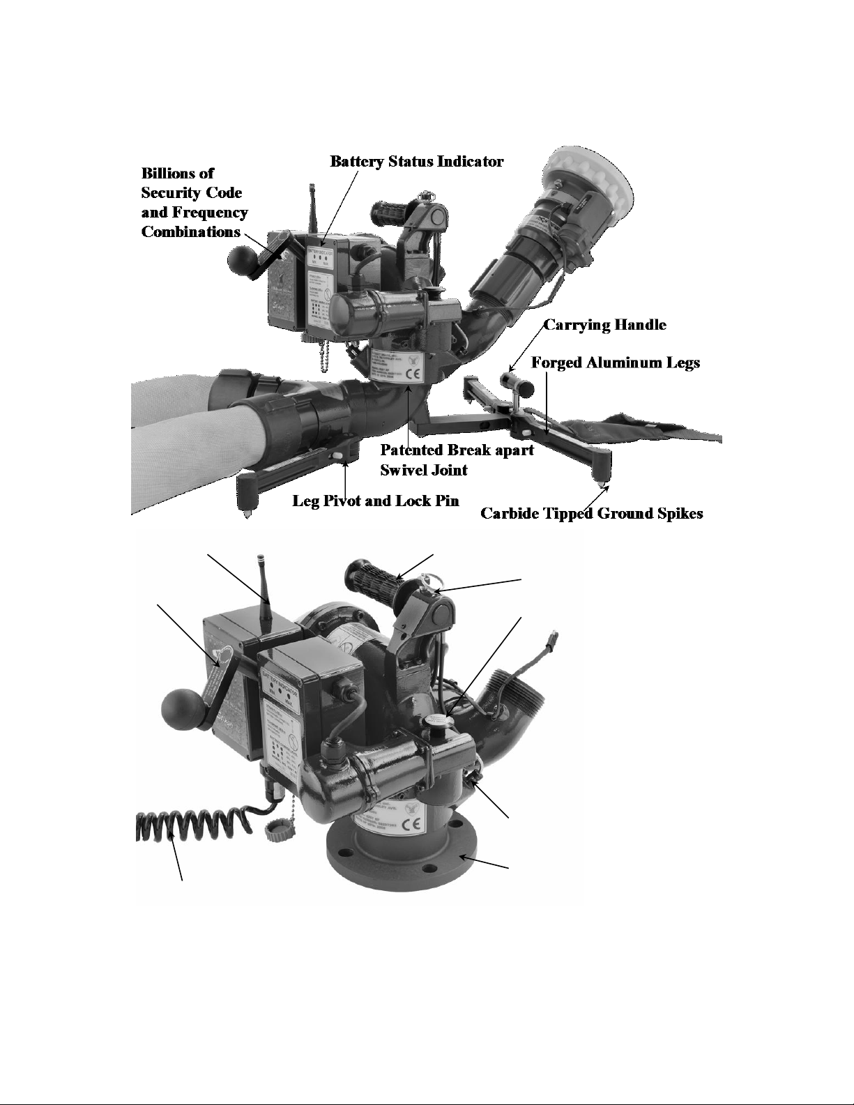
II. SYSTEM FEATURES
Twist Release/Handle
Left/Right Override
Up/Down
Override
Twist Release Lock Pin
Latch Pin Visual Indicator
150#ANSI Flange
Up to ¼ Mile Range
Power Harness
Figure 1
Stinger RF on 2-Inlet Portable Base and on Deck Mount Base
Page 6
3
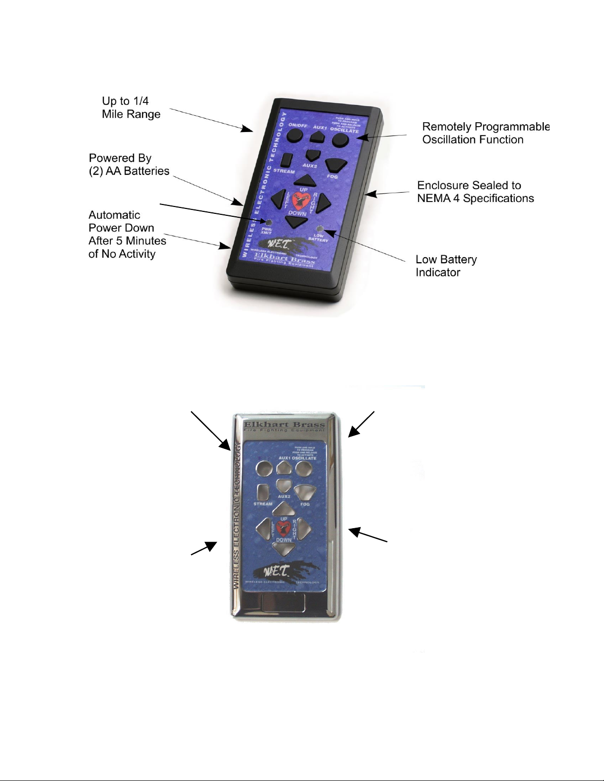
NEMA 4 Sealed
No Control
Wires to
Run
Flush
Mount
Hardwired to
Vehicle Power
System
(Maximum
current draw is
500 mA)
Power Indicator
Figure 2
81282001 Handheld Transmitter Features
Figure 3
81327111 Panel Mount Control Features
Page 7
4
III. SYSTEM COMPONENT DESCRIPTIONS
A. 8297 RF Upper Monitor
The 8297 Stinger RF® Portable Monitor is a lightweight dual-purpose monitor. The
highly efficient cast aluminum waterway contains a central vane to minimize large-scale
turbulence and provide superior fire streams. The patented break-apart swivel joint
allows one upper assembly to be used with either of two truck mount adapters or one of
the many portable bases. Nozzle stream direction is controlled by two permanent magnet
type gear motors, one controlling rotation about the axis of the water inlet, and the other
controlling nozzle elevation and depression. The maximum monitor flow capacity is
1250 gallons per minute with most base adapters (the clappered Siamese inlet is rated at
1000 GPM).
Stinger RF® monitors are normally supplied with the 282A stream shaper and the SM1250E constant pressure (automatic) type master stream nozzle. The ST-194-A Stacked
Tip combination is also available for use with the Stinger RF®.
The following additional features are also provided in the Stinger RF® monitor:
Twist Release Handle and Lock Pin
The twist release handle makes a convenient carrying handle for both the Stinger RF®
upper and the Stinger RF
conversion from the deck mode to portable base mode. The lock pin ensures that the user
does not accidentally activate the twist release handle while carrying the Stinger RF®
attached to the portable base.
Elevation Stop
The electronic elevation stop automatically limits the nozzle to a minimum elevation of
30 when in portable mode.
®
with a portable base attached. It also provides for a quick
Warning: Using the Up-Down over-ride while in portable mode can cause
serious injury or death to nearby personnel. Use extreme caution when using this
feature. The minimum elevation angle should be no less than 30, and the portable base
must be securely anchored using the attached strap.
Latch Pin Visual Indicator (See Figure 4)
The visual indicator is used to
quickly determine when latch pins
are engaged. When the latch pins are
properly engaged, no part of the pins
should be visible in the indicator
cutout of the latch pin cap.
Figure 4
Latch Pin
Page 8

5
Manual Overrides
The Stinger RF is equipped with manual override features for both the Up-Down and
Left-Right functions. These overrides are intended for use in the event of power failure,
or when a remote transmitter is not readily accessible.
Left-Right: To move the monitor left or right manually, push down and hold the
spring-loaded knob with the right hand while grasping the return bend with the
left hand. Using the left hand, either push to move the monitor to the right, or pull
to reposition to the left. Please note that the left-right motor drive unit reengages
only every 90. There is no left-right locking feature while the motor drive is
disengaged; keep a hand on the return bend in order to maintain stream position.
Up-Down: A hand crank mechanism is provided to allow manual control of the
nozzle elevation. As a safety feature to prevent hand and finger injuries, this
crank handle is always disengaged from the motor drive unit. To engage the
crank handle (and simultaneously disengaged motor drive), push in on ball knob
in a direction parallel to the hand-wheel shaft. While holding the ball knob in,
turn crank in direction indicated on handle label to either raise or lower nozzle.
When on portable base, never position nozzle at less than 30°.
Safety Switch (See Figure 5)
The Stinger RF has a safety switch
feature to prevent remote operation of
the unit when it is not attached to either
the deck mount or portable base. This
feature is designed to prevent possible
serious finger injury due to entanglement
in the left-right drive gearing located
within the inlet area of the upper monitor
assembly.
Figure 5
Safety Switch
RF Receiver/Control Module
The monitor control circuit uses a state-of-the-art PIC (Programmable Integrated Circuit)
chip design. This device allows numerous control features while keeping circuit board
size to a minimum. Relays within this box provide motor reversing control for the
Up/Down, Left/Right and Straight Stream/Fog functions.
All functions are sent to the RF Receiver/Control Module via an encoded radio frequency
link. The radio link reduces the number of wires to just the two power leads for battery
charging, dramatically simplifying the installation procedure. The link allows wireless
control from up to ¼ mile away.
An encoder, part of the left/right motor, provides left/right motion control feedback. The
encoder allows the user to set endpoints at any combination of horizontal angles. The
counter in combination with the PIC controller enables the monitor to oscillate between
these endpoints.
The control system also provides secondary motor protection with the use of electronic
current sensing circuitry. If the monitor encounters an obstruction before reaching a
limit, this circuitry quickly senses motor stall current and automatically shuts off power
Page 9
6
to the motor. As soon as the control switch is released, the circuit resets to allow
subsequent operation of the monitor.
Caution:
Any modification of the enclosure will destroy the NEMA 4 rating and will void the
warranty coverage of the Transmitter.
The following additional functions/features are provided in the RF Receiver/Control
Module:
Reverse Polarity Protection: If battery connections are reversed, this
feature prevents power from being applied to circuits, and prevents
damage to electronic components.
Circuit Board Moisture Protection: The circuit board and circuit components
are protected from moisture by an acrylic resin conformal coating. All relays
have sealed covers.
Battery Enclosure (See Figure 6)
The battery enclosure contains a 5 A/H
lead-acid battery, battery charging
that the charging voltage is less than the
battery voltage.
circuitry, and an LED battery charge
status indicator. This indicator displays
the source of power and the amount of
charge on the battery. A steady LED
means that truck power is connected and
the battery is charging. A flashing LED
signifies that truck power is
disconnected. A green LED signifies
80% to a full charge of the battery. A
yellow LED shows a 40%-80% charge
of the battery. A red LED signifies a
20% - 40% charge. If one LED is on
solid indicating a charging operation and
then all three LEDs blink; this means
Figure 6
Battery Enclosure
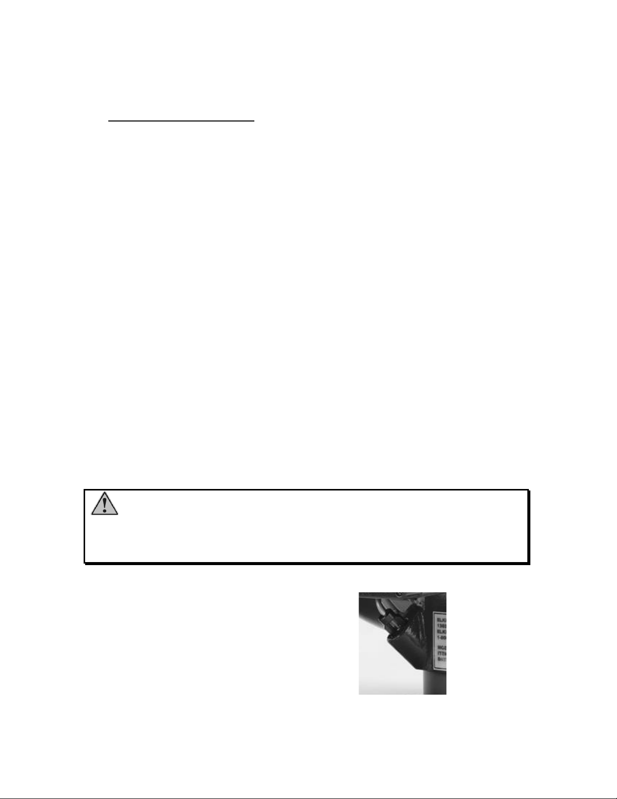
Power Cable (See Figure 7)
The power cable (P/N 36846000)is a
three conductor coiled self-retracting
cable that provides for battery charging,
and allows operation of the monitor as a
monitor control processor senses the
presence or absence of the power cable,
and thus determines the appropriate
allowable up-down travel range.
deck gun while powered by the vehicle
electrical system. A bayonet style
connector allows convenient attachment
and removal of the cable from the power
receptacle located on the bottom of the
RF Receiver/Control Module. The
Figure 7
Power Cable
Page 10

7
Warning: Before removing the Stinger RF upper unit from the deck mount
There are six optional portable bases with self-aligning ring gear available:
1. Two 2.5” clappered female swivel inlets
2. One 3.5” swivel inlet
3. One 4.0” swivel inlet
4. One 4.5” swivel inlet
5. One 4.0” Storz inlet
6. One 5.0” Storz inlet
for use in portable mode, disconnect the power cable.
A power charging harness (P/N 5255700) is provided with the monitor system. It is used
to charge the internal battery on a portable base.
B. 8298 RF Deck Mount Adapters
The 8298 RF deck mount adapter allows use of the 8297 RF as a deck gun, and is
designed for a pre-plumbed pipe directly from the apparatus pump. The 8298F RF
adapter consists of the 3” 150# flat faced ANSI flange, cast waterway, swivel ring, and
either a full or partial rotation gear ring. The 8298P RF adapter consists of the 3” NPT
female thread, wrought waterway, swivel ring, and either a full or partial rotation gear
ring.
Elkhart Brass offers a 3” companion flange kit (part no. 81315001) to be used with the
8298 RF deck mount adapter. The kit consists of an ANSI 3” 150# flange, four 5/8 – 16
bolts with nuts, and a 3” gasket.
C. Portable Bases
The portable base support legs can be folded for compact storage in an apparatus
compartment or hose bed pre-connected to a supply hose line. The folding legs are
designed to be easily rotated from the stored position to the extended and locked position
and back again. The spring-loaded carbide ground spikes are very hard and very sharp,
important factors in the prevention of sliding under flow.
The anchor kit (Part #81460001) is used to safely secure the monitor with a steel stake
and safety strap. The Stinger RF should always be anchored when it is in the portable
mode. The kit also includes a Nupla® 4lb. Hammer with safety grip fiberglass handle,
and a nylon carrying bag.
D. 8297MB-RF Storage Bracket
The 8297MB-RF is an optional, lightweight bracket that is designed to hold the Stinger
RF® securely in place while in storage. The 8297MB-RF can be used to store the
complete monitor or the portable base separate from the upper monitor. A single release
lever allows for fast and efficient removal of the unit from the storage bracket. The
bracket can be mounted either horizontally or vertically. (Not intended to be used while
flowing water.)
Page 11

8
E. RF Transmitters
81282001 Handheld RF Transmitter (Figure 8)
A sealed handheld radio remote contains all the controls
necessary for operation of the monitor. The handheld
remote allows the operator to direct the monitor from a
significantly improved point of view. With the wireless
remote, the operator can view the stream from the side and
confirm that the stream is hitting its target. Separate push
button switches are provided for up, down, left, right, fog,
and stream functions. The handheld rem0otes have user
selectable security codes that allow multiple transmitters
and monitors to operate on the same fireground at the
same time. The remote has an automatic power down
feature that will shut down the power after 5 minutes of no
activity. As an additional power saving feature the radio
signal is only transmitted while a button is pushed. The
handheld remote case has a NEMA 4 rating.
Figure 8
81282001 Handheld Transmitter
81327111 Panel Mount Primary Transmitter
(Figure 9) The fixed transmitter sends signals to the
monitor via an encoded radio signal, requiring no wires
between the transmitter and the monitor. It is powered by
the 12V vehicle electrical system. The faceplate is
intended for a flush mount onto the pump control panel.
Separate sealed push button switches are provided for up,
down, left, right, fog, and stream functions. It will override
any handheld control, allowing the apparatus operator to
retain ultimate control over the monitor. Comes with 10
foot coax antenna cable and (1) 90° antenna and (1) straight
antenna.
Figure 9
81327111 Panel Mount Primary
Transmitter
81353101 OEM Primary Transmitter
(Figure 10) The OEM Transmitter allows the OEM to use
their own switching arrangement while still providing the
benefits of W.E.T. It has all of the same features of the
Primary Panel Mount Transmitter, but has a wiring harness
for the installer to connect to OEM supplied switches.
Comes with 10 foot coax antenna cable and (1) 90°
antenna and (1) straight antenna.
Figure 10
81353101 OEM Primary Transmitter
The 8297 RF monitor uses W.E.T. (Wireless Electronic Technology), an innovative
wireless radio link, to send all commands from the RF Transmitters to the RF
Receiver/Control Module. This new wireless link gives the operator the ability to
view the discharge stream and target from virtually any point of view from up to ¼
mile from the monitor.
Page 12

9
Caution:
Any modification of the enclosure will destroy the NEMA 4 rating and will void the
warranty coverage of the transmitter.
Caution:
Do not pinch wires when attaching back panel to front panel of enclosure of handheld
control. Ensure all O-rings and gaskets are properly installed when closing receiver or
controller enclosures.
Page 13

10
Input power
2 AA batteries (Alkaline recommended)
Output power
Meets FCC part 15 requirements for license free
operation
Transmitter dimensions
6” x 3 1/4” x 1 3/8”
Transmitter weight
10 ½ oz.
Operating temperature range
-40F to 150F (-40C to 65C)
FCC ID
QT8PTSS2011
Input power
12/24 VDC (11VDC to 30 VDC)
Output power
Meets FCC part 15 requirements for license free
operation
Transmitter dimensions
7 5/8” x 3 7/8” x 2 3/8”
Operating temperature range
-40F to 150F (-40C to 65C)
FCC ID
QT8PTSS2011
Power requirements
12VDC (11VDC to 14VDC) at the controller under full
load
Control current
0.07 A*
Operating temperature range
-40F to 150F (-40C to 65C)
Monitor
Left/Right
Up/Down
Nozzle
Run
2.5 A
2.5 A
0.5 A
Stall
12 A
12 A
NA
Current Trip Point
9 A
9 A
4 A
IV. CONTROL SYSTEM SPECIFICATIONS
Handheld Transmitter Specifications
Transmitter Specifications
Receiver Specifications
Table 1
Motor Current Specifications
Shock:
30 G's (55 Hz. @ .2 inch double amplitude)
Vibration:
15.5 G's (55 Hz. @ .05 inch double amplitude) continuous operation
Drop Test:
The handheld transmitter must meet operating specifications after drop from 1-meter height onto
concrete surface.
Environmental:
All enclosures have a NEMA 4 rating (must withstand a 1 inch stream of water (65 gpm) from a distance of
ten feet for five minutes, with no water entering the enclosure
*
All current ratings are at 12 volts
Page 14

11
V. INSTALLATION INSTRUCTIONS
A. 8298F RF Deck Mount Adapter
Attach the 8298F RF flange to a 3” 150# ANSI flat faced steel companion flange on the
water supply pipe (P/N #81315001). Seal the flange joint with a full-face gasket, or a
suitable flange sealant. Fasten the flanges with four 5/8-11 UNC 2½” long grade 5 steel
or stainless steel bolts and compatible nuts. Apply Loctite® #242 Thread Retainer to the
bolt threads, then thread all nuts on hand tight, and torque them to 60-70 ft-lbs in a
crisscross pattern in 20 ft-lb increments.
Caution: When installing 8298F RF adapter on a companion flange it is
critical that the bolts be tightened uniformly to prevent cocking of the base relative to the
flange or valve. If the base becomes cocked, (see Figure 11) the 8298F RF cast flange
will fracture and fail when the bolts on the "high" side are tightened. Do not mount the
8298F RF on a raised face companion flange. A flat-faced companion flange kit is
available from Elkhart Brass (P/N 81315001).
Figure 11
Improper Flange Installation
The 8298F RF deck mount comes with either a full (P/N 08298111) or partial (P/N
08298131) ring gear. The full ring gear allows the Stinger RF to move 360 degrees. The
partial ring gear will allow the Stinger RF to move 270 degrees and is recommended for
use with top mount pump control panel where the operator could be endangered by the
stream. In order to achieve the direction of flow shown in Figure 12a, the 8298F RF with
the partial gear ring will need to be positioned as shown Figure 12b before mounting.
Warning: To prevent accidental aiming of the nozzle stream towards the
pump operator, the 270 degrees ring gear 8298 RF deck mount (P/N 08298131) should be
used on apparatus with top control panels. The ring gear teeth should be positioned as
shown in Figure 12.
Page 15

12
Figure 12a Figure 12b
Flange Base with Gear Orientation Shown
Partial Ring Gear
B. 8298P RF Deck Mount Adapter
Attach the 8298P RF to the 3” NPT male thread on the water supply pipe. Seal the joint
with a suitable pipe thread sealant. Tighten the 8298P RF with a 24-inch strap wrench.
Damage to any surfaces may interfere with installation of the upper monitor assembly.
The 8298P RF deck mount comes with either a full or partial ring gear. The full ring gear
allows the Stinger RF to move 360 degrees. The partial ring gear will allow the Stinger
RF to move 270 degrees. The 8298P RF with the partial gear ring will need to be
positioned correctly before mounting (See Figure 12).
Warning: The piping must be able to withstand a horizontal reaction force
of at least 900 lbs at the height of the discharge elbow and from any angle of rotation that
the monitor is capable of turning. Serious injury to personnel and damage to equipment
can result from improper installation.
Power Cable Wiring
Place a 10A fuse between the red lead of part number 36846000 power cable and
unswitched positive power lead on the vehicle. Attach the black lead from the power
cable to the vehicle ground. The power source should be the output from an on-board
battery charger/conditioner so that the Stinger RF battery will be maintained at full
charge level while apparatus is standing in the station.
All control functions are sent to the monitor via an encoded RF signal from the
transmitter; no control wiring is needed.
Page 16

13
81327111 Panel Mount Transmitter
a) Mark the panel cutout and mounting screw pattern per dimensions in Figure 13
b) Cut a rectangular clearance opening and drill four 0.219” (7/32” drill) holes.
c) Insert fixed transmitter case through panel cutout. Secure the unit to the panel
with four #10-32 screws. The length of the screws should be the panel thickness
plus 3/16”. The screws supplied are ¼” long. Apply Loctite #242 to the threads
of the screws before tightening them.
d) The transmitters antenna is to be mounted using the 10 foot antenna cable
provided to locate one of the antennas outside the vehicle compartment in a
position that provides the least obstructed line of sight to the monitor’s antenna.
e) Place a 1A fuse between the red lead of the transmitter and a switched positive
power lead on the vehicle. Attach the black lead from the monitor base to the
vehicle ground.
f) All control functions are sent to the monitor via an encoded RF signal from the
transmitter.
Figure 13
Panel Mount Transmitter Mounting Template
Page 17

14
81353101 Fixed OEM Supplied Switches
a) Place a 1A fuse between the red lead of the
transmitter and a switched positive power lead on
the vehicle. Attach the black lead from the
monitor base to the vehicle ground.
b) Connect all of the switch commons to the Ground
(Black) connection.
c) Connect each function to a corresponding switch.
To operate the function close the function switch
to ground. Any combination of pushbuttons or
toggle switches can be used.
d) Power indication can be created by attaching an
LED and proper resistance between the VCC (+3
V) and Ground connections. Max rating for the
VCC connection is 250 mA.
e) The transmitters antenna is to be mounted using
the 10 foot antenna cable provided to locate one
of the antennas outside the vehicle compartment
in a position that provides the least obstructed
line of sight to the monitor’s antenna.
Function
Wire Color
Ground
Black
VCC (+3 V)
(Output only)
Red
Right
Brown
Down
Orange
Up
Yellow
Left
Green
Stream
Blue
Fog
Violet
Aux2
Gray
Oscillate
White
Aux1
White/Black
Stow
White/Brown
Table 2
C. Communications Address Setup
A RF transmitter controls the 8297 RF monitor. The transmitter is digitally encoded with
a security code to ensure that it does not accidentally control the wrong monitor. The
receiver has a matching decoder and security code that instantaneously decodes and
interprets commands. The security code is a 15-bit selectable code that is set on both the
remote transmitter and the receiver.
The 8297 RF monitor is tested and shipped with a security code based upon the monitor
serial number, ensuring each monitor leaves the factory with a unique code assigned to it.
The security settings will normally not need to be changed. In the case of a lost
transmitter or replaced control board, contact Elkhart Brass.
Danger: Using two W.E.T. monitors with the same security code will cause
the inadvertent control of the wrong monitor, resulting in possible property damage and
injury to personnel. Using the factory specified codes will prevent this problem.
Caution:
While reassembling the handheld remote, ensure that battery and antenna leads do not
become pinched. Ensure all O-rings and gaskets are properly installed when closing
receiver or controller enclosures.
Page 18

15
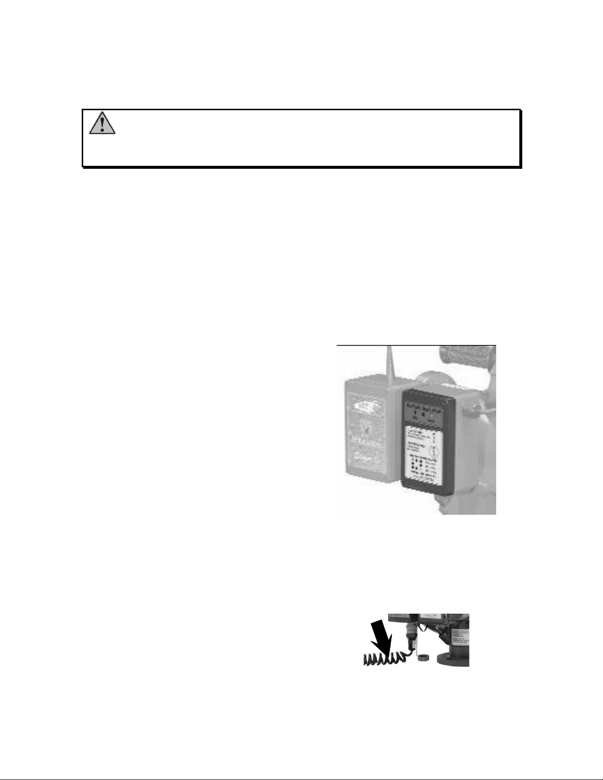
Monitor Settings
Switch 1 2 3 4 5 6 7 8
A
B
A
B
Monitor Location
Monitor Security Code
D
S
5
D
S
2
B
A
D
S
1
S
W
4
S
W
1
D
S
4
P
2
D
S
3
P
3
D
S
6
P
1
P
4
S
W
2
S
W
3
Status LED
Red Programming
Button
Table 3
Remove the cover from the control module mounted on the monitor.
Record Security Settings
Figure 14
24263001 Receiver Layout
Locate the security code switches on the control module circuit board (see Figure 14).
Change the code using the switches A and B. Switch A position 1 is not used for security
code settings.
For convenient reference to the security code of the monitor; enter the code into Table 1
provided above.
Monitor Selector
SW4 (Figure 14) allows this board to be used in different product applications. In
order for it to properly operate the Stinger RF monitor, it must be set to 5. If it is
set to a value that is not yet programmed, the status indicator LED, DS5 (Figure
14), will blink rapidly until a valid setting is selected and power is cycled off and
back on. If SW4 is set to a valid setting but not position 5, unpredictable results
will occur.
Page 19

16
Caution: While reassembling the handheld remote, ensure that battery and
antenna leads do not become pinched.
Note: Do not set the security switches to either all “ON” or all “OFF.” These
are invalid settings and will not allow the transmitter to function. In the handheld
transmitter, this will be signaled by the power and low battery signals flashing slowly at
the same time.
Caution: Do not change the switch A position 1 on any transmitter. This
switch is used to set the priority setting of the transmitter and changing this switch may
remove override capabilities.
81282001 Handheld Transmitter Settings
Remove the battery cover from the handheld transmitter. Remove the four screws
holding the two halves of the cover together using a #1 size Pozidriv screwdriver (use
caution with a standard Phillips screwdriver as it may eventually strip the heads of the
screws).
Locate the security code switches on the transmitter circuit board (see Figure 15).
Change the switches to the settings from Table 3 (pg 15). One incorrect setting will
prevent the system from working.
Ensure the battery lead connector is securely fastened to the transmitter circuit board.
Close the cover halves and replace the screws. Do not exceed 6 in-lbs of torque. The
screws should just be snug, do not over tighten the screws, or the plastic enclosure could
strip.
Figure 15
Transmitter Security Settings
Page 20

17
81327111 and 81353101 Panel Mount and OEM Transmitters
Disconnect the power connector to the panel-mounted transmitter at the back of the
panel.
Open the back cover of the transmitter after loosening the screws.
Remove the red and black power leads from the power conversion board and place the
cover to the side.
Locate the security code switches on the transmitter circuit board (see Figure 15).
Change the switches to the settings from Table 3 (pg 15). One incorrect setting will
prevent the system from working.
Reconnect the power leads. The Red lead is attached to the Positive (+) terminal; the
black lead is attached to the Negative (-) terminal.
Close the transmitter cover and replace the screws.
Reconnect the power connector.
Keep this Installation Manual in a secure place so the settings can be retrieved if
needed.
Page 21

18
(b) Lower the monitor down onto deck mount outlet
and push down evenly so that the latch pins pass
over the swivel ring. (The monitor should now
be resting on top of the swivel ring.)
(c) Confirm correct latch pin positions by checking
the visual indicators in the latch pin caps (Figure
16).
(d) Connect power/charging harness to bottom of
control enclosure.
(e) Charge the monitor. Increase the pressure until
the desired flow is reached.
Figure 16
Latch Pin Indicators
a) Shut down the water flow.
b) Disconnect the power/charging
cable by rotating connector nut
approximately ¼ turn.
c) Pull the twist release lock pin
up, and hold it. Twist the handle
and hold it to keep the latch pins
in the released position (see
Figure 17). The twist release lock
pin should now be released.
d) Support the nozzle and lift the
unit straight up off the truck
mount.
Figure 17
Twist Handle and Lock Pin
VI. OPERATION
A. Deck Gun Mode
1. Attachment and Operation
(a) Install the monitor by supporting the nozzle and holding the twist handle
on the upper monitor assembly. Align the inlet end of the monitor with
the outlet of the 8298 RF.
2. Monitor Removal from base
e) Release the twist handle, allowing the latch pins and the twist release lock
pin to return to their original position.
When the monitor is stored on the top mount adapter, the left-right pinion gear will be
engaged with the ring gear to prevent it from spinning on the swivel joint while the
apparatus is in motion. It is recommended that only the Elkhart Model 282A stream
Page 22

19
shaper be used with this monitor. The short length of the 282-A helps to minimize
stress on the discharge elbow gearing.
When the 8297 RF monitor is installed on a fire apparatus used in cold climates, a
drain valve should be provided in the riser pipe that supplies the monitor. The riser
should be drained immediately after each use during cold weather to prevent freezing
and possible damage to the monitor and piping. The discharge portion of the monitor
can be drained by simply lowering the discharge elbow below horizontal and allowing
the water to drain through the nozzle.
To reduce possibility of damage to the monitor by contact with overhead doors,
branches, etc, the nozzle discharge should be kept at the lowest possible angle.
B. Portable Monitor Mode
Carrying the upper monitor assembly on the truck mount adapter allows for its use as a
deck gun while the portable base and hose line(s) are being deployed. Determine the
portable base location (keeping in mind the need for a substantial stationary object to
which the safety strap can be attached that is in line with the intended stream
direction). Remember that the nozzle reaction force can be as high as 900 lbs.
1. Prepare the portable base for use by simply rotating each of the four folding
legs into its locked position, starting with the two rearmost legs. It is very
important that the legs be in the locked position prior to initiating water flow.
2. Anchor the portable base with
the safety strap (see Figure 18).
The safety strap should be
attached to the portable base at
the carrying handle support post
on the front leg bracket and
secured around a substantial
stationary object. The stationary
object, such as a stake, fence
post, etc., should be positioned
between the Stinger RF® monitor
and the intended target. The leg
bracket of the portable base
should point directly at the
stationary object and the intended
target. The monitor should never
3. Attach the hose(s) to the portable base. To minimize the possibility of the
charged hose lines moving the monitor, the supply hose should be kept
straight in line with its respective inlet port for a distance of at least ten feet.
4. Disconnect the power/charging cable by rotating connector nut approximately
¼ turn. Remove the upper monitor and nozzle assembly from the deck mount
be used with any slack in the
safety strap. If no suitable object
is available, the Elkhart
81460001 anchor kit must be
used.
Figure 18
Anchored Portable Base
Page 23

20
5. Confirm correct latch pin engagement by checking visual indicator cut outs in
6. Aim the monitor nozzle towards the intended target. The monitor discharge
7. Charge the hose lines slowly to prevent water hammer.
8. Operate the monitor as described in section VI.A.1, deck gun operation. (See
9. To lower the discharge below 30 degrees, simultaneously press and hold the
and attach it to the portable base. Attach the upper monitor assembly to the
portable base using the same technique used to attach it to the deck mount
adapter (see section VI.A.1).
latch pin caps (See Figure 16).
should not be turned more than 45 degrees to either side of the front leg
bracket.
Warning below).
“down” button and the “aux 2” button on the transmitter. Once the desired
position is attained, release the down button. The aux 2 button must be
continually depressed in order to sustain this position. If the aux 2 button is
released, the monitor will automatically return to the safe 30-degree elevation
position. As soon as the nozzle elevation is raised above 30 degrees the
up/down electronic stop will re-engage itself and need to be over-ridden again
to go below 30 degrees elevation.
Warning:
Use extreme caution when lowering the discharge elbow below the angle allowed by the
up/down electronic stop when flowing the Stinger RF® in portable mode. If the discharge
is lowered below the electronic stop, the nozzle reaction force may cause the monitor and
hose lines to slide. If the discharge is lowered below horizontal, the nozzle reaction force
will cause the monitor and hose lines to become airborne. Serious injury or death could
occur if these warnings are not followed.
C. Normal Operation
The 8297 RF Monitor uses the standard Left/Right, Up/Down, and Fog/Stream
commands to provide stream direction and pattern adjustments.
To move the monitor left or right, press and hold the left or right button until the monitor
discharge is in the correct position or a programmed limit is reached. To move the
monitor “up” or “down,” press and hold the up or down button until the monitor is in the
correct position or the electronic stop is reached. To adjust the stream pattern, press and
hold the fog or stream button until the desired stream pattern is reached. Elkhart electric
nozzles have a unique ball screw drive which when it reaches the extents of travel will
continue spinning until the button is released.
Page 24

21
Any combination of left, right, up, or down can be used to achieve motion in both
horizontal and vertical directions simultaneously. If the left and right buttons are pressed
at the same time, the monitor will stop all motion. To resume motion, release both
buttons and repress the desired direction button. This is also true for the up/down and
fog/stream commands.
The handheld remote transmitter has a power saving feature that turns the transmitter
power off if no signal is sent for 5 minutes. Press and hold the “ON/OFF” button until
the Power LED illuminates to reactivate the transmitter. The “Low Battery” LED will
flash slowly when the battery voltage drops below a predetermined level. When the low
battery LED flashes rapidly, the batteries are nearly discharged and should be replaced
immediately.
D. Oscillation Function
The 8297 RF monitor has an automatic left/right oscillation function, which can be used
to provide continuous exposure protection or hazard mitigation with no operator input.
The oscillation limits are set using the handheld or truck mount transmitters. To initiate
oscillation:
1. Position the monitor at either the left or the right limit of oscillation.
2. Press and hold the oscillate button.
3. Move the monitor to the other limit of oscillation. Release the direction button
4. Release the oscillate button.
5. Press and release the oscillate button to activate the oscillation function.
The monitor will oscillate between the limits until the oscillation button is pressed again.
Pressing the left or right button on one of the controls will also stop the oscillation.
For safety reasons, once oscillation has stopped the oscillation limits need to be
reprogrammed before it can be re-engaged. The nozzle fog, stream, and discharge
elevation functions can be operated while the monitor is oscillating.
E. Manual Override
The monitor left-right and up-down motion can be controlled manually in the event of
motor failure or loss of electrical power.
Up-Down
Push down on ball knob on crank handle
while turning CCW to raise nozzle, or CW
to lower nozzle. See Figure 19. Note that
manual override crank handle is normally
disengaged and will not rotate with normal
control up-down motion of the nozzle. This
is an important safety feature to prevent
hand or finger injuries.
Figure 19
Up-Down Manual Override
Page 25

22
Warning:
When up-down manual override is used, it is possible to position the nozzle elevation
below the electronic safety limit of 30 above horizontal. Use extreme caution to
prevent sliding of monitor when using manual override control.
Left-Right
The left-right manual override is controlled by a pushbutton located on top of the
left-right drive gearcase on the right side of the monitor. See Figure 20. To
override the motor drive mechanism, push and hold this button down while using
the other hand to rotate the monitor upper portion and nozzle to the desired
position.
Figure 20
Left-Right Manual Override
Caution: With the drive mechanism disengaged, there is no monitor left-right
rotation lock. It may be possible for the stream position to drift due to vibration.
Maintain close watch over stream position.
When motor is again actuated, the transmitter left-right drive will automatically reengage. This may take a few seconds of motor travel.
F. Power Switch
The power switch is used to control power to the monitor. If shore power is not available
and the power switch is in the OFF position, this will remove power form all circuits
inside the monitor. There will be no display indicators of any kind. If the switch is in the
ON position, the monitor will operate in the portable mode as described in section VI
paragraph B.
If shore power is present, the monitor will operate as describe in section VI paragraph C
in either the ON or the OFF position.
Page 26

23
VII. MAINTENANCE
A. Preventive Maintenance Procedures for Stinger RF Upper Assembly
Preventive Maintenance
The complete monitor and control system should be inspected during each apparatus
check. Careful inspection for damage to the monitor or nozzle is especially important
after use in emergency operations.
Operate each function (left-right, up-down, stream-fog, stow) with each of the
transmitters.
Remove nozzle and check for debris lodged between the nozzle stem and body, or in the
stream shaper inlet. Remove debris.
During nozzle flow test, inspect monitor swivel joints for leaks.
With the water off, operate the stow function, looking for any possible obstructions and
check the final stow position.
Inspect all exposed wiring for signs of damage.
Note: Although a grease fitting is provided for the up-down gear case, routine
greasing should not be necessary. If the monitor is exposed to a high level of radiant
heat for a prolonged period, it may be possible for the factory grease to thin and run
out of the gear case. In such an event, fresh grease should be applied.
After Each Use:
Check for proper latch pin operation. To do this turn the upper unit upside down
and push each latch pin up into its respective hole. It should move smoothly,
easily, and far enough into its hole that no part of the pin is exposed in the large
bore. Using the twist release mechanism, make sure that the latch pins retract
fully into their holes and are not exposed in the large bore when the grip is twisted
to its limit. Release the twist grip and check to be sure the latch pins both return
to the fully latched position by checking the visual indication windows in the
latch pin caps (See Figure 16, Pg.18). With the twist release stop pin pulled, twist
and release the grip several times. The grip should turn smoothly when released.
Pull and release the twist release stop pin to make sure it is working freely. Pull
the twist release stop pin and rotate the twist handle to the fully released position.
Release the stop pin and then release the twist handle. The mechanism should
quickly and smoothly return to the fully latched position and the twist release stop
pin should reset to the locked position
The twist handle has nylon bushings, the cable guides are plastic lined, and the
latch pin caps and holes are hard coated and Teflon impregnated to provide years
of smooth operation without lubrication. Lubrication will attract dirt and possibly
cause the latch pin mechanism to hang up, creating a severe safety hazard.
Warning:
If any part of the latch pin mechanism hangs up or does not seem to work correctly, DO
NOT use the monitor. DO NOT lubricate any part of the latch pin mechanism. Contact
Elkhart Brass for further instructions.
Page 27

24
As Needed:
Check that the interior of the monitor inlet is clean. Flush out any dirt with clean
water. To assure ease of left/right rotation, periodically apply a light coating of
general-purpose petroleum grease to the U-Cup seal within the monitor inlet. Do
not remove the seal for lubrication.
Grease the worm gear as needed with general-purpose petroleum grease. Rotate
the manual override to raise the discharge to its highest elevation, apply grease to
the fitting located on the lower front of the unit. Fill it until grease appears at the
discharge elbow joint. Lower the discharge to the electronic stop limit and repeat
the grease procedure. Lower the discharge to its lowest position, and repeat the
grease procedure again. Raise the discharge until the electronic stop is reset.
Wipe off the excess grease. Clean the monitor with soap and water only. DO
NOT use any type of solvent, thinner, or similar product with this unit.
Replace the labels if they become illegible, lost, painted over, or removed.
B. Maintenance Procedures for Stinger RF® Bases
After Each Use:
Clean any dirt from the unit with mild soap and fresh water. DO NOT use any
type of solvent, thinner, or similar product with this unit. No lubricants should be
used on the portable bases. The aluminum parts are hard coated and Teflon
impregnated and need no lubrication.
Inspect the ring gear, looking for damaged or dirty teeth. Clean the teeth if
necessary.
Inspect the spring loaded ground spikes for damage and proper function. The
spike assembly parts should move in and out freely. Inspect the ground spikes.
The carbide tips should come to a sharp point. Replace the ground spike
assembly if the carbide tips are damaged. Replace the ground spike assembly by
removing the ground spike retainer from the leg. Turn the retainer counterclockwise with the correct size socket or wrench, and remove the spike assembly
and coil spring. Clean the leg socket. Place a small amount of Loctite #242 on
the male thread of the retainer before installation. Install the spring, new spike
assembly, and retainer. Tighten the retainer firmly.
Inspect each of the folding legs for correct operation of the lock pins and smooth
operation on their pivot screws. Check the leg lock pins by sliding them back and
forth in their bores using the yellow-capped pins on both sides of the leg near the
pivot point. The lock pins should slide smoothly in the leg bore and the coneshaped end should fit snugly into the tapered hole in the leg bracket. Retract the
lock pin and rotate the leg back and forth on the pivot screw. The leg should
rotate freely. If needed, flush the leg assembly with water while cycling the lock
pin and/or leg through its full range of motion until smooth operation is achieved.
Inspect the safety strap and snap hooks. Make sure that the spring-loaded closure
on the snap hooks pivots freely and returns to the locked position.
Page 28

25
As Needed:
Reference
Indication
Meaning
1
Light comes on for 1 second
when monitor stops
Motor has reached stall current and
performing normal shutdown
2
Blinks 6 times at 1 second rate
during startup
Visual indication that the controller is
initializing – normal operation
3
Blinks 2 times at 1 second rate
during startup then blinks at ¼
second rate continuously
SW4 (Figure 14) in wrong position –
must be in position 5 for proper Stinger
RF operation
4
Blinks at ½ second rate
Truck battery voltage <8 volts - light
will blink until power is lost or is
restored – early power fail (EPF)
indication
Replace any damaged parts including illegible labels. Part numbers can be found in
the exploded parts drawings at the end of this manual. Parts can be ordered from any
Elkhart Brass distributor, or directly from Elkhart Brass Mfg. Co. Inc. Please call 1800-346-0250 with any questions about this or any other Elkhart Brass product.
Understanding the Controller LEDs
LED Notations
DS1 (Figure 14) - Lights when either nozzle direction is engaged.
DS3 (Figure 14) – Lights when the UP or the DOWN button is depressed.
DS4 (Figure 14) – Lights with any left/right movement.
DS5 (Figure 14) – See Table 4
DS6 (Figure 14) – Lights when power is applied.
Table 4
DS5 Status Indicator LED (Indication VS. Meaning)
Handheld Transmitter
Battery Type
The 8297 RF handheld transmitter uses two AA alkaline batteries. The low battery light
will illuminate with approximately two hours of transmission time remaining before the
batteries are completely discharged. Due to the time-voltage characteristics of
rechargeable batteries, this time could be drastically reduced if rechargeable batteries are
used.
Replacing the Battery
The batteries can be replaced with any standard fresh AA alkaline batteries.
Turn the transmitter power off.
Remove two screws and the battery cover.
Remove the old AA batteries.
Insert the new AA alkaline batteries.
Replace the battery cover using the screws.
Page 29

26
VIII. MONITOR & STREAM SHAPER HYDRAULIC DATA
ΔP
S
= HF + ΔP
V
ΔP
S
= Total Static Pressure Drop
HF = Friction Loss
ΔP
V
= Velocity Pressure Loss
Interpreting Flow Data
The following graphs offer the pressure losses for the monitor (and other devices) in
terms of Total Static Pressure Drop. This Total Static Pressure Drop can be found by
measuring the difference between the static inlet pressure and the static outlet pressure.
The static pressure at either of these points can be found using a simple pressure gauge.
An illustration of this method can be seen below.
In mathematical terms, the Total Static Pressure Drop is the change in Velocity Pressure
plus Friction Loss. The change in Velocity Pressure results from the change in velocity
of water caused by the change in the cross section of a waterway. Friction Loss results
from the drag and sidewall interference of the water through a device. A simple equation
can be seen below.
In the firefighting industry, the terms Total Static Pressure Drop and Friction Loss tend to
be used interchangeably. However, these are significantly different measurements. This
misconception could ultimately lead to lower than anticipated performance from
equipment. When designing a system and determining performance, Total Static
Pressure Drop is the value that should always be used. The Friction Loss curve is also
supplied in order to make a comparison with competitor products that may only supply
Friction Loss curves. If there are any further questions regarding this matter, please
contact Elkhart Brass.
Page 30

27
Page 31

28
Page 32

ELKHART BRASS MFG. CO., INC.
P.O. Box 1127 · 1302 West Beardsley Ave.
Elkhart, Indiana 46515
E-mail: info@elkhartbrass.com
Website: www.elkhartbrass.com
(800) 346-0250
98308000 Rev. F
 Loading...