

Page 1
E
E
LLKKHHAARRTT
B
B
RRAASSSS
M
M
FFG
G
.
.
C
C
O
O
..,
,
I
I
NNC
C
..
1302 WEST BEARDSLEY AVENUE P.O. BOX 1127 ELKHART IN 46515 (574) 295-8330 FAX (574) 293-9914
Operating, Installation, and Maintenance Instructions
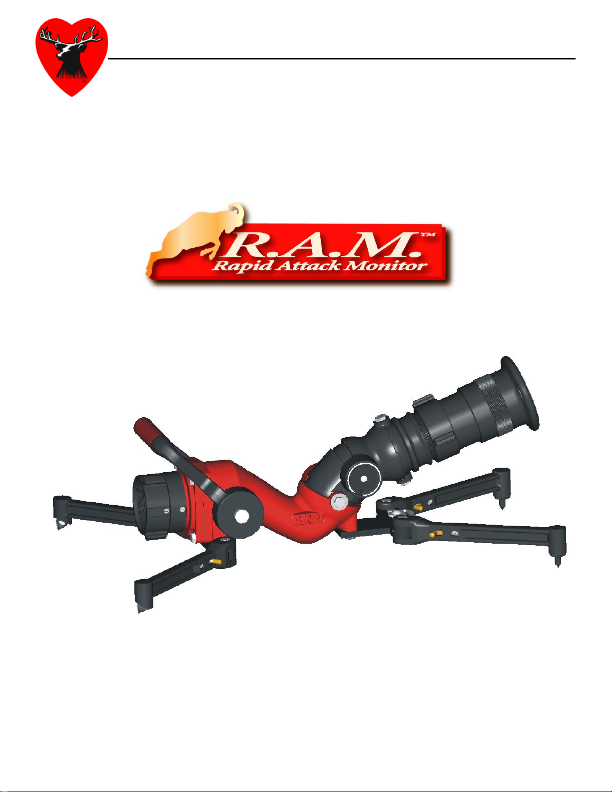
RAM Personal Portable Monitor
Catalog Number: 8296
P/N: 98293000 REV D
Page 2

RAM Physical Data:
Folded Length = 16.2” Deployed Length = 25.1”
Folded Width = 8.4” Deployed Width = 23.4”
Folded Height = 8.8” Deployed Height = 8.8”
Deployed Footprint = 433 sq. in.
Monitor Weight = 17.0 lbs Monitor Weight w/RAN = 21.5 lbs
Vertical Stream Path = 20degrees above horizontal minimum
63 degrees above horizontal maximum
*** patent pending safety system active between 20 and 35
degrees above horizontal
Horizontal Stream Path = +/- 20 degrees of monitor centerline
RAM Operating Data:
Max Pressure = 150 psi
Max Flow = 500 GPM
Monitor Tie Down = Integral Safety Strap Included
*** For safety purposes and to reduce the risk of injury, all
personal monitors require the use of a safety strap / chain
to secure the monitor to a fixed / stable base.
RAM Features:
Safety System (patent pending)
Counter Balance System (patent pending)
Integral Safety Strap with Pouch
Locking Valve Control / Carrying Handle
Hydro-Loc Valve Position Control Mechanism
4 Retractable Forged Legs
Carbide Ground Spikes (spring loaded front spikes)
Full Vaned Water-Way
Straight Stream / Fog Nozzle, Smooth Bore Nozzle, Stack Tips, Mini Stream
Shaper Accessories
Truck Mounting Bracket
Page 3

Table of Contents
Product Safety Information ………………………………………………………. i, ii
Section 1 – RAM Product Description ………………………………………….... 2-3
Leg Pivot and Lock Pin ……………………………………………………2
Forged Aluminum Leg ……………………………………………………. 2
Carbide Tipped Ground Spike ……………………………………………. 2
Safety Strap ……………………………………………………………….. 2
Carry / Valve Control Handle .....................................………………….... 2
Handle Lock Pin ………………………………………………………..… 2
Counter Balance System ………………………………………………..… 2
Safety System …………………………………………………………….. 3
Hydro-Loc Valve Position Control ……………………………………….. 3
Fully Vaned Waterway …………………………………………………… 3
Inlet / Outlet Configuration ………………………………………………. 3
Section 2 – RAM Accessories ……………………………………………………. 3-4
RAN Straight Stream / Fog Nozzle ………………………………………. 3
1-3/8” Discharge Smooth Bore Nozzle ……………………………………3
Stack Tips ………………………………………………………………….4
Mini Stream Shaper ………………………………………………………. 4
Truck Mounting Bracket ………………………………………………….. 4
Section 3 – RAM Operation ……………………………………………….. 4-6
Deployment of the RAM …………………………………………………. 4-5
Flowing Water with the RAM ……………………………………………. 5-6
Storage of the RAM ………………………………………………………. 6
Section 4 – Maintenance of the RAM …………………………………………….. 6-7
Maintenance After Every Use …………………………………………….. 6-7
Maintenance Recommended Every Six Months ………………………….. 7
Section 5 – Mounting Bracket Detail Drawing and Installation Template ……….. 7-8
Section 6 – Friction Loss and Effective Reach Charts ………………………….... 9
Page 4

List of Figures
Figure 1 – RAM Left Side View …………………………………………..1
Figure 2 – RAM Right Side View ………………………………………....1
Figure 3 – RAN Straight Stream / Fog Nozzle …………………………… 3
Figure 4 – 1-3/8” Discharge Smooth Bore Nozzle ……………………….. 3
Figure 5 – Stack Tips ……………………………………………………... 4
Figure 6 – Mini Stream Shaper …………………………………………… 4
Figure 7 – Truck Mounting Bracket …………………………………….... 4
Figure 8 – Truck Mounting Bracket Drawing ……………………………. 7
Figure 9 – Truck Mounting Bracket Installation Template ………………. 8
Figure 10 – Friction Loss Chart …………………………………………... 9
Figure 11 – Effective Reach Chart ………………………………………...9
Page 5

1. leg pivot and lock pin
1
1
2
2
3
3
4
5
6 7 8
9
7
10
12
13
2. forged aluminum leg
3. carbide tipped ground spike
4. safety strap
5. carry / valve control handle
6. handle lock pin
7. counter balance mechanism
8. upper waterway pivot point
9. lower waterway pivot point
10. hydro-loc valve position control mechanism
11. fully vaned waterway
12. 2.5” NH free swivel inlet
13. 2.5” NH outlet
Page 1
Page 6

11
Section 1 – RAM Product Description
The RAM (Rapid Attack Monitor) is designed to provide the fire-fighter / rescue
personnel an efficient and distinct advantage in the application of water or foam at an
incident site. This product is a light weight aluminum device designed to a single
operator the ability to deliver 500GPM of water as necessary. The monitor is self
contained and can be mounted in a pre-connect condition utilizing the truck mounting
bracket such that quick deployment can be achieved for effective initial attack.
Leg Pivot and Lock Pin
The forged aluminum legs have integral lock pins that are spring loaded for
proper engagement when the legs are fully deployed. This provides a stable /
reliable base for the monitor in use.
Forged Aluminum Legs
Forged aluminum legs provide superior strength over cast leg configurations.
Carbide Tipped Ground Spikes
The carbide tipped ground spikes provide secure engagement of the legs across a
wide variety of soft and hard surfaces. The front spikes are spring loaded to assist
engagement on uneven surfaces. Severe uneven surfaces where contact of all
four legs can not be achieved simultaneously should be avoided. The rear spikes
are angled to provide greater contact in the direction opposing the reaction forces
generated by the water flow.
Safety Strap
The monitor is supplied with a length adjustable braided nylon safety strap for use
in securing the device to a fixed stable base prior to any use. The metal clip at the
end of the safety strap makes attachment of the strap to a pole, tree, guard rail or
other such fixture quick and easy. A pouch is provided to keep the strap
organized during transport of the monitor.
Carry / Valve Control Handle
The large comfortable handle acts both as a carry handle in the fully closed and
locked position and as a valve control handle to open / close the waterway.
Handle Lock Pin
A spring loaded lock pin with a large pull knob is provided to insure the carry /
valve control handle remains in the closed position during any time water flow is
not desired.
Counter Balance Mechanism
The counter balance mechanism keeps the nozzle position from drifting
downward due to the weight of the nozzle / outlet devices. This mechanism must
Page 2
Page 7

not be altered in any way and repair should only be conducted by Elkhart Brass
personnel. The Counter Balance Mechanism is patent pending.
Safety System
The unique flow path generated by the lower and upper waterway pivot points
provides two specific advantages. (1) The two pivot points provide a smoother
waterway transition through its most extreme bends which improves stream
quality. (2) The offset configuration of the two pivot points create a condition
where the reaction force of the water acting on the upper pivot point, if sufficient,
will cause the nozzle to rotate upward about the lower pivot point. This produces
a self correcting increase in nozzle angle to protect against possibly dangerous
unmanned use of the monitor at nozzle angles less than 35 degrees above
horizontal. The hydraulic effect of the Safety System is active at approximately
350 GPM. The Safety System is patent pending.
Hydro-Loc Valve Position Control
The RAM shut off valve utilizes the Elkhart Brass Hydro-Loc mechanism to hold
the valve in a throttled position if desired.
Fully Vaned Waterway
The waterway of the body has a full cast vane to improve water flow and
discharge stream quality.
Inlet / Outlet Configuration
The RAM is manufactured standard with a 2.5” NH thread inlet and a 2.5” NH
thread outlet. Special thread configurations can be addressed upon request.
Section 2 – RAM Accessories
RAN Straight Stream / Fog Nozzle
The RAN (Rapid Attack Nozzle) is a purpose built nozzle
designed for use with the RAM. RAN is lightweight and
utilizes very few components to deliver water in both
straight stream and fog pattern. Significant to the stream
quality of the RAN is its integral stream shaper. The RAN
delivers 500 GPM at 75 psi and 400 GPM at 50 psi. The
RAN is manufactured standard with 2.5” NH threaded
swivel. Special thread configurations can be
addressed upon request.
1-3/8” Discharge Smooth Bore Nozzle
Elkhart Brass offers a 1-3/8” discharge smooth bore
nozzle which will provide 500 GPM at 75psi. The
nozzle is manufactured standard with 2.5” NH
Page 3
Page 8

thread. Special thread configurations can be
addressed upon request.
Stack Tips
Elkhart Brass offers stack tips in two combinations.
(1) 1-1/2”, 1-1/4”, 1” discharges
(2) 1-3/8”, 1-1/4”, 1-1/8” discharges
The stack tips are manufactured standard with NH
threads, 2.5” on the stack inlet. Special thread
configurations can be addressed upon request.
Mini Stream Shaper
Elkhart Brass offers a mini stream shaper for use
with the smooth bore nozzle and stack tips for
improved discharge stream quality. The mini
stream shaper is manufactured standard with 2.5”
NH inlet and outlet. Special thread configurations
can be addressed upon request.
Truck Mounting Bracket
Elkhart Brass offers a light weight truck mounting
bracket designed to hold the RAM in place during
storage and truck transport. The bracket can be
mounted in either the horizontal or vertical
positions with strap orientation interchangeable
between left and right latching.
Section 3 – RAM Operation
The RAM is an easy to use device designed for single fire fighter deployment.
However, any device capable of flowing 500 GPM can become very dangerous if not
used properly. All personnel who use this device should be thoroughly familiar with its
operation. The following outlines proper use of this device.
Deployment of the RAM
The following steps outline proper deployment of the RAM.
1) Retrieve the RAM from the mounting bracket or its storage area.
2) Carry the RAM to the preferred location for deployment. Make sure to select a
surface that is stable and level in proximity of a fixed object (tree, guard rail,
post, etc) that can be used to secure the monitor.
3) Extend each of the four legs making sure that the lock pin for each leg is
securely in place.
Page 4
Page 9

4) Place the RAM on the ground and position it so that it is in line with the target
at which water is to be delivered. Take care to insure that all four carbide tipped
ground spikes are securely in contact with the ground.
5) Secure the RAM to a fixed object (tree, guard rail, post, etc) using the attached
safety strap and take up any slack in the strap.
Important: All personal portable monitors must be secured to a stable fixed
base to prevent uncontrolled movement during use – the monitor must be tied down
6) If the RAM has not been utilized in a pre-connect condition, securely attach a
hose line to the monitor at this point.
Flowing Water with the RAM
The following steps outline the proper procedure for flowing water with the
RAM.
1) Verify that there are no kinks in the hose line connected to the RAM. Also
make sure that there is at least 20 feet of hose feeding into the RAM in direct
line of the RAM’s flow path for best quality of stream.
2) Indicate to the pump operator to charge the line to the proper pressure / flow
requirements.
Important: Never exceed 150 psi.
Important: Never exceed 500 GPM
Important: It will be necessary to field test the RAM prior to initial use and
create a flow chart for pump operation such that the appropriate pressure / flow
conditions will be met at the RAM.
3) Pull the lock pin on the valve control handle and slowly open the valve to its
full open position.
4) Keeping moderate weight on the RAM, move the nozzle to direct the discharge
stream of water to the desired target.
Important: Never straddle the hose line feeding the RAM. This can create a
dangerous situation for the operator if there is any unwanted movement of the monitor,
hose, etc. A knee or the hand opposite the hand being used to direct the stream of water
Page 5
Page 10

can be conveniently placed on hose just behind the inlet connection for added monitor
support.
5) If it becomes necessary to move the monitor to a new location. Slowly close
the valve control handle and verify that the lock pin is latched. The monitor can
now be repositioned while the hose line is charged.
6) If the RAM is repositioned, verify that the criteria outlined in the “Deployment
of the RAM section” have been satisfied.
7) When use of the RAM is complete. Slowly close the valve control handle and
verify that the lock pin is latched.
8) Indicate to the pump operator to close the water feed to the hose line that is
attached to the RAM. Any residual hose line pressure can be released by slowly
opening and re-closing the valve control handle.
Storage of the RAM
The following steps outline the proper procedure for returning the RAM to
storage.
1) Remove the safety strap from the fixed object it had been secured to and place
the strap back into the attached pouch.
2) Fold the legs of the RAM by pulling outward on the lock pin cross lever to
disengage it. The front legs are folded towards the back first and the rear legs
are then folded forward.
3) If the RAM is not to be stored in a pre-connect condition, disconnect the hose
line from the monitor inlet.
4) Return the RAM to its mounting bracket or storage area and secure for
transportation.
Section 4 – Maintenance of the RAM
The following section outlines the necessary maintenance procedures for the RAM.
Adherence to these recommendations will keep the RAM operational and reduce the
possibility of field difficulty or failure.
Maintenance After Each Use
Verify that the carbide tipped ground spike on each of the four legs is sharp and
undamaged. If any tip has a flat larger than 1/16”, replace the carbide tip. If any
of the tips show signs of damage, replace the carbide tip ground spike before the
next use.
Verify that the lock pin mechanism for each leg is in good condition. Examine
the lock pin end and the leg bracket slot that the lock pin connects for damage. If
any damage is noticed, replace that specific leg assembly / bracket as needed.
Examine the spring to insure it is operating properly. If any springs are not
Page 6
Page 11

operating properly, replace that specific leg assembly. If necessary a light weight
water repelling lubricant can be applied to the lock pin / spring mechanism in the
legs.
Inspect the safety strap for visible damage. The strap should inspected for fraying
and the D-Clip and Length Adjustment Ring should be inspected for physical
damage. If any of the components are damaged they need to be replaced before
the next use.
Verify that the lock pin on the valve control handle is operating properly. If any
damage or operational issue is detected, repair as necessary. If needed, a light
weight water repelling lubricant can be applied to the valve control lock pin /
spring mechanism.
Operate the valve control handle from full closed to full open in order to insure
the shut off ball is working properly and lubricated. The shut off ball can be
observed from the inlet of the RAM.
Visually inspect the RAM for any noticeable damage. Repair as needed.
Important: If there is a question regarding any necessary repair or damage
issue, contact Elkhart Brass for assistance.
Maintenance Recommended Every Six Months
The valve ball should be inspected for physical damage and lubricated with a light
grease.
The RAM internal passage ways should be inspected for possible damage caused
by foreign objects that have carried by the water through the monitor. If damage
affecting the integrity of the monitor is noticed, contact Elkhart Brass for
assistance.
SECTION 5 – Mounting Bracket
Detail Drawing and Installation
Template
The mounting bracket is designed to accommodate
mounting locations that are close to physical
obstructions on one or the other side of the bracket such
as a truck wall or other surface mounted device on a
Page 7
Page 12

truck. The attachment strap and clip ring can be removed and reversed to place the
hook mechanism on the opposite side if a physical interference exists.
Page 8
Page 13

Page 9
Page 14

RAM PRESSURE DROP
0
2
4
6
8
10
12
14
16
0 100 200 300 400 500 600 700
FLOW (GPM)
PRESSURE DROP (PSI)
RAM REACH CHART
With RAN Nozzle
0
50
100
150
200
250
0 100 200 300 400 500 600
Flow (GPM)
Reach (ft.)
SECTION 6 – Friction Loss and Effective Reach Charts
Page 10
Page 15

ELKHART BRASS MFG. CO., INC.
P.O. Box 1127 · 1302 West Beardsley Ave.
Elkhart, Indiana 46515
E-mail: info@elkhartbrass.com
Website: www.elkhartbrass.com
(800) 346-0250
98293000 Rev. D
 Loading...