

Page 1
1
1302 WEST BEARDSLEY AVE • ELKHART, IN 46514 • 574-295-8330 • 800-346-0250 98370000 REV B
© 2012 ELKHART BRASS MFG. CO., INC. • WWW.ELKHARTBRASS.COM
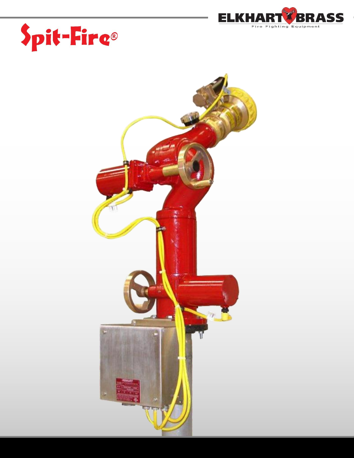
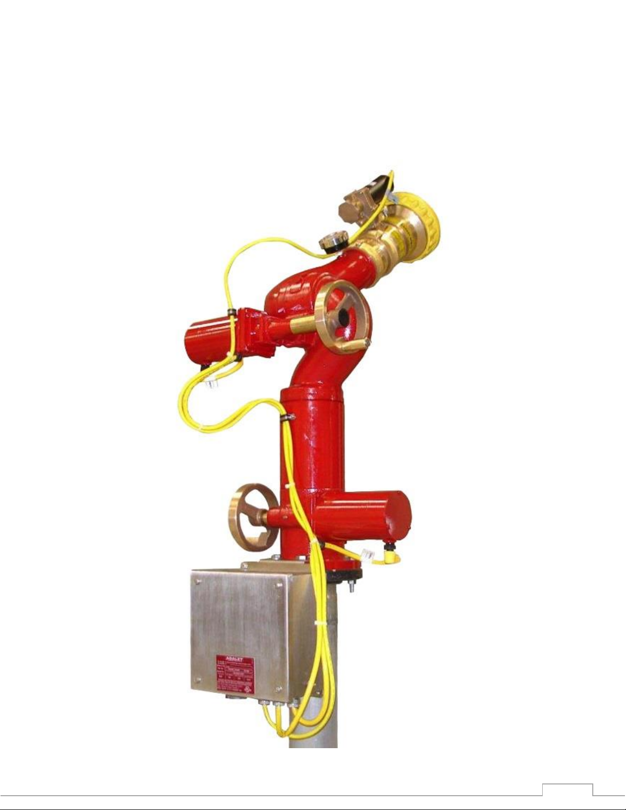
08394059 Monitor
Installation, Operation, & Maintenance Instructions
FOR ATEX APPLICATIONS
Page 2

2
TABLE OF CONTENTS
PRODUCT SAFETY INFORMATION 3
MONITOR CALLOUT DRAWING 4
OVERVIEW 5
INSTALLATION INSTRUCTIONS 6
OPERATING INSTRUCTIONS 9
MAINTENANCE 9
SPECIFICATIONS 10
MONITOR HYDRAULIC DATA 10
DIMENSIONAL DRAWINGS 11
WIRING 12
NOTES 13
Page 3
3
PRODUCT SAFETY INFORMATION
All personnel who may be expected to operate this equipment must be thoroughly trained in its safe
Important: Before installing and operating this equipment, read this manual
thoroughly. Proper installation is essential to safe operation.
Warning: Do not attempt to disconnect or work on any electrical equipment in this
system unless power is removed or the area is known to be non-hazardous.
and proper use.
Before flowing water from this device, check that all personnel (fire service and civilian) are clear of
the stream path. Also confirm stream direction will not cause avoidable property damage.
Become thoroughly familiar with the hydraulic characteristics of this equipment, as well as the
pumping system used to supply it.
Whenever possible, this equipment should be operated from remote location to avoid exposing
personnel to dangerous fire conditions.
Always open and close valves slowly to avoid water hammer.
After each use, and on a scheduled basis, inspect equipment per instructions in the maintenance
section.
Keep fingers and hands clear of moving parts.
Disconnect power before servicing and electric valve or electric valve controller.
Any modifications to the electrical will destroy the IP-66 rating and void warranty coverage of the
enclosure and all components within.
All equipment must be installed in accordance with ATEX requirements (EN/IEC 60079-14) as
appropriate and in areas where equipment classification is suitable.
MONITOR INFORMATION:
SERIAL NUMBERS:__________________________________________________________________________
DETAILS:
__________________________________________________________________________________________
__________________________________________________________________________________________
__________________________________________________________________________________________
__________________________________________________________________________________________
__________________________________________________________________________________________
Page 4
4
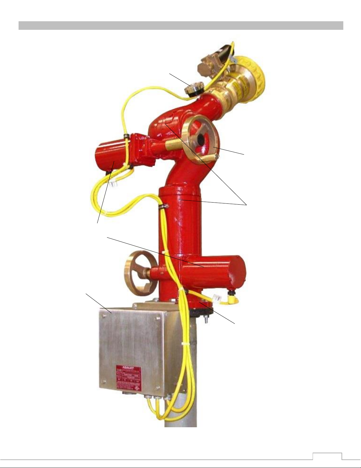
MONITOR CALLOUT
Figure 1: Monitor Callout Drawing
Pressure Gauge
Constant Torque /
Constant Current Motors
Manual Override
Double Race Bearings
Junction Box
4”-150# ANSI Flange
Page 5
5
OVERVIEW
Spit-Fire® Monitor Featuers:
Warning: DO NOT TAKE COVER OFF OR DISASSEMBLE MONITOR MOTORS. If
cover is/has been removed, the warranty is void and the service life of the motor is
significantly reduced.
Construction: All brass with vaned 4” waterway
Mounting Flange: 4” 150# flat-face ANSI flange raised face flange available as option
Discharge: 3½” NHT male outlet
Stream Shaper: #284-B brass shaper included
Flow: 2000 GPM max flow @ 200 PSI max working pressure
7600 LPM @ 14 BAR
Motors: 120 VAC NEMA 4 rated synchronous motors (non-arcing)
o Constant torque and current output in start, running, and stall
o ATEX Certified to II 3 G c (Ex nA II T4)
o Will not cause damage or increase in current when motor is stalled
o Instantaneous start, stop, and reverse
o Residual (Power Off) torque is always present
o Long life and exceptional reliability
o 120 VAC, 50/60 Hz., 1 Phase, 0.80 Amp current per motor
Junction Box: NEMA #4X (IP-66) water tight, corrosion resistant ATEX certified (Ex eII T6),
enclosure with terminals for hazardous locations. Stainless Steel motor
cable junction box with bracket to attach to monitor, flange base included.
Range of Motion: Monitor stops are factory set at 346° horizontal (+173° to -173° from front
center), and 135° vertical (+90° to -45°)
Rate of Horizontal Motion: 0.139 Sec/°
Manual Override: Hand wheels provided for vertical and horizontal movements. Hand wheel
will not rotate when monitor is operated electrically.
CE ATEX Certified (Group II, Category 3) II 3 G c T3
Page 6

6
INSTALLATION INSTRUCTIONS
Monitor Installation
Warning: When installing the monitor on a raised face companion flange or wafer
type valve, it is critical that the bolts be tightened uniformly to prevent misalignment
of the monitor relative to the flange or valve. If the monitor becomes misaligned, the
base flange will fracture and fail when the bolts on the “high” side are tightened.
1. Attach companion flange to water supply pipe so that the bolt pattern will allow the monitor to be
installed with the “straight ahead/neutral” position (see Dimensional Drawing section) properly
aligned. Alignment is correct when the “straight ahead/neutral” direction is centered between
adjacent flange bolt holes.
2. Install the monitor assembly on the water supply flange so that it matches up to a 4”-150# flat
faced ANSI flange on the inlet of the monitor, with a flange gasket between the flanges. Install
motor cable junction box by aligning the two-holed bracket with the flange mounting holes on the
rear of the monitor. Secure the inlet flange with eight (8) 5/8”-11 UNC Grade 5 hex head bolts.
Torque bolts to 60-70 ft-lbs.
3. Standpipe must be structurally strong enough to withstand reaction forces of the nozzle when
discharging a straight stream at 90° of the standpipe tower. The formula for calculating nozzle
reaction is: [REACTION FORCE = 0.0505 x GPM x √ PSI]
4. The inlet pressure at the base of the monitor must be high enough to allow for pressure loss
through the monitor. To accomplish this, use the pressure loss for GPM flowing and add to nozzle
pressure. See Monitor Hydraulic Data section for pressure loss chart.
Page 7
7
Monitor Cable Routing
Figure 2: Monitor Cable Routing
1. Route cables as shown in Figure 2 below, so they will follow the vertical and horizontal movement
of the monitor. Make sure that the wire loops for horizontal and vertical movement is great
enough to eliminate any stretching of cables throughout the full movement of the monitor.
2. Wire tie cables together as shown in Figure 2 below. This will eliminate the cables from tangling.
3. Wire tie the nozzle cable to pressure gauge, allowing a long enough loop so vertical movement of
monitor will go to the full down position without stretching the cable.
Page 8

8
Monitor Safety Boot and Clamp Installation
Figure 3a: Monitor Motor Boots
Figure 3b: Nozzle Motor Boots
All Motor Cable Connections are provided with clamped safety boots. These boots must not be
removed when monitor motor control panel is energized and area is hazardous.
1. Install corrugated black plastic boot on cable connector as shown so split lines up with cable.
2. Install clamp around top of boot and connector swivel.
3. Tighten clamp down around swivel and boot.
Page 9

9
OPERATING INSTRUCTIONS
One Monitor Control
MAINTENANCE
Warning: Do not attempt to disconnect or work on any electrical equipment in this
system unless power is removed or the area is known to be non-hazardous.
This operator control panel has one set of switches and pilot lights to operate one monitor.
Monitor Functions – UP, DOWN, LEFT, & RIGHT are operated with spring return joysticks. This is
accomplished by using the proper selector/pushbutton joystick to move the monitor the direction
desired. When joystick is released, it will return to original (off) position, and monitor movement
will stop.
Monitor Manual Control
Vertical Manual Override – Push hand wheel inward to engage override. While holding the
hand wheel in, rotating it clockwise will raise the nozzle, and rotating it counter-clockwise will
lower the nozzle.
Horizontal Manual Override – Push hand wheel inward to engage override. While holding hand
wheel in, rotating it clockwise will move the monitor right, and rotating it counter-clockwise will
move the monitor left.
When monitor operation is completed, move vertical movement to full down position to allow water to
drain from nozzle. When water is drained from nozzle, move monitor to park position.
Monthly Inspection & Maintenance
Cycle all monitor functions (LEFT, RIGHT, UP, DOWN) to insure the complete system is fully
functional.
Six-Month Inspection & Maintenance
Grease monitor ball races through grease fittings located at each swivel joint. Recommended
grease for Industrial Spit-Fire® monitors is MOBILITH SHC – 100, High Performance Synthetic
Grease. Temperature range: -40°F (-26°C) to 400°F (250°C) or equal. Greasing procedures are
as follows:
o Apply approx. 5-7 pumps of grease in the lower grease fitting, and 2-3 pumps in the
upper grease fitting
Check motor control cables for water and connectors for damage.
Check motor cables for binding through full movement of monitor.
Check all painted surfaces for chips or scratches, and repaint as required.
Visually check all electrical equipment.
Page 10

10
SPECIFICATIONS
General Specs
MONITOR HYDRAULIC DATA
Figure 4: Monitor Friction Loss Chart
8394053 “ SPI TFI RE” M on it or
Pressure Drop Data
0
5
10
15
20
25
30
35
40
45
50
55
Pressure Drop (PSI )
200
400
600
800
1000
1200
1400
1600
1800
2000
Flow (GPM)
Input Power 120/240 VAC (50/60Hz.) 1 Phase
Electrical Load 2 AMPS Per Monitor / 0.80 AMPS Per Motor
Monitor Dimensions 23” dia. x 52” h
Monitor Weight Appox. 300 lbs.
Operating Temperature Range -40°C to +85°C
ATEX Product Marking
II 3 G c T3
Page 11

11
DIMENSIONAL DRAWING
Figure 5: Monitor Dimensional Drawing
Page 12

12
WIRING
Figure 6: Monitor Cable Wiring to Junction Box Terminals
Page 13

13
NOTES
__________________________________________________________________________________________
__________________________________________________________________________________________
__________________________________________________________________________________________
__________________________________________________________________________________________
__________________________________________________________________________________________
__________________________________________________________________________________________
__________________________________________________________________________________________
__________________________________________________________________________________________
__________________________________________________________________________________________
__________________________________________________________________________________________
__________________________________________________________________________________________
__________________________________________________________________________________________
__________________________________________________________________________________________
__________________________________________________________________________________________
__________________________________________________________________________________________
__________________________________________________________________________________________
__________________________________________________________________________________________
__________________________________________________________________________________________
__________________________________________________________________________________________
__________________________________________________________________________________________
__________________________________________________________________________________________
__________________________________________________________________________________________
__________________________________________________________________________________________
__________________________________________________________________________________________
__________________________________________________________________________________________
__________________________________________________________________________________________
__________________________________________________________________________________________
__________________________________________________________________________________________
__________________________________________________________________________________________
__________________________________________________________________________________________
__________________________________________________________________________________________
__________________________________________________________________________________________
__________________________________________________________________________________________
__________________________________________________________________________________________
__________________________________________________________________________________________
__________________________________________________________________________________________
__________________________________________________________________________________________
__________________________________________________________________________________________
__________________________________________________________________________________________
__________________________________________________________________________________________
__________________________________________________________________________________________
__________________________________________________________________________________________
__________________________________________________________________________________________
__________________________________________________________________________________________
__________________________________________________________________________________________
__________________________________________________________________________________________
__________________________________________________________________________________________
__________________________________________________________________________________________
__________________________________________________________________________________
Page 14

ELKHART BRASS
1302 WEST BEARDSLEY AVE
P.O. BOX 1127
ELKHART, IN 46514
PHONE: 574-295-8330 • 800-346-0250
FAX: 574-293-9914
WWW.ELKHARTBRASS.COM
© ELKHART BRASS MFG. CO., INC. 2012
SPIT-FIRE®
08394059 MONITOR
INSTALLATION, OPERATION, & MAINTENANCE INSTRUCTIONS
FOR ATEX APPLICATIONS
98370000 REV. B
 Loading...