

Page 1
EZWSMD*1A EZWSM8*1A EZWSM8*2A LZWSMD*1A LZWSM8*1A LZWSM8*2A
Installation/Care/Use Manual
EZH20 In Wall Bottle Filling Station
LZWSM8* LZWSMD* LZWSM8P* LZWSMDP*
EZWSM8* EZWSMD* EZWSM8P* EZWSMDP*
Installer
To assure you install this model easily and correctly,
PLEASE READ THESE SIMPLE INSTRUCTIONS BEFORE STARTING THE
INSTALLATION. CHECK YOUR INSTALLATION FOR COMPLIANCE WITH
PLUMBING, ELECTRICAL AND OTHER APPLICABLE CODES. After installation,
leave these instructions inside the fountain for future reference.
IMPORTANT
ALL SERVICE TO BE PERFORMED BY AN AUTHORIZED SERVICE PERSON
IMPORTANT! INSTALLER PLEASE NOTE.
THE GROUNDING OF ELECTRICAL EQUIPMENT SUCH AS TELEPHONE, COMPUTERS, ETC. TO
WATER LINES IS A COMMON PROCEDURE. THIS GROUNDING MAY BE IN THE BUILDING OR MAY
OCCUR AWAY FROM THE BUILDING. THIS GROUNDING CAN CAUSE ELECTRICAL FEEDBACK
INTO A FOUNTAIN, CREATING AN ELECTROLYSIS WHICH CAUSES A METALLIC TASTE OR AN
INCREASE IN THE METAL CONTENT OF THE WATER. THIS CONDITION IS AVOIDABLE BY USING
THE PROPER MATERIALS AS INDICATED. ANY DRAIN FITTINGS PROVIDED BY THE INSTALLER
SHOULD BE MADE OF PLASTIC TO ELECTRICALLY ISOLATE THE FOUNTAIN FROM THE BUILDING
PLUMBING SYSTEM. WE SUGGEST THAT THE BOTTLE FILLER BE PROTECTED BY A GROUND
FAULT CIRCUIT INTERRUPTER (GFCI)
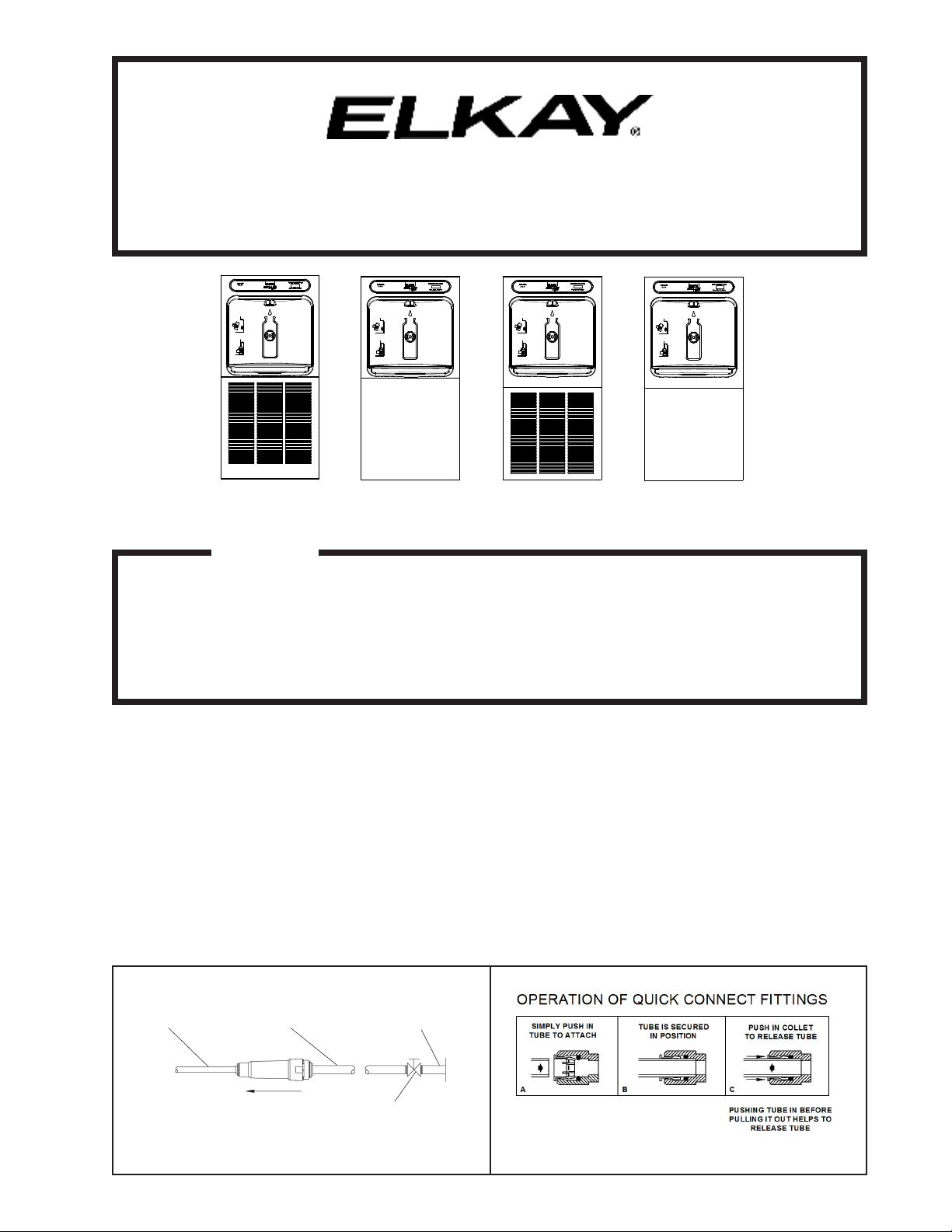
1/4” O.D. TUBE
WATER INLET
TO COOLER
Page 1 98557C (Rev. K - 11/14)
3/8” O.D. TUBE CONNECT
COLD WATER SUPPLY
NOTE: WATERFLOW
DIRECTION
BUILDING WATER
INLET
SERVICE STOP
(NOT FURNISHED)
FIG. 2FIG. 1
Page 2
EZWSMD*1A EZWSM8*1A EZWSM8*2A LZWSMD*1A LZWSM8*1A LZWSM8*2A
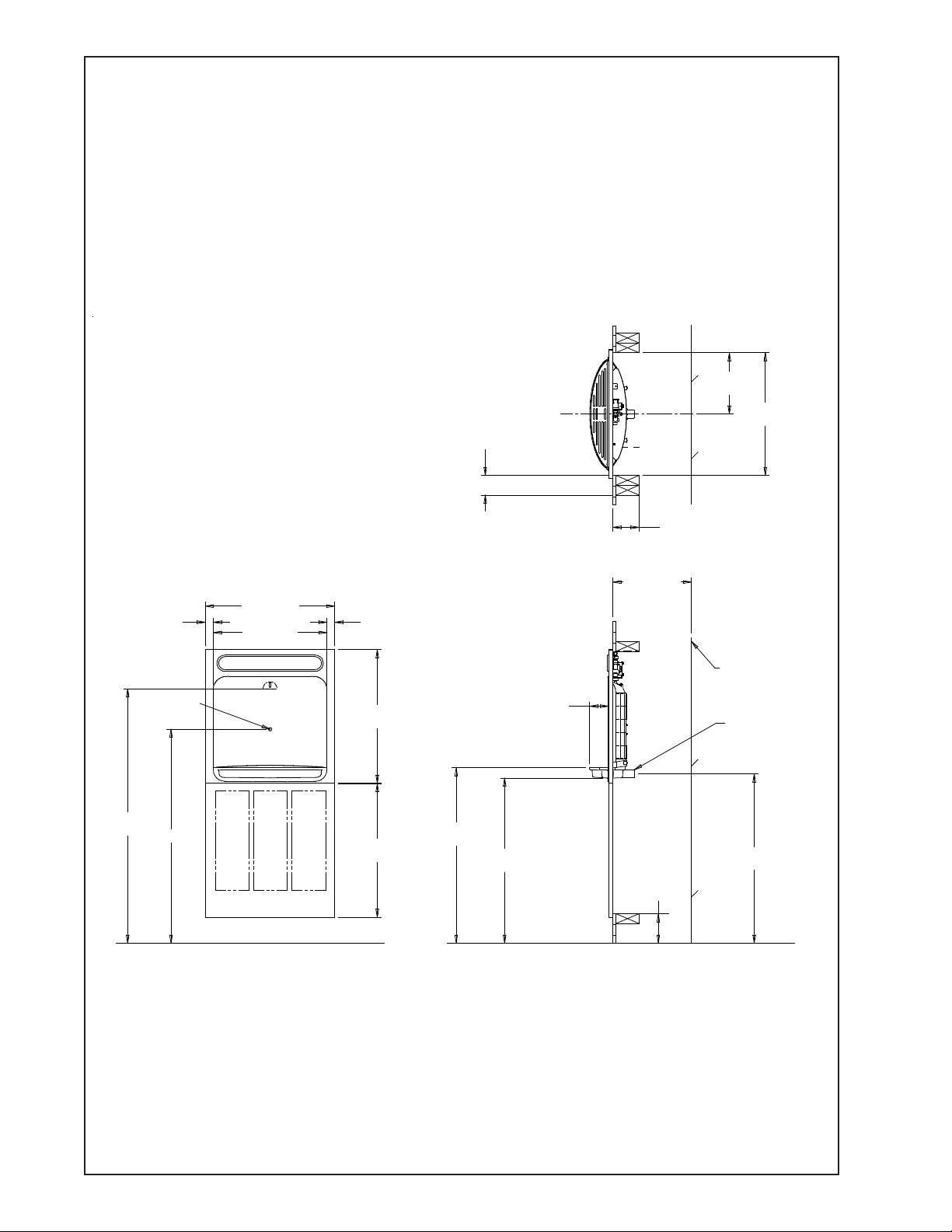
LZWSM8*, LZWSMD* EZWSM8*, EZWSMD* ROUGH-IN
9 3/8"
( 238mm )
DOUBLE STUD OR 3" (76mm)
BETWEEN MOUNTING FRAMES
IF PLACED NEXT TO ANOTHER
FOUNTAIN OR WALL
18 3/4"
( 476mm )
1 3/16"
( 30mm )
ACTIVATION
SENSOR
38 7/8"
( 987mm )
32.673
19 3/4"
( 502mm )
17 3/8"
( 441mm)
FINISHED FLOOR
1 3/16"
( 30mm )
20 3/8"
( 518mm)
20 7/16"
( 519mm)
27"
( 681mm)
2 7/8"
( 73mm )
25 1/4"
( 641mm)
FINISHED FLOOR
( 102mm)
12"
( 305mm )
MINIMUM
DEPTH
4 1/2"
( 114mm)
4"
BACK WALL LINE
1-1/4" (32MM)
WASTE TUBE
FURNISHED
25 7/8"
( 657mm )
FIG. 3
98557C (Rev. K - 11/14) Page 2
Page 3
EZWSMD*1A EZWSM8*1A EZWSM8*2A LZWSMD*1A LZWSM8*1A LZWSM8*2A
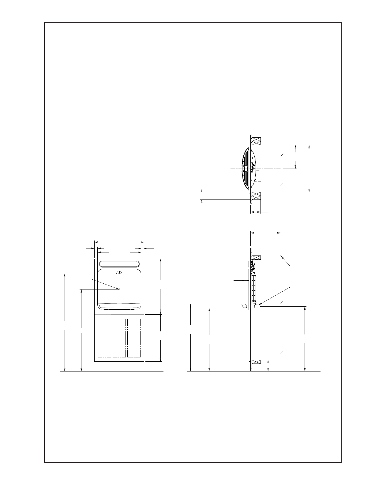
LZWSM8P*, LZWSMDP* EZWSM8P*, EZWSMDP* ROUGH-IN
9 3/8"
( 238mm )
DOUBLE STUD OR 3" (76mm)
BETWEEN MOUNTING FRAMES
IF PLACED NEXT TO ANOTHER
FOUNTAIN OR WALL
18 3/4"
( 476mm )
1 3/16"
( 30mm )
ACTIVATION
SENSOR
38 7/8"
( 987mm )
32.673
19 3/4"
( 502mm )
17 3/8"
( 441mm)
FINISHED FLOOR
1 3/16"
( 30mm )
21 15/16"
( 557mm)
18 7/8"
( 481mm)
27"
( 681mm)
2 7/8"
( 73mm )
25 1/4"
( 641mm)
FINISHED FLOOR
( 102mm)
12"
( 305mm )
MINIMUM
DEPTH
4 1/2"
( 114mm)
4"
BACK WALL LINE
1-1/4" (32MM)
WASTE TUBE
FURNISHED
25 7/8"
( 657mm )
FIG. 4
Page 3 98557C (Rev. K - 11/14)
Page 4

EZWSMD*1A EZWSM8*1A EZWSM8*2A LZWSMD*1A LZWSM8*1A LZWSM8*2A
INSTALLATION INSTRUCTIONS
1. Install mounting frame. See mounting frame instructions.
2. Install remote chiller. See chiller instructions.
3. EWF3000 WATERSENTRY PLUS FILTER INSTALLATION
(Filtered units only. For non ltered units proceed to step 4b)
NOTICE: Do not use with water that is microbiologically unsafe or of
unknown quality without adequate disinfection before or after the system.
1)These lter kits must be installed in compliance with all state and local laws
and regulations governing the installation and use of this product. Maximum
inlet water temperature 100°F (38°C).
2) See lter instructions for lter assembly. Insert 3/8" elbow tting into the
inlet side of lter head, insert 1/4" polytube or 1/4" x 90° elbow into outlet
of lter head prior to mounting the lter head assembly into the remote chiller.
3) Mount lter head to the side of the remote chiller using the lter mounting bracket and screws supplied.
CAUTION: If supply pressure will ever exceed 100 psi, install a pressure
regulator to limit the inlet pressure to the lter to 100 psi or below.
DO NOT ATTACH HOT WATER LINE TO FILTER. To make connections on the
lter head, loosen locknut. Push the tube end past both o-rings to a positive
stop in the lter head recess - approx. 1", locknut may have to be backed out a
little more. Screw the locknut hand tight to seal (See Fig. 5). Ends of tubing
must be cut square and free of burrs and sharp ends that could cut or nick the o-rings.
NOTE: SCREW THE LOCK-
NUT HAND TIGHT TO SEAL
FIG. 5
4a. Make water supply connections for Fltered units. Install a shut-off valve and union connection to building water supply (valve
and union not provided). Turn on the water supply and ush the line thoroughly.
4b. Make water supply connections for Non Fltered units. Install a shut-off valve and union connection to building water supply
(valve and union not provided). Turn on the water supply and ush the line thoroughly. Install the in-line strainer between the
valve and the cooler. The in-line strainer is not installed on ltered units.
5. (Filtered units only. For non ltered units proceed to step 7)
Make connection between lter head and building supply line. Insert the 3/8" water line into the inlet side of the lter head by
pushing it in until it reaches a positive stop, approximately 3/4" (19mm). Install two 1/4" x 1/4" unions (provided) on the chiller.
One on the inlet tube, and the other on the outlet tube.
6. Make connection between the lter head and the remote chiller. Insert end of 1/4" O.D. poly tubing from the lter head (pro-
vided) into union on chiller inlet.
7. Mount the upper panel to the mounting frame, aligning holes in the hinge brackets with holes in the mounting frame (three
places). Mount with adequate size screws (not provided). Close the door and verify that the lock brackets on the side and
bottom of the panel align with the slots on the mounting frame. Also verify that the panel is hanging high enough that it covers
the top of the mounting frame. If adjustments need to be made, open the door and loosen the three screws on the hinge and
adjust accordingly and then retighten the screws.
8. Connect water line from the water station by inserting the 1/4" O.D. poly tubing into the union on the chiller outlet.
9. Close the upper door and attach the drain ttings to drain tube. Re-attach elbow to p-trap and cut waste tube to required
length using plumbing hardware and trap as a guide.
PLUMBING DIAGRAM
FIG. 6
TO BOTTLE FILLER
TO BOTTLE FILLER
INLET
STRAINER
INLET
CHILLER
98557C (Rev. K - 11/14) Page 4
FILTER
CHILLER
NON FILTEREDFILTERED
Page 5

EZWSMD*1A EZWSM8*1A EZWSM8*2A LZWSMD*1A LZWSM8*1A LZWSM8*2A
10. Lock the door in place using two set screws (provided) on the side of the panel, and a ¼ x 20 bolt through the front of the panel
into the nut in the frame.
11. (Filtered units only) Install lter cartridge, remove lter from carton, remove protective cap, attach lter to lter head by rmly
inserting into head and rotating lter clockwise.
12. Turn water supply on and inspect for leaks. Fix all leaks before continuing.
13. Once unit has been inspected for leaks, and any leaks found corrected, plug Bottle Filler into wall (power cord not supplied on
220V models). Be sure to reinstall fuse to the circuit or switch the circuit breaker back to the “ON” position.
14a. (Filtered units) Once power is applied to Bottle Filler, the GREEN LED light should illuminate showing good lter status along
with the LCD Bottle Counter.
14b.(Non Filtered units) Once power is applied to Bottle Filler, the LCD Bottle Counter should illuminate.
15. Verify proper dispensing by placing cup, hand, or any opaque object in front of sensor area and verify water dispenses.
Note: the rst initial dispenses might have air in line which may cause a sputter. This will be eliminated once all air is purged
from the line. A steady stream of water assures all air is removed. The sensor has a 30 second maximum ON time. It may be
necessary to step away from beam a few times to allow chiller tank to rell. Check for leaks.
16. Mount the lower panel to the mounting frame, aligning holes in the hinge brackets with holes in the mounting frame (three
places). Mount with adequate size screws (not provided). Close the door and verify that the lock brackets on the side of the
panel align with the slots on the mounting frame. If adjustments need to be made, open the door and loosen the three screws
on the hinge and adjust accordingly and then retighten the screws.
17. Lock the lower door in place using two set screws (provided) on the side of the panel.
MOUNTING FRAME
UPPER PANEL
LOWER PANEL
FILTER LOCA-
TION
(OPTIONAL)
HINGE BRACKETS
DRAIN LOCATION
CHILLER
FIG. 7
Page 5 98557C (Rev. K - 11/14)
Page 6

EZWSMD*1A EZWSM8*1A EZWSM8*2A LZWSMD*1A LZWSM8*1A LZWSM8*2A
BF6-BF7-BF8 PROGRAMS
SETTING THE CONTROL BOARD
VERIFY CONTROL BOARD SOFTWARE
1) To verify the software program of the control board the
unit will need to be shut down and restarted. The chiller
(if present) does not need to be shut down and restarted.
2) The units lower panel must be open to access the power
cord and wall outlet.
3) Shut down the unit by unplugging the power cord from the
wall outlet.
4) Restart the unit by plugging the power cord back into the
wall outlet.
5) Upon start up the bottle count display will show the
software designation of BF6, BF7, BF8, BF9 or BF11.
6) Reference the BF6-BF7-BF8-BF9 or BF11 instructions for
setting the control board.
ACCESSING THE PROGRAMMING BUTTON
1) To access the program button the lower panel of the
unit must be must be opened. The programming button is
located at the bottom right corner of the upper panel.
This area of the unit is concealed by the lower panel.
1) Depress the program button for approximately 2 seconds
RESETTING BOTTLE COUNT
until the display changes then release. The display will
change and scroll through two messages:
“RST FLTR” – Reset Filter Status LED
“RST BCNT” – Reset Bottle Count
“RNG SET” – Range Set for IR Sensor
If the program button is not pushed again the display
will scroll through the two messages above for
three cycles and then default back to bottle count
and be back in run mode.
2) When the display changes to "RST BCNT", depress the
button again. The display will change to show current
bottle count value e.g. "00033183".
3) Depress the button again and the display will change to
"BTLCT=0" for approximately 2 seconds and then return
to run mode displaying 00000000.
4) You can test the bottle counter by running water
approximately 5 seconds to see bottle counter advance 1.
1) Instructions apply to ltered units only.
2) Depress the program button for approximately 2 seconds
until the display changes then release. The display will
change and scroll through three messages:
“RST FLTR” – Reset Filter Status LED
“RST BCNT” – Reset Bottle Count
“RNG SET” – Range Set for IR Sensor
If the program button is not pushed again the display
will scroll through the three messages above for
three cycles and then default back to bottle count and
be back in run mode.
3) When the display changes to "RST FLTR", depress
the button again. The display will change to show
"FLT=". Depress the button again and the display will
show "FLTR=0".
4) The green LED should now be illuminated indicating
that the visual lter monitor has been reset.
1) Depress the program button for approximately 2 seconds
until the display changes then release. The display will
change and scroll through three messages:
“RST FLTR” – Reset Filter Status LED
“RST BCNT” – Reset Bottle Count
“RNG SET” – Range Set for IR Sensor
2) If the program button is not pushed again the display
will scroll through the two messages above for
three cycles and then default back to bottle count
and be back in run mode.
3) When display shows “RNG SET” push program button
once the display will show current value
(can be 1 – 10) e.g. “RNG = 3”.
4) Once display shows current value push the program
button to scroll through value of 1 – 10. Select the
desired range setting.
5) Once range is selected allow approximately 4 seconds
to pass and then the display will go back to bottle counter
and be in run mode.
6) Test bottle ller by placing bottle or hand in front of
sensor to make sure water is dispensed.
RESET THE FILTER MONITOR
SETTING RANGE OF THE IR SENSOR
98557C (Rev. K - 11/14) Page 6
Page 7

EZWSMD*1A EZWSM8*1A EZWSM8*2A LZWSMD*1A LZWSM8*1A LZWSM8*2A
SETTING THE CONTROL BOARD
VERIFY CONTROL BOARD SOFTWARE
1) To verify the software program of the control board the
unit will need to be shut down and restarted. The chiller
(if present) does not need to be shut down and restarted.
2) The units lower panel must be open to access the power
cord and wall outlet.
3) Shut down the unit by unplugging the power cord from the
wall outlet.
4) Restart the unit by plugging the power cord back into the
wall outlet.
5) Upon start up the bottle count display will show the
software designation of BF6, BF7, BF8, BF9 or BF11.
6) Reference the BF6-BF7-BF8-BF9 or BF11 instructions for
setting the control board.
ACCESSING THE PROGRAMMING BUTTON
1) To access the program button the lower panel of the
unit must be must be opened. The programming button is
located at the bottom right corner of the upper panel.
This area of the unit is concealed by the lower panel.
RESET THE FILTER MONITOR
1) Instructions apply to ltered units only.
2) Depress the program button for approximately 2 seconds
until the display changes then release. The display will
change and scroll through two messages:
“RST FLTR” – Reset Filter Monitor
“SETTINGS” – System Settings Sub Menu
If the program button is not pushed again the display
will scroll through the two messages above for
three cycles and then default back to bottle count and
be back in run mode.
3) When the display changes to “RST FLTR”, depress
the button again. The display will change to show
“FLTR =”. Depress the button again and the display
will show “FLTR =0”
4) The Green LED should be illuminated indicating that
the visual lter monitor has been reset.
SETTING RANGE OF THE IR SENSOR
1) Depress the program button for approximately 2 seconds
until the display changes then release. The display will
change and scroll through two messages:
“RST FLTR” – Reset Filter Status LED
“SETTINGS” – System Settings Sub Menu
If the program button is not pushed again the display
will scroll through the two messages above for
three cycles and then default back to bottle count
and be back in run mode.
2) When the display changes to “SETTINGS”, depress
the button again. The display will change to show
“RNG SET“- Range set for IR sensor.
“UNIT TYP“ - Type of unit (REFRIG or NON-RFRG)
“RST BCNT“ - Reset bottle count
3) When display shows “RNG SET” push program
button once the display will show current value
(can be 1 – 10) e.g. “RNG = 3”.
4) Once display shows current value push the
program button to scroll through value of 1 – 10.
Select the desired range setting.
5) Once range is selected allow approximately
4 seconds to pass and then the display will go
back to bottle counter and be in run mode.
6) Test bottle ller by placing bottle or hand in front
of sensor to make sure water is dispensed.
BF9 PROGRAM
SETTING UNIT TYPE
1) Depress the program button for approximately 2 seconds
until the display changes then release. The display will
change and scroll through two messages:
“RST FLTR” – Reset Filter Status LED
“SETTINGS” – System Settings Sub Menu
If the program button is not pushed again the display
will scroll through the two messages above for
three cycles and then default back to bottle count
and be back in run mode.
2) When the display changes to “SETTINGS”, depress
the button again. The display will change to show
“RNG SET“- Range set for IR sensor.
“UNIT TYP“ - Type of unit (REFRIG or NON-RFRG)
“RST BCNT“ - Reset bottle count
3) When display shows “UNIT TYPE” push program
button once the display will show current value
Can be REFRIG or NON-RFRG
4) Push button once to change value. Once value is
selected the display will show the new value.
(Can be REFRIG or NON-RFRG)
“REFRIG“ - stands for refrigerated product. In this
setting the ow rate is estimated at 1.0 gallon per minute.
“NON-RFRG“ - stands for nonrefrigerated product.
In this setting the ow rate is estimated
at 1.5 gallons per minute.
Both “REFRIG“ and “NON-RFRG“ simulate
1 bottle equal to 20 oz.
5) Allow approximately 4 seconds to pass and the display
will return to bottle counter and be in run mode.
RESETTING BOTTLE COUNT
1) Depress the program button for approximately 2 seconds
until the display changes then release. The display will
change and scroll through two messages:
“RST FLTR” – Reset Filter Status LED
“SETTINGS” – System Settings Sub Menu
If the program button is not pushed again the display
will scroll through the two messages above for
three cycles and then default back to bottle count
and be back in run mode.
2) When the display changes to “SETTINGS”, depress
the button again. The display will change to show
“RNG SET“- Range set for IR sensor.
“UNIT TYP“ - Type of unit (REFRIG or NON-RFRG)
“RST BCNT“ - Reset bottle count
If the button is not pushed again the display will scroll
through the three messages above for the cycles and
return to run mode.
3) When display shows “RST BCNT” push program button
once the display will show current value e.g. “00033183”.
4) Once display shows current value push the program
button once more to reset back to 0. The display will
show BTLCT = 0 for approximately 2 seconds and
then return to run mode showing 00000000 bottles.
5) Testing the bottle counter:
REFRIG units: Place bottle or hand in front of sensor
for 9.4 seconds to see bottle counter count 00000001.
(This is based on lling a 20 oz. bottle)
NON-RFRG units: Place bottle or hand in front of sensor
for 6.25 seconds to see bottle counter count 00000001.
(This is based on lling a 20 oz bottle)
Page 7 98557C (Rev. K - 11/14)
Page 8

EZWSMD*1A EZWSM8*1A EZWSM8*2A LZWSMD*1A LZWSM8*1A LZWSM8*2A
BF11 PROGRAM
SETTING THE CONTROL BOARD
1) To verify the software program of the control board the
VERIFY CONTROL BOARD SOFTWARE
unit will need to be shut down and restarted. The chiller
(if present) does not need to be shut down and restarted.
2) The units lower panel must be open to access the power
cord and wall outlet.
3) Shut down the unit by unplugging the power cord from the
wall outlet.
4) Restart the unit by plugging the power cord back into the
wall outlet.
5) Upon start up the bottle count display will show the
software designation of BF6, BF7, BF8, BF9 or BF11.
6) Reference the BF6-BF7-BF8-BF9 or BF11 instructions for
setting the control board.
ACCESSING THE PROGRAMMING BUTTON
1) To access the program button remove the top cover of
the bottle ller. Remove the two (2) screws holding top
cover to bottle ller with a 5/32” allen wrench . Remove
top cover. Do not discard mounting screws, they will be
needed to reinstall the top cover after programming
operations are completed. The programming button is
located at the top right side of the unit on the control board.
RESET THE FILTER MONITOR
1) Instructions apply to ltered units only.
2) Depress the program button for approximately 2 seconds
until the display changes then release. The display will
change and scroll through two messages:
“RST FLTR” – Reset Filter Monitor
“SETTINGS” – System Settings Sub Menu
If the program button is not pushed again the display
will scroll through the two messages above for
three cycles and then default back to bottle count and
be back in run mode.
3) When the display changes to “RST FLTR”, depress
the button again. The display will change to show
“FLTR =”. Depress the button again and the display
will show “FLTR =0”
4) The Green LED should be illuminated indicating that
the visual lter monitor has been reset.
SETTING RANGE OF THE IR SENSOR
1) Depress the program button for approximately 2 seconds
until the display changes then release. The display will
change and scroll through two messages:
“RST FLTR” – Reset Filter Status LED
“SETTINGS” – System Settings Sub Menu
If the program button is not pushed again the display
will scroll through the two messages above for
three cycles and then default back to bottle count
and be back in run mode.
2) When the display changes to “SETTINGS”, depress
the button again. The display will change to show
“RNG SET” - Range set for IR sensor.
“UNIT TYP” - Type of unit (REFRIG or NON-RFRG)
“FLT SIZE” - Select lter capacity
“RST BCNT” - Reset bottle count
3) When display shows “RNG SET” push program
button once the display will show current value
(can be 1 – 10) e.g. “RNG = 3”.
4) Once display shows current value push the
program button to scroll through value of 1 – 10.
Select the desired range setting.
5) Once range is selected allow approximately
4 seconds to pass and then the display will go
back to bottle counter and be in run mode.
6) Test bottle ller by placing bottle or hand in front
of sensor to make sure water is dispensed.
1) Depress the program button for approximately 2 seconds
until the display changes then release. The display will
change and scroll through two messages:
“RST FLTR” – Reset Filter Status LED
“SETTINGS” – System Settings Sub Menu
If the program button is not pushed again the display
will scroll through the two messages above for
three cycles and then default back to bottle count
and be back in run mode.
2) When the display changes to “SETTINGS”, depress
the button again. The display will change to show
“RNG SET” - Range set for IR sensor.
“UNIT TYP” - Type of unit (REFRIG or NON-RFRG)
“FLT SIZE” - Select lter capacity
“RST BCNT” - Reset bottle count
3) When display shows “UNIT TYPE” push program
button once the display will show current value
Can be REFRIG or NON-RFRG
4) Push button once to change value. Once value is
selected the display will show the new value.
(Can be REFRIG or NON-RFRG)
“REFRIG“ - stands for refrigerated product. In this
setting the ow rate is estimated at 1.0 gallon per minute.
“NON-RFRG“ - stands for nonrefrigerated product.
In this setting the ow rate is estimated
at 1.5 gallons per minute.
Both “REFRIG“ and “NON-RFRG“ simulate
1 bottle equal to 20 oz.
5) Allow approximately 4 seconds to pass and the display
will return to bottle counter and be in run mode.
1) Depress the program button for approximately 2 seconds
until the display changes then release. The display will
change and scroll through two messages:
“RST FLTR” – Reset Filter Status LED
“SETTINGS” – System Settings Sub Menu
If the program button is not pushed again the display
will scroll through the two messages above for
three cycles and then default back to bottle count
and be back in run mode.
2) When the display changes to “SETTINGS”, depress
the button again. The display will change to show
“RNG SET”- Range set for IR sensor.
“UNIT TYP” - Type of unit (REFRIG or NON-RFRG)
“FLT SIZE” - Select lter capacity
“RST BCNT” - Reset bottle count
If the button is not pushed again the display will scroll
through the four messages above for three cycles and
return to run mode.
3) When display shows “RST BCNT” push program button
once the display will show current value e.g. “00033183”.
4) Once display shows current value push the program
button once more to reset back to 0. The display will
show BTLCT = 0 for approximately 2 seconds and
then return to run mode showing 00000000 bottles.
5) Testing the bottle counter:
REFRIG units: Place bottle or hand in front of sensor
for 9.4 seconds to see bottle counter count 00000001.
(This is based on lling a 20 oz. bottle)
NON-RFRG units: Place bottle or hand in front of sensor
for 6.25 seconds to see bottle counter count 00000001.
(This is based on lling a 20 oz bottle)
CONTINUED ON
SETTING UNIT TYPE
RESETTING BOTTLE COUNT
PAGE 9
98557C (Rev. K - 11/14) Page 8
Page 9

EZWSMD*1A EZWSM8*1A EZWSM8*2A LZWSMD*1A LZWSM8*1A LZWSM8*2A
BF11 PROGRAM
SETTING THE CONTROL BOARD
1) Depress the program button for approximately 2 seconds
until the display changes then release. The display will
change and scroll through two messages:
“RST FLTR” – Reset Filter Status LED
“SETTINGS” – System Settings Sub Menu
If the program button is not pushed again the display
will scroll through the two messages above for
three cycles and then default back to bottle count
and be back in run mode.
2) When the display changes to “SETTINGS”, depress
the button again. The display will change to show
“RNG SET“- Range set for IR sensor.
“UNIT TYP“ - Type of unit (REFRIG or NON-RFRG)
“FLT SIZE” - Select lter capacity
“RST BCNT“ - Reset bottle count
If the button is not pushed again the display will scroll
through the four messages above for three cycles and
return to run mode.
3) When display shows “FLT SIZE” push program button
once. The display will show current value. Can be
3000GAL or 6000GAL.
4) Push program button again to display the desired “FLT SIZE”.
5) Allow approximately 4 seconds to pass and the display will
return to bottle counter and be in run mode.
SETTING FILTER CAPACITY
Page 9 98557C (Rev. K - 11/14)
Page 10

EZWSMD*1A EZWSM8*1A EZWSM8*2A LZWSMD*1A LZWSM8*1A LZWSM8*2A
WATERSENTRY® PLUS FILTER PARTS LIST
(See Fig. 8)
ITEM
NO.
1
2
3
4
5
6
7
2
PART NO.
51294C
70792C
70823C
70822C
51300C
70818C
22490C
DESCRIPTION
Filter Head Assy.
Screw #8-18 x .75 PH
Fitting - Superseal 3/8” (10 mm)
Fitting - Superseal 1/4” (6 mm)
Filter Assy
Elbow - 3/8” (10mm)
Bracket
7
4
3
1
5
LISTA DE PIEZAS DEL
FILTRO (Vea Fig. 8)
DESCRIPCIÓN DESCRIPTION
Ensamblado de la Cabeza del Filtro
Tornillo #8-18 x .75 PH
Accesorio - Supersello 3/8" (10mm)
Accesorio - Supersello 1/4" (6 mm)
Ensamblado del Filtro
Codo - 3/8" (10 mm)
Fijador
6
LISTE DES PIÈCES DU FIL-
TRE (Voir Fig. 8)
Ens. de tête de ltre
Vis #8-18 x .75 hp
Raccord - Superseal 3/8" (10mm)
Raccord - Superseal 1/4" (6mm)
Ens. ltre
Coude - 3/8" (10mm)
Support
PRINTED IN U.S.A.
IMPRESO EN LOS E.E.U.U.
IMPRIMÉ AUX É.-U.
WATER FILTER EXPLODED
VIEW
FIG. 8
FIG. 9
REPLACEMENT PART KITS
PART NO.
98543C
98544C
98545C
98546C
98549C
98631C
98632C
REPAIR SERVICE INFORMATION TOLL FREE NUMBER 1.800.260.6640
INFORMATIONS POUR LE SERVICE PAR NUMERO SANS FRAIS 1.800.260.6640
FOR PARTS, CONTACT YOUR LOCAL DISTRIBUTOR OR CALL 1.800.834.4816
POUR OBTENIR DES PIÈCES, CONTACTEZ VOTRE DISTRIBUTEUR LOCAL OU COMPOSEZ LE 1.800.834.4816
PARA PIEZAS, CONTACTE A SU DISTRIBUIDOR LOCAL O LLAME AL 1.800.834.4816
ELKAY MANUFACTURING COMPANY • 2222 CAMDEN COURT • OAK BROOK, IL 60523 • 630.574.8484
NÚMERO GRATIS DE SERVICIO 1.800.260.6640
DESCRIPTION
Kit - Electrical Package
Kit - EE Sensor
Kit - Solenoid Valve Replacement
Kit - Aerator Replacement
Kit - Hardware & Waterway Parts
Kit - Electrical Package 220V
Kit - Solenoid Valve Replacement 220V
98557C (Rev. K - 11/14) Page 10
 Loading...