

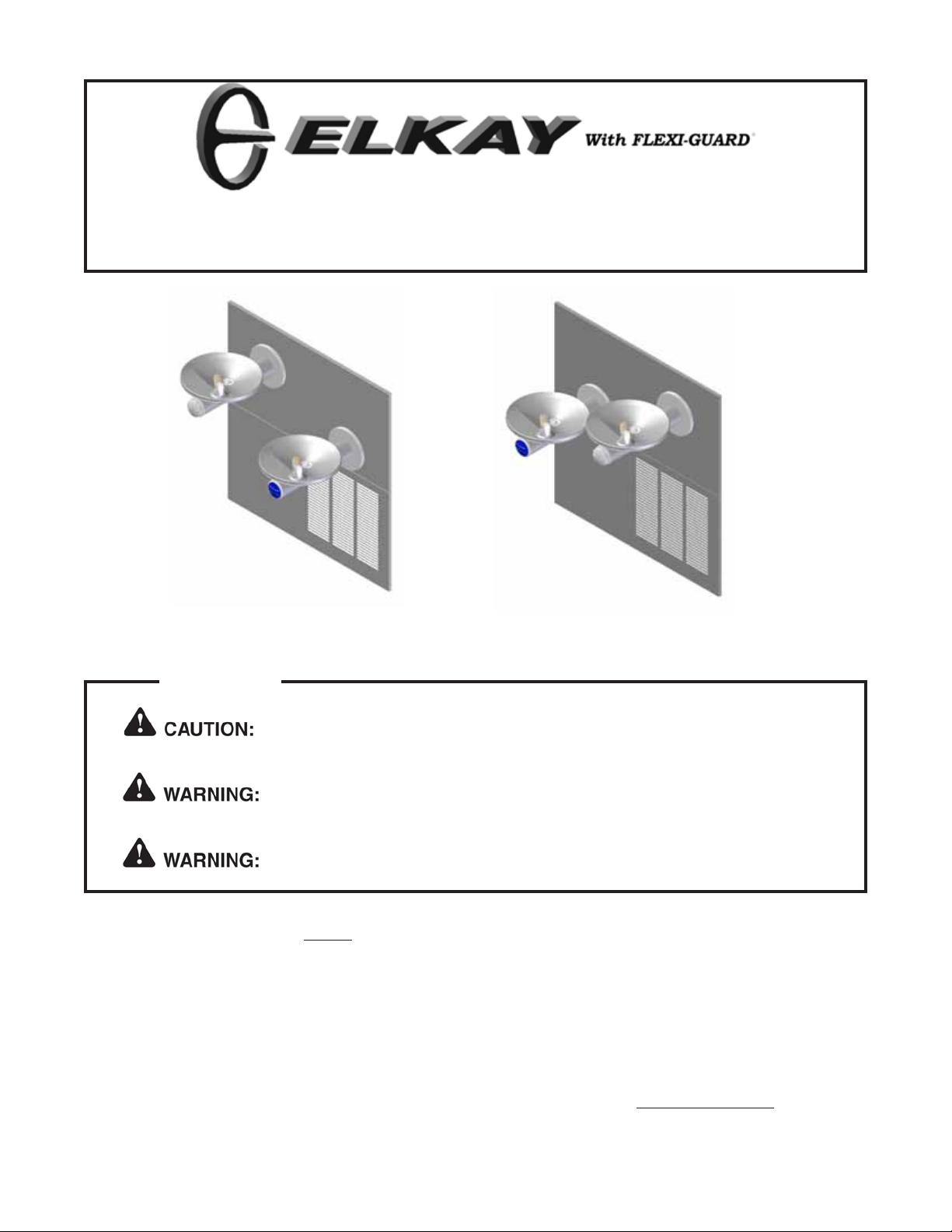
ENOB2-8C, ENOB2-8RAC
INSTALLATION, CARE & USE MANUAL
TM
SWIRLFLO Refrigerated fountains with FLEXI-GUARD
ENOB2-8C ENOB2-8RAC
TM
INSTALLER
Review these instructions before beginning installation. Be sure that installation
conforms to all plumbing, electrical and other applicable codes.
When installation is complete, ensure these instructions are left with building owner
for future reference.
Service to be performed by authorized service personnel only .
NOTE: It is common practice to ground electrical hardware such as telephones, computers and other devices to
available water lines. This can, however , cause electrical feedback in the plumbing circuit, which results in
an “electrolysis” effect occurring in the fountain. This may result in water which has a metallic taste to it or
has a noticeable increase in the metallic content of the water.
When inspecting plumbing circuit, remember the line may be grounded some distance from the installation,
and may occur outside the building or area in which the unit is being installed.
This condition can be avoided (in most cases) by using recommended materials during installation. Any
drain fittings provided by the installer should be made of plastic which will electronically isolate the fountain
from the remainder of the building’s plumbing circuits.
1
98005C (REV. B - 3/05)
1 1/8"
29mm
11"
279mm
8"
203mm
4 1/2"
114mm
28 3/4"
730mm
12"
305mm
5/8"
16mm
41 11/16"
1060mm
33 15/16"
863mm
1 5/8"
41mm
1 5/8"
41mm
C
D
36 1/2"
926mm
FINISHED FLOOR
MINIMUM DEPTH
18 3/4"
476mm
9 3/8"
238mm
8 1/8"
206mm
A
B
1 1/8"
29mm
3 1/8"
79mm
18 3/8"
467mm
27"
686mm
ADA
REQUIREMENT
BACK WALL LINE
ENOB2-8C, ENOB2-8RAC
36 1/2"
927mm
28 3/4"
730mm
18 3/4"
476mm
3 1/8"
80mm
1 1/8"
29mm
A
B
Model ENOB2-8C Model ENOB2-8RAC
98005C (REV. B - 3/05)
9 3/8"
238mm
8 1/8"
206mm
BACK WALL LINE
C
5/8"
16mm
12"
305mm
MINIMUM DEPTH
18 3/8"
467mm
1 5/8"
41mm
1 5/8"
41mm
33 15/16"
863mm
41 11/16"
1059mm
8"
203mm
4 1/2"
114mm
1 1/8"
29mm
11"
D
FINISHED FLOOR
27"
686mm
ADA
REQUIREMENT
LEGEND
2
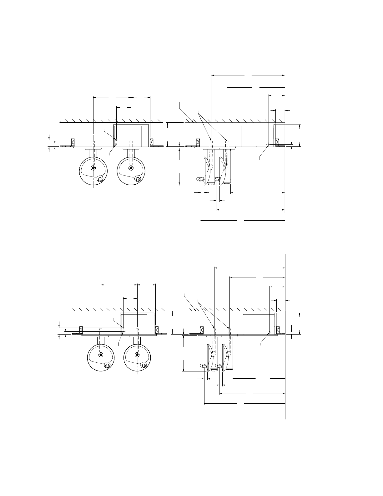
Figure 1 - Rough-in Dimensions
279mm
A = 1/4” O.D. Tube - Water Outlet Connection
B = 3/8” O.D. Tube - Water Inlet Connection
C = 1-1/4” Waste Tube
D = ELECTRICAL INLET
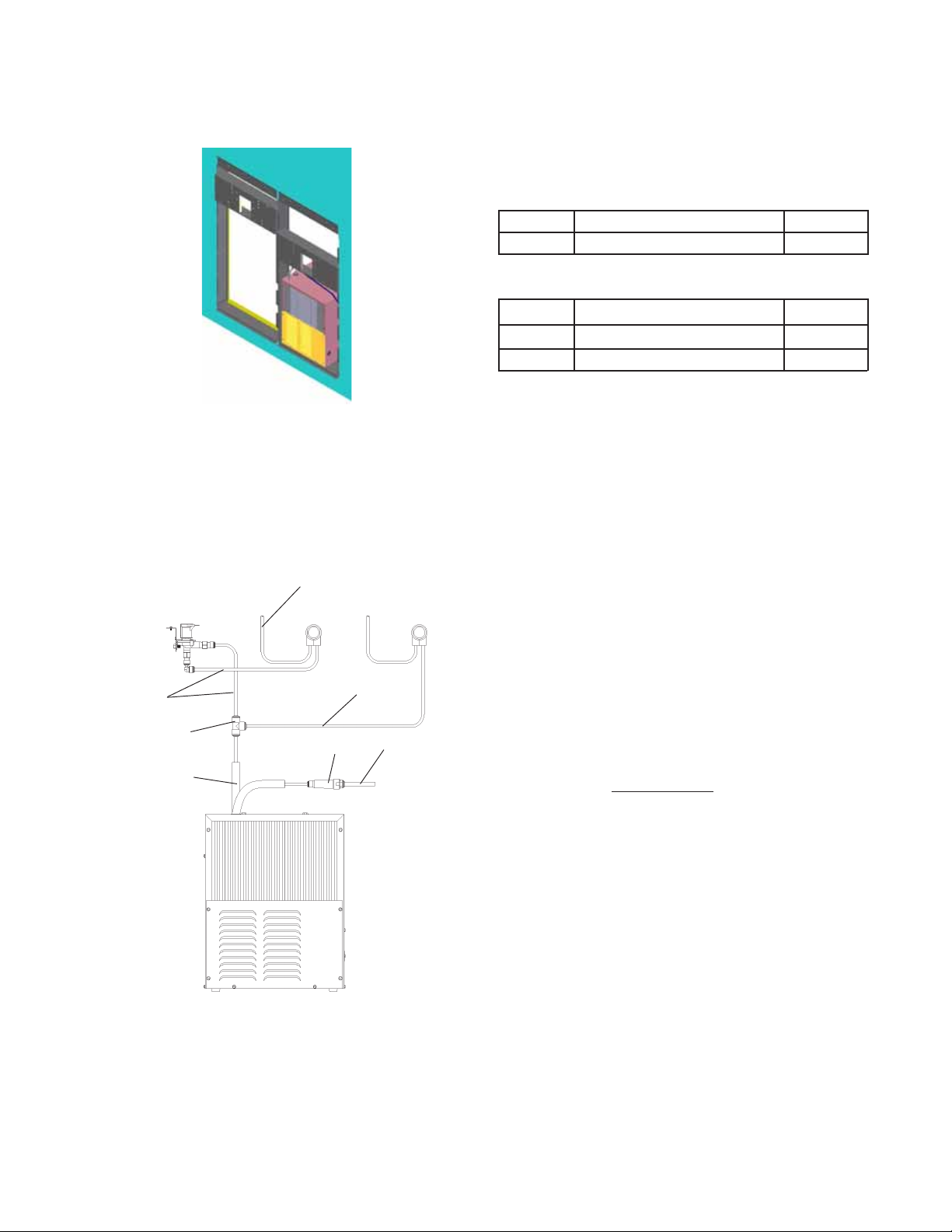
Figure 2 - Chiller Installation
ENOB2-8C, ENOB2-8RAC
REQUIRED TOOLS AND MA TERIALS
These tables show special tools and/or
additional materials (not provided) which are
necessary to complete installation of these
units:
Special Tools
Item Description Quantity
NONE
Additional Materials
Item Description Quantity
1 Unplated copper inlet pipe
2 Service Stop
1. Install chiller: Remove front panel of chiller. Slide chiller onto
the shelf and position it to the left as per dimensions
in Figure 1.
Note: Building construction must allow for
adequate air flow on both sides, top and
back of chiller. A minimum of 4” (102mm) on
both sides and top is required. See chiller
installation for additional instructions.
21
22
CHILLER
OUTLET
TO BUBBLER
21
23
CHILLER
INLET
2. Attach solenoid valve assembly to the underside of
cross member of mounting frame on electronic
sensor unit. (See Fig. 7).
3. Make water supply connections. Inlet port is marked on
the chiller (1/4” O.D. copper tube). Bend the copper tube
(provided) at an appropriate length from the chiller to
opening in frame. Install the in-line strainer (provided with
chiller) by pushing it in until it reaches a positive stop,
approximately 3/4” (19mm) on the marked chiller inlet port
(See Figs. 3) (Refer to Fig. 13 on page 7 for details on
assembling quick connect fittings). Attach an unplated and
deburred copper water inlet line and a service stop (not
provided) to the chiller. Turn on the water supply and flush
the line thoroughly.
Caution: DO NOT SOLDER tubes inserted
into the strainer as damage to
o-rings may result.
4. Make connection between remote chiller outlet tube
and solenoid valve assembly. Outlet port is marked on
the chiller (1/4” O.D. copper tube). Install a 1/4” tee
(provided) on the marked chiller outlet port. Insert one end of
1/4” poly tubing into the tee and the other end into the
straight fitting on the solenoid valve assy. (See Fig. 3)
5. Hang the upper panel on the mounting frame hanger. Be
sure that the panel is engaged with hanger at the top of
frame before releasing it. Align holes in the panel with holes
in the mounting frame. Install two (2) #10-24 x 5/8” (16mm)
screws (Item 27 - Figure 4) in holes and tighten securely.
Figure 3 - ENO Tube Routing
6. Install the fountain. Remove the screw (Item 28) from cover
plate (Item 12) and slide cover plate toward basin. Mount the
fountain to the upper panel and frame with (4) 5/16” x 1”
(25mm) long bolts (Item 30), bracket (Item 34) and nuts
(Item 33) provided. Tighten securely. Brackets (Item 34)
must be installed as shown to properly support
fountain. (See Fig. 5)
3
98005C (REV. B - 3/05)

ENOB2-8C, ENOB2-8RAC
7. Attach waste tube (1-1/4” O.D.) to 1-1/4” O.D. slip
trap (provided by others).
Figure 4 - Upper Panel Installation
30
11
28
34
33
View From Rear
Figure 5 - Fountain Installation
24, 25
27
27
8. Connect the fountain drain waste tube to the building
sanitary sewer system. Connection should be made in
compliance with local plumbing code requirements. (Note:
Plumbing trap is not included with the fountain).
9. Make connection between solenoid valve assembly
and fountain(s). Insert the 1/4” poly tubing coming from the
fountain with sensor into the solenoid valve. Insert the 1/4”
poly tubing coming from the fountain with push button into the
tee (See Fig. 3).
10. Connect power cord of sensor to solenoid valve
assembly by running it through the back panel and
connecting it to terminal as shown in Fig. 8.
11. Turn on water supply and check for leaks. Release air
from tank by interrupting infrared beam; a steady stream of
water assures all air is removed. The sensor has a 30 second
maximum ON time. It may be necessary to step away from
beam a few times to allow chiller tank to fill.
DO NOT SOLDER tubes while
inserted into the strainer as damage
to o-rings may result.
12. These products are designed to operate on 20-105
PSIG supply line pressure. If inlet pressure is above 105
PSIG, a pressure regulator must be installed in the supply line.
Any damage caused byconnecting
these products to a supply line with
pressure lower than 20 PSIG or
higher than 105 PSIG
IS NOT covered
under warranty.
13. Make electrical connections to the chiller. See chiller
instructions.
14. Check stream height from bubbler. Stream height is
factory set at 35-40 PSI. If supply pressure varies greatly from
this, please do the following. For Push Button units only,
remove push button (Item 14 - Figure 12) and adjust the
screw on the regulator (Item 16 - Figure 12). To remove push
button, remove set screw from bottom of
sleeve (Item 31). Insert a small punch in screw hole and
push up while grasping the push button and pull forward
removing the push button. Clockwise adjustment will raise
stream height and counterclockwise movement will lower
stream height. For best adjustment stream
should hit basin approximately 6-1/2” from the bubbler.
Reassemble push button by pushing in on button until the push
button catches in the sleeve. Reinstall the set
screw (Item 31) in the sleeve (Item 12).
For Electronic sensor units only, remove lower
panel (Item 26 - Fig. 4) and turn adjustment screw on the
regulator (Item 16 - Fig. 8). Clockwise adjustment will raise
stream height and counterclockwise movement will lower
stream height. For best adjustment stream should hit basin
approximately 6-1/2” from the bubbler.
Figure 6 - Lower Panel Installation
98005C (REV. B - 3/05)
26
15. Mount lower panel. Loosen the three (3) #10-24 x 5/8”
(16mm) screws (Item 27 - Figure 5) at frame bottom lip. Slide
upper tongue of lower panel (Item 26 - Figure 6) under lower
edge of already installed upper panel. Tighten previously
loosened screws securely. (See Figure 6)
4

29
ENOB2-8C, ENOB2-8RAC
34
34
29
7
ENOB2-8C
ENOB2-8RAC
Figure 7 - Solenoid Assembly
CONNECT TO FOUNT AIN
SENSOR WIRING CONNECTOR
38
45, 46, 47
48
15
40
39
16
41
Figure 8 - Regulator Assembly
5
98005C (REV. B - 3/05)

See Fig. 10
ENOB2-8C, ENOB2-8RAC
20
8
44
27
42
36
19
32
18
6
11
9
10
35
37
43
Figure 9 - Exploded View
BUBBLER DETAIL
NOTE:
When installing replacement bubbler and pedestal,
tighten nut (Item 5) only to hold parts snug in
position. Do Not Overtighten.
98005C (REV. B - 3/05)
1
2
Figure 10 - Bubbler Assembly
6
3
4
Basin
5

T
1
ENOB2-8C, ENOB2-8RAC
See Fig. 10
19
9
29
See Fig. 10
8
18
Figure 11 - Fountain Body Assembly
10
27
20
11
21
32
32
12
49
13
14
15
16
17
31
Figure 12 - Push Button Assembly
Actuation of Quick Connect Water Fittings: Cooler is provided with lead-free connectors
which utilize an o-ring water seal. T o remove tubing from the fitting, relieve water pressure, push in
on the gray collar while pulling on the tubing. (See Figure 13) T o insert tubing, push tube straight
into fitting until it reaches a positive stop (approximately 3/4”).
3/8" O.D. UNPLATED
/4" O.D. TUBE
WATER INLET
TO COOLER
COPPER TUBE CONNECT
COLD WATER SUPPLY
BUILDING WATER INLE
SERVICE STOP
(NOT FURNISHED)
98005C (REV. B - 3/05)
Figure 13 – Quick Connect Fittings
NOTE: WATER FLOW
DIRECTION
Figure 14 – Water Supply Connections
7

ITEM NO.
1
2
3
4
5
6
7
8
9
10
11
12
13
14
15
16
17
18
19
20
21
22
23
24
25
26
27
28
29
30
31
32
33
34
35
36
37
38
39
40
41
42
43
44
45
46
47
48
49
P ARTS LIST
PAR T NO.
56073C
40322C
56011C
55997C
75580C
15027C
28455C
28474C
28473C
45767C
28343C
45781C
45847C
45848C
50986C
61315C
15005C
56163C
45769C
45768C
56092C
70682C
55996C
28383C
28384C
27026C
111008343890
70432C
38417001
75560C
75632C
70817C
70020C
28395C
36207C
36193C
45813C
31376C
40045C
50203C
56082C
56204C
70022C
70644C
31272C
70817C
75507C
28454C
75671C
ENOB2-8C, ENOB2-8RAC
DESCRIPTION
Bubbler Assy
Orifice Assy
Housing Assembly
Pedestal
Bubbler Locknut
Brkt - Swirlflow
Assy - Brkt Solenoid/Reg/Wire
Basin - Swirlflow
Lower Shell
Fountain Body
Cover Plate
Sleeve
Pin - Push Button
Push Button
Holder - Regulator
Regulator
Retaining Nut
Gasket - Drain
Assy - Drain/Tailpipe
Drain - Ferrule
Poly Tubing (Cut To Length)
Tee - 1/4
Strainer (Provided with Chiller)
Back Panel RH ADA
Back Panel LH ADA
Lower Panel
Screw - #10-24 x .62 HHSM
Screw - #8-32 x .38 THSM
Screw - #8-18 x .37 HHSM
Screw - 5/16-18 x 1.00 HHMS
Setscrew - #10-32 x .31
Fttng - Elbow 1/4 x 1/4
Nut - Hex 5/16-18
Bracket - Support
Wire - Extension
Assy - Sensor Eye
Sleeve - Swirlflow EE
Cord - Power 115v
Nut - Hex 1 5/16
Bushing - Strain Relief
Nut - Regulator
Lens - Swirlflow EE
Screw - #6-32 x .31 Set
Screw - #6-32 x .50 PHMS
Solenoid Valve
Fttng-Elbow 1/4 Stem x 1/4x90
Fttng-1/4 NPTF x 1/4OD
Brkt -Solenoid/Reg Swirlflo
Spring - Push Button
Installation Package
The components for installation are packed in three
separate boxes, regardless of the type of unit being
installed. The boxes contain the following:
Box No. 1: Wall Frame(s)
Box No. 2: Remote Chiller, ECH8
Box No. 3: Fountain Arm and Panels
Additional materials, as noted in the Parts List, are also
shipped in these boxes.
TROUBLE SHOOTING AND MAINTENANCE
1. Orifice Assy: Minerals deposits on orifice can cause water flow to
spurt or not regulate. Mineral deposits may be removed
from the orifice with a small round file not over 1/8" diameter or a
small diameter wire. CAUTION: Do not file or cut orifice materials.
2. Stream Regulator: If orifice is free of material deposits regulate
water flow according to instructions on page 4.
3. Sensor Control: The sensor has a 2 second delay time. If sensor
fails to operate valve mechanism or operates erratically, check
the following:
a) Ensure there are no obstructions within a 40 inch radius from
the front of fountain.
b) Check wire connections at the solenoid valve and at the sensor.
CAUTION: Make sure unit is unplugged before checking any
wiring.
c) Ensure proper operation of solenoid valve. If there is an audible
clicking sound yet no water flows, look for an obstruction in the
valve itself or elsewhere in the water supply line.
WARNING: Do not expose sensor to direct sunlight.
4. Sensor Range Adjustment: The electronic sensor used in this
fountain is factory pre-set for a "visual" range of 36 inches. If
actual range varies greatly from this, or a different setting is desired,
follow the range adjustment procedure below:
a) Remove front lens.
b) Locate range adjustment screw between the lenses of the
sensor, then with a small tip screwdriver, rotate the range adjust ing screw clockwise to increase range or counter-clockwise to
decrease range. 1/4 turn of screw is equal to approximately
12 - 18 inches of range.
CAUTION: Complete range of sensor (24 - 46 inches) is only one
turn of the adjusting screw.
c) Replace lens.
CARE AND CLEANING INSTRUCTIONS
DO NOT use abrasive or chemical cleaners to clean the sensor lens.
They may dull the luster and attack the plastic cover and chrome
finish of the fountain. Use ONLY soap and water, then wipe with
clean cloth or towel. When cleaning adjacent surfaces, the fountain
and the sensor lens should be protected from any splattering of
cleaners. Acid and cleaning fluids can discolor and damage chrome
plating and plastic sensor lens.
REPAIR SERVICE INFORMATION TOLL FREE NUMBER 1.800.260.6640
FOR PARTS, CONTACT YOUR LOCAL DISTRIBUTOR OR CALL 1.800.323.0620
ELKAY MANUFACTURING COMPANY • 2222 CAMDEN COURT • OAK BROOK, IL 60523 • 630.574.8484
98005C (REV. B - 3/05)
8
 Loading...