

Page 1
ENOA8C*A
Installation/Care/Use Manual
SwirlFlo® Refrigerated Fountains with FLEXI-GUARD
SEE FIG. 4
34
37
SEE FIG. 7
35
25, 27, 29
36
35
Installer
To assure you install this model easily and correctly, PLEASE READ
THESE SIMPLE INSTRUCTIONS BEFORE STARTING THE INSTALLATION. CHECK YOUR INSTALLATION FOR COMPLIANCE WITH
PLUMBING, ELECTRICAL AND OTHER APPLICABLE CODES. After
installation, leave these instructions inside the fountain for future reference.
®
IMPORTANT
ALL SERVICE TO BE PERFORMED BY AN AUTHORIZED SERVICE PERSON
IMPORTANT! INSTALLER PLEASE NOTE.
THE GROUNDING OF ELECTRICAL EQUIPMENT SUCH AS TELEPHONE, COMPUTERS, ETC. TO WATER LINES
IS A COMMON PROCEDURE. THIS GROUNDING MAY BE IN THE BUILDING OR MAY OCCUR AWAY FROM THE
BUILDING. THIS GROUNDING CAN CAUSE ELECTRICAL FEEDBACK INTO A FOUNTAIN, CREATING AN ELECTROLYSIS WHICH CAUSES A METALLIC TASTE OR AN INCREASE IN THE METAL CONTENT OF THE WATER.
THIS CONDITION IS AVOIDABLE BY USING THE PROPER MATERIALS AS INDICATED. ANY DRAIN FITTINGS
PROVIDED BY THE INSTALLER SHOULD BE MADE OF PLASTIC TO ELECTRICALLY ISOLATE THE FOUNTAIN
FROM THE BUILDING PLUMBING SYSTEM.
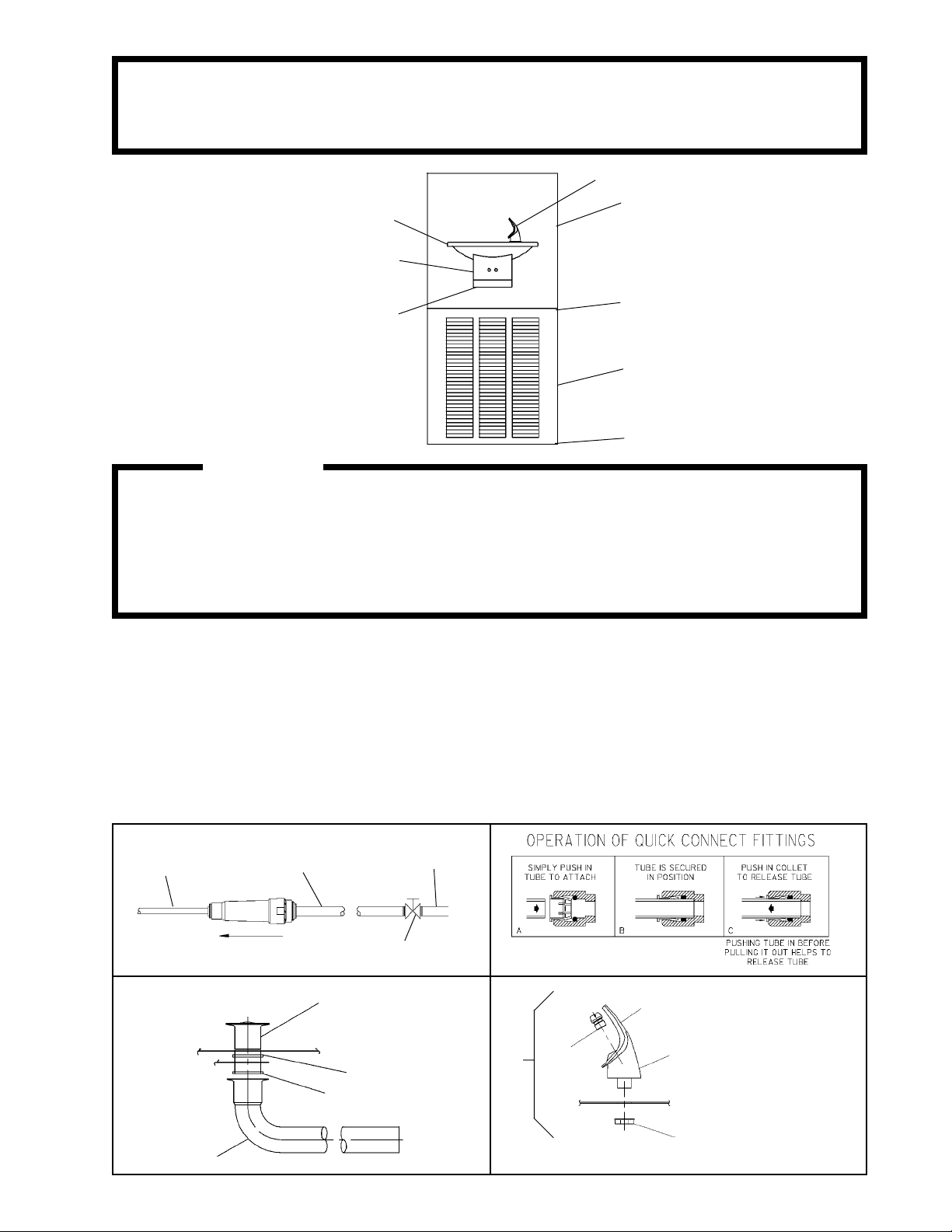
1/4" O.D. TUBE
WATER INLET
TO COOLER
FIG. 1
3/8" O.D. UNPLATED
COPPER TUBE CONNECT
COLD WATER SUPPLY
NOTE: WATER FLOW
DIRECTION
SERVICE STOP
(NOT FURNISHED)
21
BASIN
22
23
BUILDING WATER
INLET
FIG. 2
1
3
NOTE: WHEN INSTALLING
2
REPLACEMENT BUBBLER
AND PEDESTAL, TIGHTEN
4
NUT (ITEM 5 ) ONLY TO HOLD
PARTS SNUG IN POSITION.
DO NOT OVER TIGHTEN.
FIG. 3
26
5
FIG. 4
97867C (REV. B - 8/04)
Page 2
ENOA8C*A
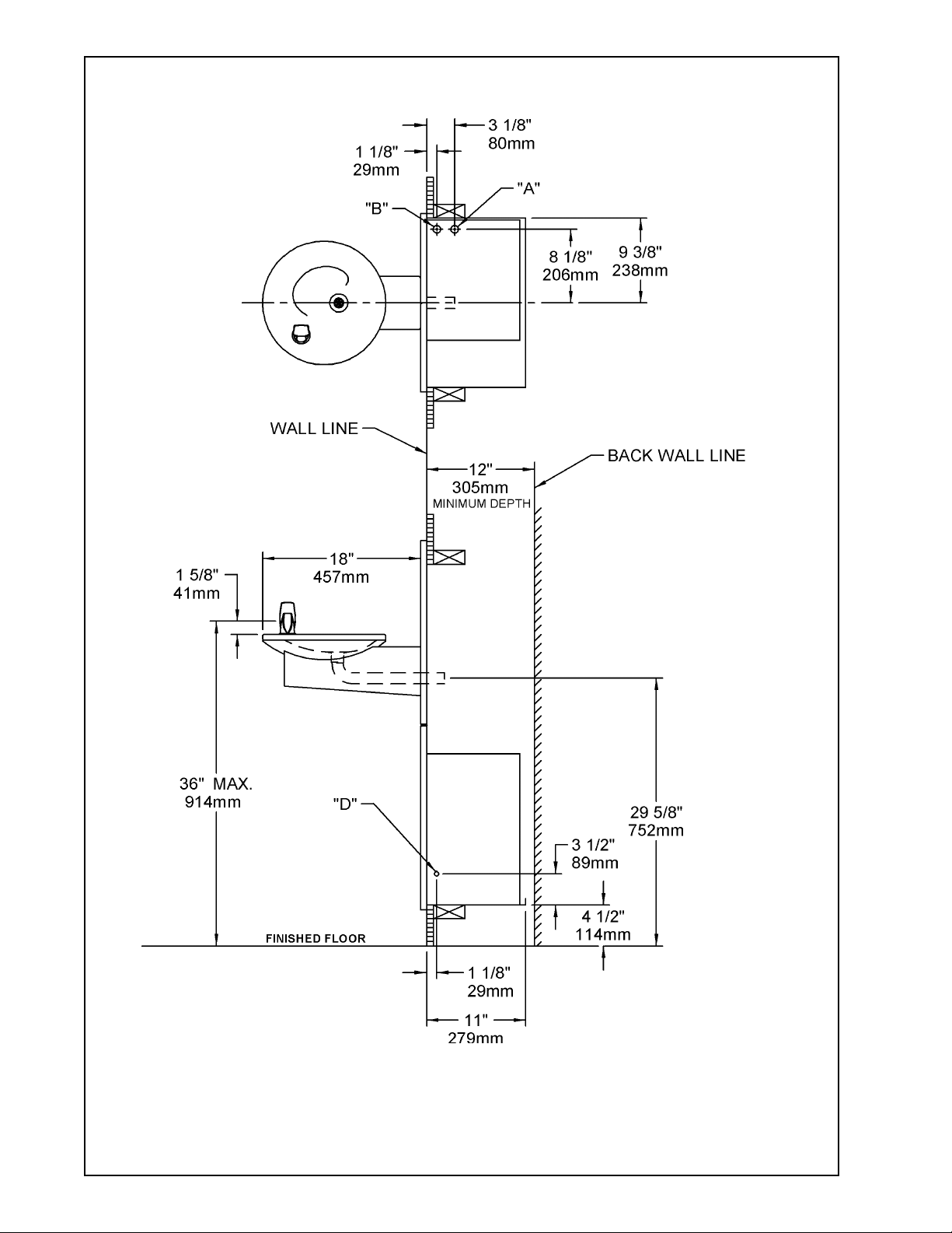
MODEL ENOA8C
LEGEND
A = 1/4" O.D. TUBE CONNECT (CHILLER WATER OUTLET)
B = 3/8" O.D. TUBE CONNECT (CHILLER WATER INLET) SHUT OFF VALVE BY OTHERS
C = 1-1/4" TRAP NOT FURNISHED
D = ELECTRICAL INLET
97867C (REV. B - 8/04)
FIG. 5
PAGE 2
Page 3

ENOA8C*A
INSTALLATION INSTRUCTIONS
1. Install remote chiller. Remove front panel of chiller. Remove and discard cardboard inner pack from between compressor and
side panel. Slide chiller onto the shelf and position it to the left side of shelf. (See Figure 5)
NOTE: Building construction must allow for adequate air flow on both sides, top, and back of chiller. See chiller instructions for
additional instructions.
2. Make water supply connections. Install a shut-off valve and union connection to building water supply (valve and union not
provided). Turn on the water supply and flush the line thoroughly.
3. ENOA MODELS: Make connection between remote chiller and building supply line. Inlet port is marked on the chiller (1/4" O.D.
copper tube). Bend the copper tube (provided) at an appropriate length from chiller to opening in frame. Install the in-line strainer
(provided with chiller) by pushing it in until it reachs a positive stop, approximately 3/4" (19mm) on the marked chiller inlet port.
Connect building supply line to strainer. DO NOT SOLDER TUBES INSERTED INTO THE STRAINER AS DAMAGE TO THE
O-RINGS MAY RESULT. (See Figure 6)
4. Hang the upper panel on the mounting frame hanger. Align holes in the panel with the holes in the mounting frame. Be sure that
panel is engaged with hanger at top of frame before releasing it.
5. Install the fountain. Remove access cover plate on underside of fountains and save the screws. Mount the fountain to the
upper panel and the wall frame with (4) 5/16" x 1 3/4" (44mm) long bolts and nuts (provided). Install spacers on bottom two
bolts. Tighten securely.
6. Attach waste tube (1 1/4" OD) to 1 1/4" OD slip trap (provided by others).
7. ENOA MODELS: Make connections between remote chiller outlet tube and fountain. Outlet port is marked on the chiller
(1/4" O.D. copper tube). Install a 1/4" x 1/4" union (provided) on the marked chiller outlet port. Insert the 1/4" poly tubing coming
from the fountain into the union. Turn on water supply and check for leaks. DO NOT SOLDER TUBES INSERTED INTO THE
UNION AS DAMAGE TO THE O-RINGS MAY RESULT. (See Figure 6).
8. These products are designed to operate on 20-105 PSIG supply line pressure. If inlet pressure is above 105 PSIG, a pressure
regulator must be installed in the supply line. Any damage caused by reason of connecting these products to supply line
pressures lower than 20 PSIG or higher than 105 PSIG is not covered by warranty.
9. Make electrical connections to the chiller. See chiller instructions.
10. Check stream height from bubbler. Stream height is factory set at 35 PSI. If supply pressure varies greatly from this, turn
adjustment screw on regulator (Item 9). Clockwise adjustment will raise stream height and counter-clockwise
will lower stream height. For best adjustment stream should hit basin approximately 6 1/2" from the bubbler.
11. Mount lower panel. Loosen the (2) #10-24 x 5/8" (16mm) screws at frame bottom lip. Slide upper tongue of lower panel under
lower edge of already installed upper panel. Tighten previously loosened screws securely.
12. Replace bottom access panel to fountain basin using screws provided. Tighten securely.
28
CHILLER
OUTLET
ENOA8C TUBE ROUTING
6 - TO
BUBBLER
6
30
SEE FIG. 4
37
6
SEE FIG. 3
CHILLER
INLET
25, 27, 29
SEE FIG. 9
FIG. 6
FIG. 7
PAGE 3
97867C (REV. B - 8/04)
Page 4

1
2
3
4
5
6
7
8
9
10
11
12
13
14
15
16
17
18
19
20
21
22
23
24
25
26
27
28
29
30
31
32
33
34
35
36
37
NS
NS
NS
PART NO.ITEM NO.
56073C
40322C
56011C
55997C
75580C
56092C
56082C
40045C
61313C
50986C
22525C
50203C
70208C
31376C
75507C
31272C
38417001
22526C
70256C
70016C
45336C
50074C
50377C
31384C
21846C
45330C
70055C
70683C
22535C
55996C
51409C
70817C
38417001
28183C
111008343890
26833C
55001026
70199C
70020C
74080053
PARTS LIST
DESCRIPTION
Bubbler Assembly
Orifice Assembly
Housing Assembly
Pedestal
Bubbler Locknut
Poly Tubing (Cut To Length)
Retaining Nut
Hex Nut
Regulator
Holder-Regulator
Regulator Mounting Bracket
Strain Relief
Screw - #10-24 X .37 PHTC
Power Cord
Fitting - 1/4 NPTF X 1/4 O.D.
Solenoid Valve Assembly
Screw - #8-18 x .37 HHSM
Solenoid Mounting Bracket
Screw - 1/4-20 x .38 HHTC
Hex Nut #10-32
Strainer & Ferrule Assembly
Gasket - Tailpipe
Gasket - Tailpipe
Sensor - Clear
Cover Plate
Waste Arm
Speed Nut
Union - 1/4
Fountain Body & Shell
Strainer
Spacer - 1/2 X .44
Elbow - 1/4 X 1/4
Screw - #8-18 X .37 HHSM
Back Panel
Screw - #10-24 x .62 HHMS
Lower Panel
Basin - Swirlflow
Bolt - 5/16-18 x 1.75 Lg
Nut - Hex 5/16-18
Spacer
ENOA8C*A
TROUBLE SHOOTING AND MAINTENANCE
1. Orifice Assy: Minerals deposits on orifice can cause water flow to
spurt or not regulate. Mineral deposits may be removed
from the orifice with a small round file not over 1/8" diameter or a
small diameter wire. CAUTION: Do not file or cut orifice materials.
2. Stream Regulator: If orifice is free of material deposits regulate
water flow according to instructions on page 3.
3. Sensor Control: The sensor has a 2 second delay time. If sensor
fails to operate valve mechanism or operates erratically, check
the following:
a) Ensure there are no obstructions within a 40 inch radius from
the front of fountain.
b) Check wire connections at the solenoid valve and at the sensor.
CAUTION: Make sure unit is unplugged before checking any
wiring.
c) Ensure proper operation of solenoid valve. If there is an audible
clicking sound yet no water flows, look for an obstruction in the
valve itself or elsewhere in the water supply line.
WARNING: Do not expose sensor to direct sunlight.
4. Sensor Range Adjustment: The electronic sensor used in this
fountain is factory pre-set for a "visual" range of 36 inches. If
actual range varies greatly from this, or a different setting is desired,
follow the range adjustment procedure below:
a) Remove bottom cover of fountain.
b) Remove sensor by removing washers and nuts that secure
sensor on studs.
c) Locate range adjustment screw between the red lenses of the
sensor, then with a small tip screwdriver, rotate the range adjust ing screw clockwise to increase range or counter-clockwise to
decrease range. 1/4 turn of screw is equal to approximately
12 - 18 inches of range.
CAUTION: Complete range of sensor (24 - 46 inches) is only one
turn of the adjusting screw.
d) Remount sensor on studs and replace bottom cover.
6
6
10
11
12
14
15
16
17
16
33
FIG. 8
97867C (REV. B - 8/04)
8
9
7
13
32
31
FIG. 9
REPAIR SERVICE INFORMATION TOLL FREE NUMBER 1.800.260.6640
ELKAY MANUFACTURING COMPANY 2222 CAMDEN COURT OAK BROOK, IL 60523 630.574.8484
FOR PARTS, CONTACT YOUR LOCAL DISTRIBUTOR OR CALL 1.800.323.0620
PAGE 4
18
19
6
20
24
 Loading...