

Page 1
ENLZS8WS_1G
Enhanced
INSTALLATION & USE MANUAL
™
LZ
Series Bottle Filling Stations & Coolers
Page 1 1000004538 (Rev. C - 07/19)
Page 2
ENLZS8WS_1G
3"
2"
19"
483mm
3 1/2"
90mm
19"
482mm
HANGER
BRACKET
51mm
8 1/16"
205mm
76mm
5 7/8"
149mm
C
FILTER
WATER
12 1/2"
318mm
ADA
27"
686mm
RIM
31 5/16"
796mm
HEIGHT
REQUIREMENT
32 7/8"
835mm
HEIGHT
ORIFICE
2 7/8"
73mm
2"
15"
7/16" X 3/4" (11mm X 19mm)
OBROUND HOLES (6)
7"
178mm
L
18"
458mm
7"
178mm
C
381mm
6 3/8"
162mm
6 3/8"
162mm
SENSOR
ACTIVATION
51 9/16"
1310mm
HOLES (9)
O 9/32" (7mm)
51mm
E
E
2"
51mm
B
FILTER
38 1/2"
979mm
28 13/16"
731mm
A
D
21 7/8"
556mm
28 13/16"
731mm
13 15/16"
354mm
3 7/8"
98mm
2"
51mm
5 3/4"
146mm
F
17 7/16"
443mm
19"
483mm
FINISHED FLOOR
7"
178mm
7"
178mm
PISO ACABADO SOL FINI
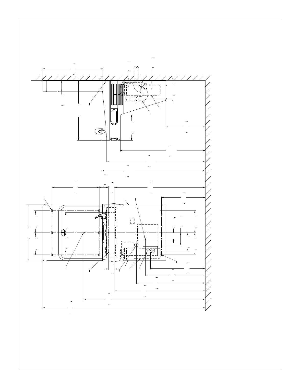
REDUCE HEIGHT BY 3 INCHES FOR INSTALLATION OF CHILDREN’S ADA COOLER
OTHERS) 3 IN. (76mm) MAXIMUM OUT FROM WALL
C = 1-1/4" TRAP NOT FURNISHED
F = 7/16 BOLT HOLES FOR FASTENING UNIT TO WALL
**NEW INSTALLATIONS MUST USE GROUND FAULT CIRCUIT INTERRUPTER (GFCI)
NOTE: IT IS HIGHLY RECOMMENDED THAT THE CIRCUIT BE DEDICATED AND THE LOAD PROTECTION BE SIZED FOR
LEGEND/LEYENDA/LÉGENDE
A = RECOMMENDED WATER SUPPLY LOCATION 3/8 O.D. UNPLATED COPPER TUBE CONNECT STUB WITH SHUT OFF (BY
B = RECOMMENDED LOCATION FOR WASTE OUTLET 1-1/4" O.D. DRAIN STUB 2 IN. OUT FROM WALL
D = ELECTRICAL SUPPLY (3) WIRE RECESSED BOX DUPLEX OUTLET**
E = INSURE PROPER VENTILATION BY MAINTAINING 6” (152 mm) (MIN.) CLEARANCE FROM CABINET LOUVERS TO WALL.
20 AMPS.
1000004538 (Rev. C - 07/19)
Fig. 1
Page 2
Page 3
ENLZS8WS_1G
HANGER BRACKET INSTALLATION
1) Remove hanger bracket fastened to back of cooler by removing one (1) screw
2) Mount the hanger bracket as shown in Figure 1 (Pg. 2)
NOTE: Hanger Bracket MUST be supported securely. Add xture support carrier if wall will not provide adequate support. Anchor hanger securely to wall using all six
(6) 1/4 in. dia. mounting holes.
IMPORTANT: 5-7/8 in. (150mm) dimension from wall to centerline of trap must be maintained for proper t.
INSTALLATION OF COOLER
3) Hang the cooler on the hanger bracket. Be certain hanger bracket is engaged properly in the slots on the cooler back as shown in Figure 1 (Pg. 2).
4) Remove the four (4) screws holding the lower front panel at the bottom of the cooler (See Fig 7, Pg.5). Remove the front panel by pulling straight down and set aside.
5) Secure cooler frame to wall by installing (2) screws and washers (not supplied). (See Fig. 2, Pg. 4). Make sure the screws engage in a structural member.
6) Connect the supply water to the lter inlet tube.
7) Install trap. Remove the slip nut and gasket from the trap and install them on the cooler waste line making sure that the end of the waste line ts into the trap. Assemble the slip nut
and gasket to the trap and tighten securely.
IMPORTANT: If it is necessary to cut the drain, loosen the screw at the black rubber boot and remove tube, check for leaks after re-assembly.
BOTTLE FILLER INSTALLATION
8) Remove two (2) mounting screws with 5/32" Allen wrench holding bottle ller to wall mounting plate (See Fig.8, Pg. 5). Note do not discard mounting screws, they will be
needed to secure bottle ller to wall mounting plate.
9) Remove wall mounting plate from Bottle Filler (see Fig 8, Pg. 5). Place wall mounting plate against wall on top of basin. Center the wall mounting plate side to side with the basin. Mark the
six (6) mounting holes with a pencil. Place tape over wiring harnes conection on top of cooler to prevent debris from falling into Connection.
10) Remove wall mounting plate from wall. NOTE: Mounting plate MUST be supported securely. Add xture support carrier if wall will not provide adequate support.
11) Install wall mounting plate to wall using six (6) 7/16" obround mounting holes (mounting bolts not included) (See Fig.8, Pg. 5). Use appropriate fasteners for your wall type.
12) Install gasket on bottom of bottle ller tower with gasket support bracket & (2) screws. (See Fig. 4., Pg. 5)
13) Route 3/8” tubing through the opening in the bottle ller gasket and plug into bulkhead tting in basin. Route the wiring harness through the
gasket and plug into the connector on the top of the basin.
14) Place bottle ller on four (4) hooks on the mounting plate installed on wall. Make sure round boss in gasket ts in hole of basin. (See Fig. 8, Pg. 5).
15) Plug electrical cord into outlet on wall.
16) Remove lter from carton, remove protective cap, attach lter to lter head by rmly inserting into head and rotating lter clockwise. Ensure that blue label can be read when
lter is installed. (Fig. 12, Pg. 7.)
17) Turn water supply on and inspect for leaks. In both cooler and bottle ller. Fix all leaks before continuing.
18) Once cooler and bottle lter has been inspected for leaks and any leaks found corrected.
19) Reinstall two mounting screws from rst step (See Fig. 8, Pg. 5). Caution, do not over tighten screws.
20) Once power is applied to the cooler the GREEN LED light will illuminate on the bottle ller showing good lter status along with the LCD Bottle Counter.
21) Verify proper dispensing by placing cup, hand, or any opaque object in front of sensor area and verify water dispenses. Note: the rst initial dispenses might have air in line
which may cause a sputter. This will be eliminated once all air is purged from the line.
22) Once unit tests out, install Lower Panel back on water cooler(s). Units are now ready for use.
Instructions For Replacing Filters
1) Remove lower cover on cooler by removing (4) screws (See Fig.7, Pg. 5).
2) Turn off water supply; dispense water to relieve pressure.
3) Remove power by unplugging cooler.
4) Turn used lter counterclockwise 1/4 turn to remove from lter head.
5) Remove cap from new lter and use to seal used lter.
6) Insert new lter into existing lter head and turn fully clockwise. Make sure you can read the label on the front of the lter once it is installed. (See Fig.12 on Pg. 7).
7) Plug in unit to restore power.
8) Turn on water supply and run a minimum of two gallons of water through the lter to purge air any ne carbon particles from lter. Also run water through bottle ller
Note: Filter status light will automatically reset once new lter is installed.
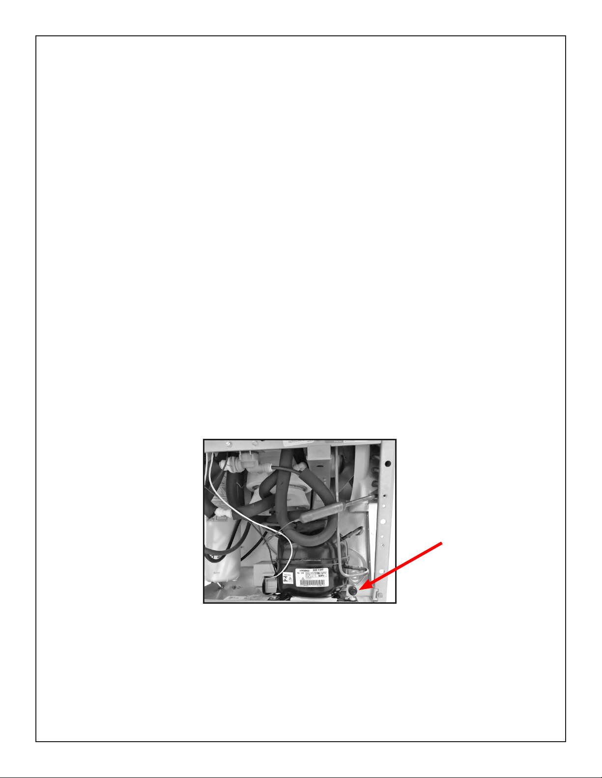
Programming Button
FIG. A
Instructions To Access Programming Button
1) Remove lower cover on refrigerated unit by removing (4) screws (See Fig 7, Page 5.
2) Button is located in lower right corner of unit (See Fig. A, Pg. 3).
Page 3 1000004538 (Rev. C - 07/19)
Page 4
ENLZS8WS_1G
Secure cooler frame to wall by installing (2) screws and washers (not supplied).
FIG. 2
Lay gasket along back of bottle ller mounting plate. Align BF and lay on cooler basin.
FIG. 3
Fig. 4
1000004538 (Rev. C - 07/19)
Attach the 3/8 water line into the bulkhead tting.
(Gasket removed from bottle ller for clarity)
Fig. 5
Page 4
Page 5

ENLZS8WS_1G
Fig. 7
Connect the bottle ller electrical harness.
(Gasket removed from bottle ller for clarity)
Fig. 6
MOUNTING BOLT HOLES (6)
WALL MOUNTING PLATE
32
31
33
BOTTLE FILLING UNIT
Fig. 8
Page 5 1000004538 (Rev. C - 07/19)
Page 6

OPERATION OF QUICK CONNECT FITTINGS
33
ENLZS8WS_1G
115V Refrigerated Wiring Diagram
with Alpha/Numeric Display
34
31
28
25
36
35
27
Fig. 9
Superseal Fitting Assembly
Note: Screw the locknut hand tight to seal
Fig. 10
1000004538 (Rev. C - 07/19)
Page 6
OPERATION OF QUICK CONNECT FITTINGS
SIMPLY PUSH IN
SIMPLY PUSH IN
TUBE TO ATTACH
TUBE TO ATTACH
A
A
TUBE IS SECURED
TUBE IS SECURED
IN POSITION
IN POSITION
B C
B CA
PUSH IN COLLET
PUSH IN COLLET
TO RELEASE TUBE
TO RELEASE TUBE
Fig. 11
Page 7

ENLZS8WS_1G
11
Basin
Locknut
BUBBLER DETAIL
Filter Label
Location
Back of Filter
Fig. 12
NOTE:
Fig. 13
When installing replacement bubbler and pedestal, tighten nut only to hold parts
snug in position. Do Not Overtighten.
3
2
1
Fig. 14
WATERSENTRY® Filter Detail
WATERSENTRY® FILTER PARTS LIST
DESCRIPTIONITEM NO. PART NO.
1
2
3
51300C
1000005214
1000004409
Filter Assy - 3000 Gal.
Kit - Filter Head Fittings includes
John Guest Fittings & 3/8" Elbow
Filter Bracket/Screws
Kit - NFC Board/Cover
Page 7 1000004538 (Rev. C - 07/19)
Page 8

ENLZS8WS_1G
Service Instructions
Lower and Upper Shroud
To access the refrigeration system and plumbing connections, remove four screws from bottom
of cooler to remove the lower shroud. To remove the upper shroud for access to the pushbars,
regulator, solenoid valve or other components located in the top of the unit, remove lower shroud,
disconnect drain, remove four screws from tabs along lower edge of upper shroud, unplug two
wires and water tube.
Bubbler
To remove the bubbler, rst disconnect the power supply. The underside of the bubbler can be
reached through the access panel on the underside of the upper shroud. Remove the access
panel by removing the retaining screw. To remove the bubbler, loosen locknut from the underside
of the bubbler and remove the tubing from the quick connect tting per the Operation Of Quick
Connect Fittings section in the General Instructions. After servicing, replace the access panel
and retaining screw.
Switches Behind the Push Bar
The regulator in an EZ cooler is always held fully open by the use of a single regulator nut (See
Item 9, Fig. 15). Water is not dispensed until the pushbar is depressed to activate a switch which
then opens a solenoid valve.
To remove sidebars, from the inside compress the ared tabs and pull out carefully. To reinstall
side pushbars, the front of the pushbar is inserted rst. While keeping the switch depressed,
snap the rear of the pushbar into position.
11
Fig. 15
22
2
11
22
Cleaning
Stainless Steel
• General cleaning: use an ordinary mild detergent and soft cloth, rinse and towel dry.
• Steel soap pads should never be used; particles can adhere to a stainless steel basin
surface and will eventually rust.
• Light scratches are normal for stainless steel basins; over time they will blend into the
uniform nish pattern.
Plastic Components
• General cleaning: use an ordinary mild detergent and soft cloth, rinse and towel dry.
• Wiping the surface clean to remove debris or build up will not hurt the antimicrobial
properties.
Temperature Control
• Factory set at 50°F (+/- 5°F) under normal conditions. For temperature adjustments, refer to
sticker on left side of top bar.
Stream Height Adjustment
VIEW OF UNDERSIDE OF BASIN SHROUD
Stream Height Adjustment Location
19
6
12, 13
REGULATOR
ASSEMBLY
SNAP
8
9
12
ALIGNMENT
NOTCH
SNAP
ALIGNMENT
PEG
1000004538 (Rev. C - 07/19)
Fig. 15
Page 8
Page 9

ENLZS8WS_1G
Returns to Main Menu
Notes End Action
action
Action Sub Menu/
action
Returns to Main Menu
Returns to Main Menu
turned off
to lter, LED status display, lter error capability
Drops to next level when selected
Returns to Main Menu
Refrigeration on Returns to Main Menu
bottle needs to be to activate
Drops to next level when selected
and night light
Momentary Select time on 24 hours – 1-12AM and 1-12PM Drops to next level when selected
Momentary Select time off 24 hours – 1-12AM and 1-12PM Drops to next level when selected
Momentary Select time on 24 hours – 1-12AM and 1-12PM Drops to next level when selected
Select Weekday Drops to next level when selected
Select Weekend Drops to next level when selected
Momentary Select time off 24 hours – 1-12AM and 1-12PM Returns to Main Menu
Programming Instruction
Depress Button for 3 seconds to activate main menu - release
Cycles thru main menu items 2 seconds each for 2 cycles then exits menu unless selected
Cycles thru sub menu items 2 seconds each for 2 cycles then returns to main menu unless selected
Selections are saved when the menu is exited
Top level Action Sub Menu 1 Action Sub Menu/action Action Sub Menu/
on unit
Info Momentary Scrolls through all the settings
Day (Sunday-Saturday Momentary Use push button to select the day on the display Drops to next level when selected
AM/PM Momentary Use push button to select AM or PM Drops to next level when selected
Info Momentary Flashes error code Returns to Main Menu
Set time Momentary Drops to next level when selected
Hour (12 hour) Momentary Use push button to select Hour Drops to next level when selected
Min 0-69 in 5 minute increments Momentary Use push button to select closest minute Returns to Main Menu
No Momentary Turn off lter status and erros No Filter unit - Error codes related to lter status
Yes Momentary Default setting - Turn on lter status and errors Filter status has default ON / Default has read write
Filter Momentary Drops to next level when selected
1.1gpm
No Momentary Turns off power to E/S relay sets bottle ll time to 1.5gpm Refrigeration off Returns to Main Menu
Yes Momentary Default setting - Turns on power to E/S relay - sets time to
Refrig Momentary Drops to next level when selected
to be before turning before turning on or off the bottle ller
1-10 Momentary Default setting 5 - Adjusts distance from sensor the bottle needs
Range Momentary The lower the number, the closer to the sensor the
25% Momentary Returns to Main Menu
50% Momentary Returns to Main Menu
B-Light Momentary The settings are for the brightness of the display
75% Momentary Default Setting Returns to Main Menu
100% Momentary Returns to Main Menu
EnerSave Momentary Drops to next level when selected
Off Momentary Default Setting Returns to Main Menu
On Momentary Set Energy Save Schedule Drops to next level when selected
Page 9 1000004538 (Rev. C - 07/19)
Page 10

ENLZS8WS_1G
Enhanced EZH2O Error Codes
Error
Code
E013 Missing or Incomplatible Filter • Check that lter is installed correctly (label facing forward, white tag fac-
E013 &
E014
Error Description Corrective Action
Bottle ller area obstructed • Remove obstruction.
• Clean lens on IR sensor
• Unplug unit for at least 30 seconds and restart
• If error repeats, replace IR sensor
ing back)
• Unplug unit for at least 30 seconds and restart
• Replace lter
• Replace lter head assembly with repair kit
• If error repeats, contact certied service professional
Missing NFC Board • Unplug unit for at least 30 seconds and restart
• Verify cable connector is plugged into NFC board on lter head assembly
• Replace lter head assembly with repair kit
• If error repeats, contact certied service professional
1000004538 (Rev. C - 07/19)
Page 10
Page 11

ENLZS8WS_1G
Pictured is unit only without bottle ller.
Note: Danger! Electrical shock hazard. Disconnect power before serviceing unit.
Uses HFC-134A refrigerant
Filter Location
14
1
8
6
21
15
23
9
26
5
See Fig. 15
12
19
29
10
18
12 or 13
30
See Fig. 15
3
2
12
16
21, 24
7
19
20
17
4
19
Fig. 18
Page 11 1000004538 (Rev. C - 07/19)
Page 12

ENLZS8WS_1G
ITEM
NO.
1
2
0000001337
3
*4
5
6
7
8
1000001877
9
1000004564
10
1000004572
11
12
13
1000001600
14
1000004568
15
16
17
18
19
20
0000000238
21
22
1000001812
23
24
1000001602
25
1000004559
26
27
1000004547
28
1000004550
29
NS
NS
NS = Not Shown
PART
NO.
28401C
36216C
36322C
56092C
56229C
66703C
56073C
98734C
98775C
98776C
98777C
98778C
98898C
98724C
56237C
56213C
98773C
27416C
27413C
115V PARTS LIST
DESCRIPTION
Hanger Bracket
Basin - Stainless Steel
Wiring - Front/Side Push Bar
Compr - Service Pak 115V EMIS70HHR
Tube - Poly (72”)
Assy - Shroud - Upper (Front Side Push)
Drier
Kit - Drain Replacement (Bottle Filler) (Bracket, Tube, Fitting, Clamp)
Kit - Regular/Holder/Nut
Kit - Solenoid Valve/Regulator Assembly
Kit - Flexi Bubbler/“O”-Ring/Nut
Kit - Pushbar (Front/Side) EZS TL
Kit - Pushbar (Front Only)
Power Cord
Kit - Fan Motor/Blade/Screws/Nut
Kit - Condenser/Drier/Wire Ties
Kit - Compr Mtg Hdwe/Grommets/Clips/Studs
Kit - Heatx/Drier
Kit - Hardware
Kit - 115V Electricals (Relay, Overload, Cover)
Kit - Evap. Replacement
Kit - Bottle Filler Drain
Shroud
Kit - 75583C Elbow 5/16" x 1/4" (3 Pack)
Wire Assy - Jumper
Access Panel
Harness - Cooler
Wire - 6” Jumper
Kit - Cold Control
Wrapper Stainless Steel
Wrapper Light Grey
*INCLUDES RELAY & OVERLOAD. IF
UNDER WARRANTY, REPLACE WITH SAME
COMPRESSOR USED IN ORIGINAL ASSEMBLY.
NOTE: All correspondence pertaining to any of the
above water coolers or orders for repair parts MUST
include Model No. and Serial No. of cooler, name and
part number of replacement part.
ATTENTION:
If the product serial number is before 190424189, please refer to archived
documents section of Elkay.com for the most accurate parts list.
(www.elkay.com/archived-documents)
BOTTLE FILLER
REPLACEMENT PART KITS
ITEM
PART NO. DESCRIPTION
NO.
NS
98546C
30
98549C
31
1000004573
NS
1000005077
32
1000002433
33
1000005219
34
1000004544
NS
1000004436
35
1000004546
36
1000004549
NS = Not Shown
FCC COMPLIANCE STATEMENT
CAUTION: Changes or modications not expressly approved could void your authority to use this equipment
This device complies with Part 15 of the FCC Rules. Operation to the following two conditions: (1) This device may not cause harmful interference, and (2) this device must
accept any interference received, including interference that may cause undesired operation
INDUSTRY CANADA STATEMENT
This device complies with Industry Canada license-exempt RSS standard(s). Operation is subject to the following two conditions: (1) this device may not cause interference,
and (2) this device must accept any interference, including interference that may cause undesired operation of the device.
Le présent appareil est conforme aux CNR d’Industrie Canada applicables aux appareils radio exempts de license. L’exploitation est autorisée aux deux conditions
suivantes : (1) l’appareil ne doit pas produire de brouillage, et (2) l’utilisateur de l’appareil doit accepter tout brouillage radioélectrique subi, même si le brouillage est
susceptible d’en compromettre le fonctionnement.
Kit - Aerator Replacement
Kit - Hardware & Waterway (BF)
Kit - Solenoid 120V (BF)
Nameplate - Elkay Filtered
Kit - Top Cover Assy (BF)
Kit - IR Sensor K+
Kit - Alpha Numeric LED Board
Kit - Tower/Basin Gasket
Harness - Bottle Filler
Harness - LED/IR Board
PRINTED IN U.S.A.
ELKAY MANUFACTURING COMPANY • 2222 CAMDEN COURT • OAK BROOK, IL 60523 • 630.574.8484 • www.elkay.com
1000004538 (Rev. C - 07/19)
FOR PARTS, CONTACT YOUR LOCAL DISTRIBUTOR OR CALL 1.800.834.4816
REPAIR SERVICE INFORMATION TOLL FREE NUMBER 1.800.260.6640
Page 12
 Loading...