

EMASMB*A & LMASMB*A
INSTALLATION, CARE & USE MANUAL
EMASMB & LMASMB Surface Mount Bottle Filling Stations
IMPORTANT
FOR INDOOR USE ONLY!
ALL SERVICE TO BE PERFORMED BY AN
AUTHORIZED SERVICE PERSONNEL.
RATED FOR COMMERCIAL USE ONLY
TOOLS/ITEMS REQUIRED
BUT NOT SUPPLIED
- SERVICE STOP VALVE WITH 3/8"
COMPRESSION OUTLET
- FASTENERS FOR WALL TYPE (5 REQ’D.)
- SLIP JOINT DRAIN UNION OR
COMPRESSION CLAMP
- 5/32" HEX-WRENCH
Installer
To assure you install this model easily and correctly, PLEASE READ THESE
SIMPLE INSTRUCTIONS BEFORE STARTING THE INSTALLATION.
CHECK YOUR INSTALLATION FOR COMPLIANCE WITH ALL PLUMBING, ELECTRICAL AND OTHER APPLICABLE CODES. FOLLOW ALL
WARNINGS AND CAUTIONS CAREFULLY. After installation, leave these
instructions with the customer for future reference.
Warnings
1. Use with clean, clear, fresh potable drinking water only! Do not use with water that is microbiologically
unsafe or of unknown quality without adequate disinfection before the system.
2. These products are designed to operate on 20 to 105 psi (0.14-0.72 MPa) supply line pressure and a
maximum water temperature of 90°F (32°C). If inlet pressure is above 105 psi (0.72 MPa), a pressure
regulator must be installed in supply line. Any damage caused by reason of connecting this product to
supply line pressure lower than 20 psi or higher than 105 psi is not covered by warranty.
This appliance can be used by children aged from 8 years and above and persons with reduced physical, sensory or
mental capabilities or lack of experience and knowledge if they have been given supervision or instruction concerning use
of the appliance in a safe way and understand the hazards involved. Children shall not play with the appliance. Cleaning
and user maintenance shall not be made by children without supervision.
Page 1
1000002042 (Rev.E - 07/16
EMASMB*A & LMASMB*A
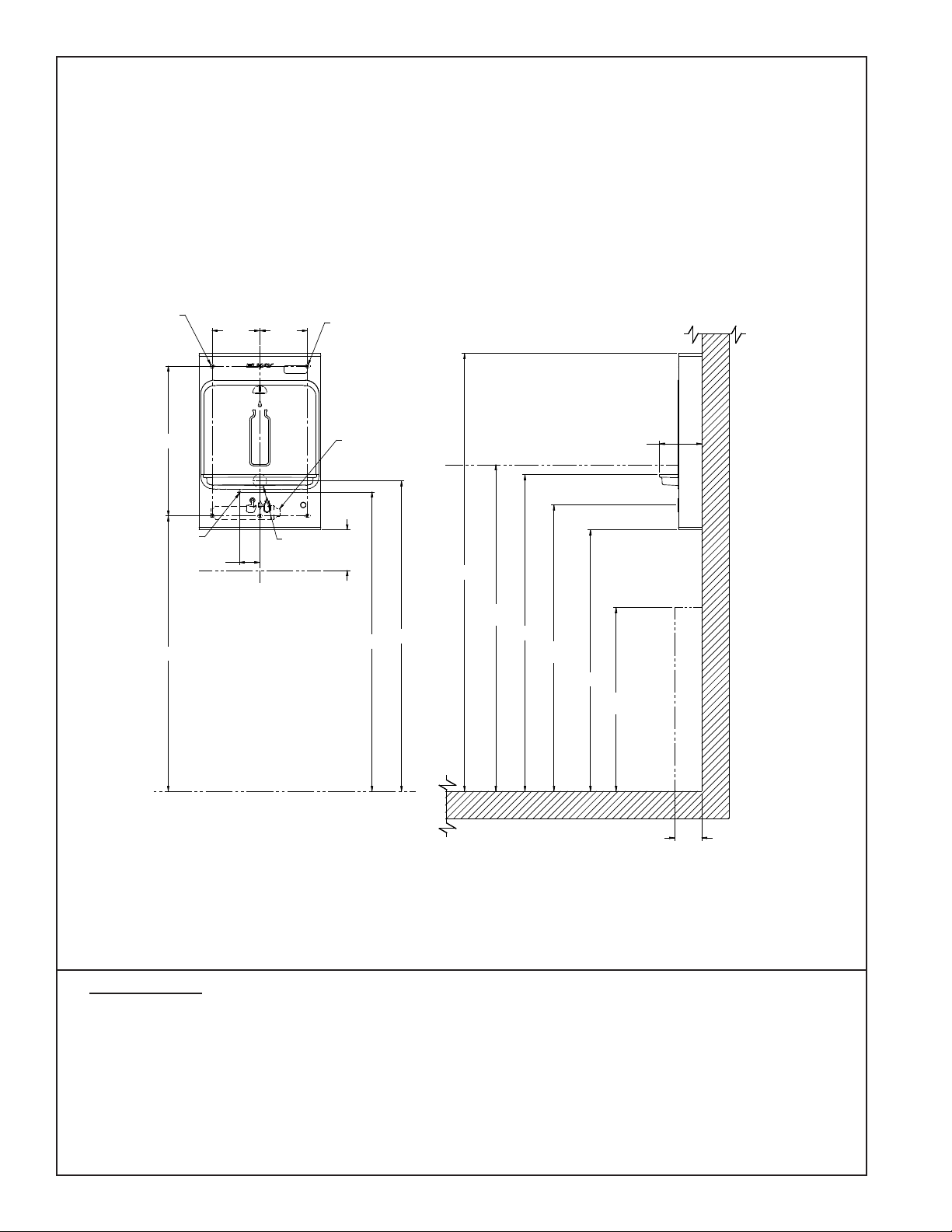
ROUGH-IN
EMASMB & LMASMB
ADA STAND ALONE MOUNTING
STAND ALONE MOUNTING
IMPORTANT!
INSTALLATION NOTES:
• Ensure wall is structurally sound to bear the loads imparted by the Surface Mount Bottle Filler.
• Ambient air temperature limits: 10°C - 38°C (50°F - 100.4°F). Climate Class SN-ST.
• Not suitable for installation in areas where water jets could be used.
7/16 X 3/4
11mm X 19mm
OBROUND
MOUNTING
HOLE (6)
"C"
22
559mm
40 1/2
1029mm
3/8"
9.5mm
WATER
INLET
"A"
3
76mm
7
178mm
3/8
(6)
O
1-1/4"
DRAIN
"B"
8mm
MOUNTING BOLT
FILTER USED ONLY
IN LMASMB UNITS
6
152mm
MINIMUM
CLEARANCE
1118mm
6 1/4
159mm
64 3/8
1635mm
48
1219mm
ADA HEIGHT
45 5/8
44
1159mm
46 1/2
1182mm
42 1/8
1069mm
‰ OF BUTTON
38 1/2
977mm
27
686mm
ADA HEIGHT
7
178mm
‰
31.7mm
FINISHED FLOOR
FINISHED FLOOR
4
102mm
ADA DEPTH
FIGURE 1
LEGEND:
A = RECOMMENDED WATER SUPPLY LOCATION; 1/2" IPS MAXIMUM PIPE SIZE. SERVICE STOP VALVE NOT FURNISHED.
B = RECOMMENDED WASTE LOCATION. WASTE SHOWN IN WALL BUT MAY BE BEHIND WALL.
OUTLET 1-1/4” O.D. (TRAP NOT FURNISHED)
C =7/16" X 3/4" OBROUND MOUNTING HOLES FOR FASTENING BACKPLATE TO WALL.
Pre-Installation (reference Rough-Ins, Fig. 1 and Fig. 2)
1. Ensure Wall is structurally sound to bear the loads imparted by the EMASMB or LMASMB Bottle Filler
(On-Wall Bottle Filler). If necessary, install a Wall Support Carrier (not supplied).
2. Ensure Water Supply Line and Drain Line are sized and located as specied the Rough-in diagram.
3. Attach Service Stop Valve (not supplied) to Water Supply line orienting the 3/8"O.D. female compression
outlet horizontally to the left. Purge water line and test for leakage. Correct any leakage.
1000002042 (Rev.E - 07/16)
Page 2

EMASMB*A & LMASMB*A
ROUGH-IN
EMASMB & LMASMB
ADA ABOVE COOLER MOUNTING
STAND ALONE MOUNTING
IMPORTANT!
INSTALLATION NOTES:
• Ensure wall is structurally sound to bear the loads imparted by the Surface Mount Bottle Filler.
• Ambient air temperature limits: 10°C - 38°C (50°F - 100.4°F). Climate Class SN-ST.
• Not suitable for installation in areas where water jets could be used.
7/16 X 3/4
11mm X 19mm
OBROUND
MOUNTING
HOLE (6)
"C"
25 7/8
658mm
22
559mm
40 1/2
1029mm
3/8"
9.5mm
WATER
INLET
"A"
7
178mm
76mm
17 7/8
454mm
3
7
178mm
‰
ADA HEIGHT
WATER COOLER
1-1/4"
31.7mm
DRAIN
"B"
8mm
MOUNTING
BOLT
FILTER USED ONLY
IN LMASMB UNITS
6
152mm
MINIMUM
CLEARANCE
3/8
O
44
1118mm
(6)
45 5/8
1159mm
64 3/8
1634mm
48
1219mm
ADA HEIGHT
46 1/2
1182mm
42 1/8
1069mm
‰ OF BUTTON
38 1/2
977mm
27
686mm
ADA
HEIGHT
6 1/4
159mm
FINISHED FLOOR
FINISHED FLOOR
4
102mm
ADA DEPTH
FIGURE 2
LEGEND:
A = RECOMMENDED WATER SUPPLY LOCATION; 1/2" IPS MAXIMUM PIPE SIZE. SERVICE STOP VALVE NOT FURNISHED.
B = RECOMMENDED WASTE LOCATION. WASTE SHOWN IN WALL BUT MAY BE BEHIND WALL.
OUTLET 1-1/4” O.D. (TRAP NOT FURNISHED)
C =7/16" X 3/4" OBROUND MOUNTING HOLES FOR FASTENING BACKPLATE TO WALL.
Pre-Installation (reference Rough-Ins, Fig. 1 and Fig. 2)
1. Ensure Wall is structurally sound to bear the loads imparted by the EMASMB or LMASMB Bottle Filler
(On-Wall Bottle Filler). If necessary, install a Wall Support Carrier (not supplied).
2. Ensure Water Supply Line and Drain Line are sized and located as specied the Rough-in diagram.
3. Attach Service Stop Valve (not supplied) to Water Supply line orienting the 3/8"O.D. female compression
outlet horizontally to the left. Purge water line and test for leakage. Correct any leakage.
Page 3
1000002042 (Rev.E - 07/16

EMASMB*A & LMASMB*A
INSTALLATION INSTRUCTIONS
EMASMB UNIT SHOWN
REGULATOR
ASSEMBLY
PLUMBING DIAGRAM
NON-FILTERED
INSTALLER TO SUPPLY:
SHUT OFF VALVE
TOP SCREWS
TOP COVER
OUTER
WRAPPER
BATTERY TRAY
BOTTOM COVER
BOTTOM SCREWS
BACK PANEL
REAR VIEW
Wall Mounting (reference Rough-Ins, Fig. 1 and Fig. 2)
1. Remove Top Cover from Bottle Filler by removing two (2) screws from bottom of unit. Use a 5/32" hex wrench
(not supplied).
2. Remove Bottom Cover from Bottle Filler by removing two (2) screws from bottom of unit. Use a 5/32" hex wrench
(not supplied).
3. With the Top and Bottom Covers removed, the Back panel is now free to be removed from Bottle Filler.
4.. Fasten Back Panel to structurally secure wall thru ve 7/16" obround holes with fasteners appropriate for wall type.
Locate Back Panel as specied in Rough-In. If necessary, attach to Wall Support Carrier (not supplied).
5. Ensure Back Panel is not obstructed by the roughed-in Water and Drain Lines. If Back Panel is prevented from
seating properly, reposition Water and/or Drain Lines slightly until the Bottom Cover ts easily.
6. Before hanging the On-Wall Bottle Filler, ensure the Insulated Waterline is routed inside of the Wrapper If outside
the Wrapper, reposition to inside or else the unit cannot be installed properly.
7. Hang the Bottle Filler onto the Back Panel, aligning two tabs onto the top of the Back Panel.
8. Secure Bottle Filler to Back Panel by replacing Top Cover on top of unit and fastening with two (2) supplied screws.
9. Replace the Bottom Cover on bottom of the unit and fasten in place with two (2) supplied screws.
Plumbing Connections
• Ensure lines and ports remain clean and free of contaminants during assembly.
• Purge each component if necessary.
• To ensure quick-connect connections seal properly, follow instructions per Figure 3.
Connect Plumbing Lines. NOTE: Connecting to water mains must be in compliance with local and national laws.
1. Connect water supply line to unit: NOTE: Hose-sets are not to be used for connecting to water mains.
2. Connect the 3/8"O.D. Copper tube from the in-line strainer to the 3/8" to the Service Stop Valve.
3. Connect the 1-1/4"O.D. Drain Tray Outlet to the in-wall Drain Line using a Slip Joint Drain Union or compression
clamp (not supplied). Tighten all connections water tight.
4. Turn water supply on, inspect for leaks and correct any leaks before continuing.
1000002042 (Rev.E - 07/16)
Page 4

EMASMB*A & LMASMB*A
Instruction for Use
1. Place container under the dispenser nozzle and depress the actuator button. Hold until container is lled to the level
desired.
2. To stop water ow, release actuator button. Pull container away from dispenser nozzle.
Installing/Replacing Batteries:
1. Remove Bottom Cover from Bottle Filler by removing two (2) screws from bottom of unit. Use a 5/32" hex wrench
(not supplied). The battery tray is located on the bottom cover. Install the (3) "AA" batteries in the battery tray.
2. Conrm unit is on: Display will show 00000000
2.1. Filtered Units: The Filter Status Green LED will be illuminated momentarily to show lter status when button is
pushed and the Bottle Counter LCD on the Nameplate displays bottle count.
2.2. Non-Filtered Units: The Bottle Counter LCD on the Nameplate displays bottle count.
3. Ensure water dispenses: Activate unit by depressing the button. Water should ow. It is normal for the water stream
to sputter with air when the unit is new or a new lter cartridge is installed.
4. Ensure a steady water ow is obtained: Activate unit per above and hold until all air entrapped in lines and lter is
purged. Multiple activations may be required.
5. Inspect for leaks and if any found, correct before continuing.
6. If setting up the Control Board for the rst time, go to Setting the Control Board section before continuing.
7. Place Bottom Cover in position on underside of unit with long tab against wall and slide up into Back Panel
opening. Secure with two supplied Allen head screws using a 5/32" hex-wrench (not supplied).
Changing the Filter
1. Remove the Bottom Cover of the Bottle Filler by removing the two (2) screws.
2. Remove (1) screw and loosen other on lter tray and slide out to allow access to the lter.
3. Release lter from water lines (see Figure 2 for operation of quick connect ttings).
4. Remove new lter from carton, remove protective cap; cap may be placed on an old lter to reduce the chance of
the water spilling from lter housing.
5. Attach lter to water lines (see Figure 2 for operation of quick connect ttings).
6. Actuate Bottle Filler until approximately 1 gallon of water is dispensed. This ushing procedure purges
air and ne carbon particles from the lter.
Warm, soapy water or mild household cleaning
products can be used to clean the exterior
panels of the EZ coolers. Extra caution should
be used to clean the mirror nished stainless
steel panels. They can be easily scratched and
should only be cleaned with mild soap and water
or Windex glass cleaner and a clean, soft cloth.
Use of harsh chemicals or petroleum based or
abrasive cleaners will void the warranty.
REGULATOR
ASSEMBLY
INSTALLER TO SUPPLY:
LMASMB UNIT
SHOWN SHOWN
IN
PLUMBING DIAGRAM
FILTERED
SHUT OFF VALVE
OUTER
WRAPPER
FILTER
FILTER/
BATTERY
BOTTOM
COVER
BOTTOM
SCREWS
TOP
SCREWS
TOP COVER
BACK
PANEL
TRAY
REAR
VIEW
Page 5
1000002042 (Rev.E - 07/16

EMASMB*A & LMASMB*A
SETTING THE CONTROL BOARD
VERIFY CONTROL BOARD SOFTWARE
1) To verify the software program of the control board the unit will
need to be shut down and restarted. The chiller (if present)
does not need to be shut down and restarted.
2) Shut down the unit by removing a battery.
3) Restart the unit by installing the batteries
4) Upon start up the bottle count display will show the software
designation of 'ELKAY BC'.
ACCESSING THE PROGRAMING BUTTON
1) To access the program button, remove the two (2) screws
holding the Bottom Cover in place. Button is located within
nger reach from the underside of the unit on the back right
hand side of the battery/lter tray.
2) When nished setting control board, reinstall the Bottom Cover
and secure with the same two (2) screws.
RESET THE FILTER MONITOR
1) Instructions apply to ltered units only.
2) Depress the program button momentarily. The display changes
when released. The display will change and scroll through four
messages:
“RST FLTR” – Reset Filter Status LED
“NO FLTR” – EMASMB or non-ltered mode
"500G FLT" – LMASMB or Filtered mode
"RST BCNT“ - Reset bottle count
If the program button is not pushed again the display will scroll
through the four messages above for and then default back to
bottle count and be back in run mode.
3) When the display changes to “RST FLTR”, depress the button
again. The display will change to show “FC RESET”. Depress
the button again and the display will show “00000000”
4) There are three (3) LED's that indicate the following:
Green: LED (Good) indicates that the lter is operating
within 0% - 80% of its life.
Yellow: LED indicates that the lter is operating within
80% - 100% of its life.
Red: LED (Replace) indicates that the lter needs to be
replaced since it has reached end of lter life and ow
restrictions.
RESETTING BOTTLE COUNT
1) Depress the program button momentarily. The display will
change and scroll through four messages:
“RST FLTR” – Reset Filter Status LED
“NO FLTR” – EMASMB or non-ltered mode
"500G FLT" – LMASMB or Filtered mode
"1500G FLT" – NOT AVAILABLE - LMASMB
"3000G FLT" – NOT AVAILABLE - LMASMB
"6000G FLT" – NOT AVAILABLE - LMASMB
“RST BCNT“ – Reset bottle count
If the program button is not pushed again the display will scroll
through the four messages above for and then default back to
bottle count and be back in run mode. 2) When the display
changes to “RST BCNT”, push the button again and the display
will show “BC RESET” If the button is not pushed again the
display will return to run mode.
3) Push the program button once more to reset back to 0. The
display will and then return to run mode showing 00000000
bottles.
NOTE: Once the bottle count is reset to zero there is no way
to return to the previous bottle count.
4) Testing the bottle counter:
EMASMB units: Push button for approximately 9 seconds to see
bottle counter count 00000001.
NOTE: Bottle count is approximate and is dependent on water
pressure and ow through the lter. LMASMB units: Push
button for approximately 19 seconds to see bottle counter count
00000001. NOTE: Bottle count is approximate and is dependent
on water pressure and ow restrictions.
OPERATION OF QUICK CONNECT FITTINGS
OPERATION OF QUICK CONNECT FITTINGS
SIMPLY PUSH IN
SIMPLY PUSH IN
TUBE TO ATTACH
TUBE TO ATTACH
A B C
TUBE IS SECURED
TUBE IS SECURED
IN POSITION
IN POSITION
B CA
PUSH IN COLLET
PUSH IN COLLET
TO RELEASE TUBE
TO RELEASE TUBE
PUSHING TUBE IN BEFORE
PUSHING TUBE IN BEFORE
PULLING IT OUT HELPS TO
PULLING IT OUT HELPS TO
RELEASE TUBE
RELEASE TUBE
FIGURE 3
REGULATOR
FILTER
AERATOR
BATTERY CONFIGURATION RESET SWITCH
REPLACEMENT PARTS
PART NO.
1000001673
98546C
56192C
KIT-1.0 GPM REGULATOR KIT
KIT-AERATOR
REPLACEMENT FILTER
DESCRIPTION
1000002042 (Rev.E - 07/16)
REPAIR SERVICE INFORMATION TOLL FREE NUMBER 1.800.260.6640
ELKAY MANUFACTURING COMPANY • 2222 CAMDEN COURT • OAK BROOK, IL 60523 • 630.574.8484
FOR PARTS, CONTACT YOUR LOCAL DISTRIBUTOR OR CALL 1.800.834.4816
Page 6
 Loading...