

4595FR-FTN
Owners Manual
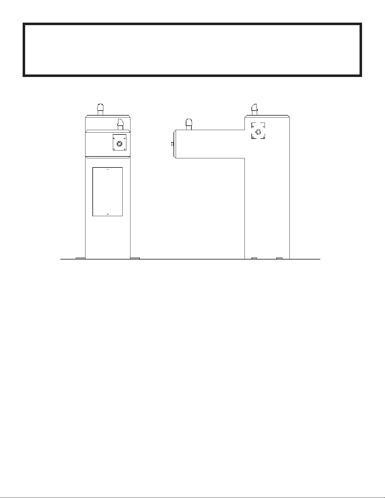
4595 Freeze Resistant Pedest al Barrier Free S tone Fount ain
STOP!
PLEASE READ THE FOLLOWING
INFORMATION.
• INSTALLATION INSTRUCTIONS FOR THE 4595FR FTN.
WITH 97482C DUAL VALVE CONTROL ASSEMBLY ARE
LOCATED ON PAGES 2 - 5.
• INSTALLATION INSTRUCTIONS FOR THE 4595FR FTN.
WITH SANITARYFR2 VALVE ARE LOCATED ON PAGES
6 - 12.
INSTALLER
4595FR Fountains are among the easiest to install Fountains on the market today. To assure
you install these models easily and correctly, PLEASE READ THESE SIMPLE INSTRUCTIONS
BEFORE ST ARTING THE INSTALLA TION. CHECK YOUR INST ALLA TION FOR COMPLIANCE
WITH PLUMBING , ELECTRICAL, AND OTHER APPLICABLE CODES. After installation, leave
these instructions with the Fountain for future reference.
IMPORTANT
THE GROUNDING OF ELECTRICAL EQUIPMENT SUCH AS TELEPHONE, COMPUTERS, ETC. TO WA TER LINES IS A
COMMON PROCEDURE. THIS GROUNDING MA Y BE IN THE BUILDING OR MA Y OCCUR A WA Y FROM THE BUILDING . THIS
GROUNDING CAN CAUSE ELECTRICAL FEEDBACK INTO A FOUNT AIN, CREA TING AN ELECTROL YSIS WHICH CAUSES A
MET ALLIC T ASTE OR AN INCREASE IN THE MET AL CONTENT OF THE WA TER. THIS CONDITION IS A VOIDABLE BY USING
THE PROPER MATERIALS AS INDICA TED. ANY DRAIN FITTINGS PROVIDED BY THE INST ALLER SHOULD BE MADE OF
PLASTIC TO ELECTRICALL Y ISOLA TE THE FOUNT AIN FROM THE BUILDING PLUMBING SYSTEM.
IMPORTANT
ALL SERVICE TO BE PERFORMED BY AN AUTHORIZED SER VICE PERSON
PAGE 1 97461C (Rev. SIB - 6/06)
4595FR-FTN
Owners Manual
4595 Freeze Resistant Barrier Free Stone Pedestal Fountain
with 97482C Dual V alve Control Assembly
IMPORTANT! INSTALLER PLEASE NOTE
Do not pull up on lines coming out of the PVC column. This raises the water valve above the frost line with
disastrous results.
General Installation Tips
1. Be sure to flush water supply line before you connect it to the inlet fitting on Freeze Resistant Valve System.
2. There are two drain lines required for this unit. One for the drinking fountain basin drain and one for the valve/water supply line system. The bowl drain is the 3/4"
PVC fitting at the bottom of the 6" PVC tube and the valve drains through the small holes in the PVC cap. Provide ample drainage for these two items. It's always
better to have too much then not enough.
3. The column (6" PVC tube) must remain vertical. Be sure it remains vertical when backfilling the excavating trench.
4. When the concrete pad, for mounting the fountain, is poured, be sure to allow adequate space around the top of the column so that the flexible cap may be
removed for servicing the valve.
5. We recommend that the top of the column be flush or slightly above the top height of the concrete pad.
6. You should test the unit before you backfill. Simply blow on the clear, small diameter tubing. A steady stream should flow from the braided tubing line. When air
pressure is removed from the clear tubing the water stream should stop.
7. Once you have tested the valve, backfilled the hole and poured the concrete mounting pad you are ready to set the fountain. After bolting the fountain in place
connect the air control valve tubing, supply water tubing and drain lines. The water supply line must have a straight run from the basin bubbler down to the control
valve. If a straight run is not maintained water will become trapped and freeze leaving the unit inoperable. Test the fountain again. If it fails to work, the air
control line may be kinked or connected improperly. Be sure to keep water out of the air control line.
8. These products are designed to operate on 20 psig to 105 psig supply line pressure. If inlet pressure above 105 psig, a pressure regulator must be installed in the
supply line. Any damage caused by reason of connecting this product to supply line pressure lower than 20 psig or higher than 105 psig is not covered by
warranty.
PAGE 297461C (Rev. SIB - 6/06)
4595FR-FTN
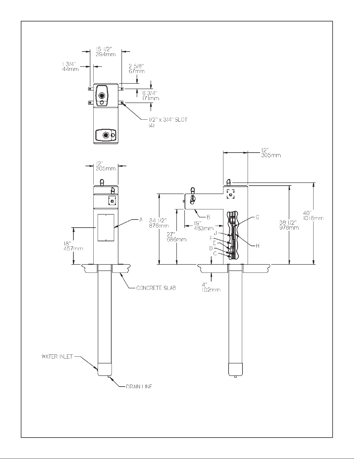
SITE PREPARATION DETAIL FOR THE
4595FR FTN. WHEN USING 97482C DUAL VALVE CONTROL ASSY.
LEGEND
A = ACCESS P ANEL
B = REMOV ABLE BOTTOM COVER
C = 1" PVC DRAIN
D = PRESSURE FITTING 1-1/4" x 3/4"
E = CONNECTOR 1-1/4" TO 1-1/4"
F = 1-1/4" DRAIN TUBE
G = AIR CONTROL LINE
H = 1/4" WATER LINE
J = CONNECTOR FOR AIR CONTROL LINE
FIG . 1
PAGE 3 97461C (Rev. SIB - 6/06)
4595FR-FTN
INSTALLATION INSTRUCTIONS FOR INSTALLING 97482C
DUAL VALVE CONTROL ASSY.
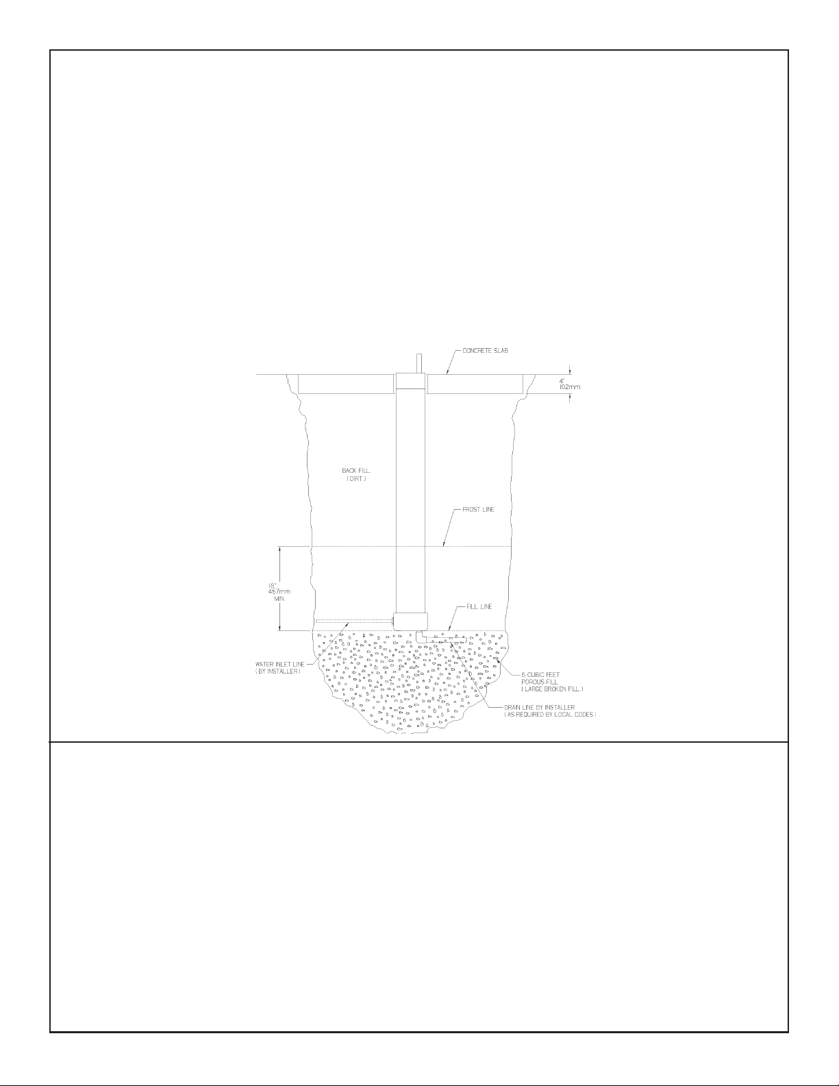
1. Prepare trench for water supply and waste drain lines (if required by local codes). The hole should be deep enough to accommodate the PVC column and 5
cubic feet of porous fill (large broken rock). Additional porous fill may be required due to local ground conditions. (See Site Preparation Detail below).
2. Lay drain lines and water supply lines. Provide service shut off valve for maintenance. Flush the water supply line before attaching to the shut off valve.
3. Set PVC column in excavating pit. Connect the water supply line to the inlet on the PVC column. Remove valve assembly from the PVC column by
carefully pulling up on the connecting tubing. Pressure test the valve assembly for leaks. Check operation of the water valve by blowing on the small
clear diameter tubing. A steady stream of water should flow from the braided tubing. After releasing air pressure from the small clear tubing the water
stream should stop.
4. Replace the water valve into the PVC column. Make sure the supply hose coils into the bottom of the PVC column without any kinks. Cap the PVC
column, protect the ends of the connecting tubes and backfill the trench. Keep the PVC column vertical at all times.
5. Form the concrete mounting pad and locate the fountain anchor bolts in the proper position. (Refer to Rough-in for correct location of anchor bolts.) Pour
concrete and finish. Be sure to keep concrete away from the top of the PVC column to allow removal of PVC cap to allow for future service. Let concrete
set 24 hours minimum before mounting fountain.
6. Double check that the water valve is positioned fully at the bottom of the PVC column. Install insulation into the PVC column and push down onto the top
of the water valve.
7. Mount the fountain onto the anchor bolts. Level and shim fountain as required.
8. Connect the drain line, water line and air control lines. Excess lengths should be trimmed from the tubing. The water supply line must be
positioned for positive drain back out of the fountain and down through the water valve. Any water allowed to be trapped above the frost line will
freeze leaving the unit inoperable. Do not pull up on the connection lines as this could raise the valve above the frost line.
9. Check for proper operation by using fountain push button. If the valve does not work properly check for leaks or kinks in the air control line.
10. After insuring proper operation reassemble fountain. Installation of your fountain is now complete.
SITE PREPARATION DETAIL
FIG . 2
TROUBLE SHOOTING
Insufficient Bubbler Flow: Check that the shut-off valve is wide open. Verify minimum 20 PSI supply pressure. Clean inlet strainer screen located in
the valve body. Clean rubber orifice in flow control located below frost line in bushing between barb fitting and valve.
No Flow: Check for leaks in the air tubing going from the push button to the valve. Make sure the air tubing compression nut is hand tight. Disconnect air
tube from push button. Place finger over air outlet. Push button to test diaphragm. Tighten diaphragm cap screws. Replace diaphragm if necessary.
Continued Insufficient or Varied Height of Bubbler Flow:
• Replace flow control.
• Check for kinks in the tubing.
• Remove the PVC cap from the PVC column. Remove the valve assembly from the PVC column by carefully pulling up on the connecting tubing. Pressure
test the valve assembly for leaks. Check stream height from the bubbler. Stream height is factory set at 35 PSI. If supply pressure varies greatly from this,
adjust the screw on the regulator (Item 20, Page 5, Stream Height Adjustment Detail). Clockwise adjustment will raise stream and counter-clockwise adjustment
will lower stream. For best adjustment stream height should be approx. 1-1/2" (38mm) above the bubbler guard. Replace the valve into the PVC column. Make
sure the supply hose coils into the bottom of the PVC column without any kinks and double check that the valve is positioned fully at the bottom of the PVC
column. Cap the PVC column.
Continuous Bubbler Flow: Insure that push button is not obstructed and springs back to normal position. Remove four screws which secure plastic
diaphragm block to valve body. Pull plastic and rubber diaphragm assembly out of valve body. Locate tiny hole in rubber diaphragm just under lip of plastic
part. Clean debris from this hole. Inspect valve seat for grooves. If valve seat was OK and diaphragm hole was free from debris, inspect rubber button
located at center of floating steel disc in valve diaphragm block assembly. If button is worn, turn disc over or replace it. If diaphragm and seats are in good
condition, stretch spring slightly. Spring is located behind floating stainless steel plate. Insure that air bleed port on valve plastic block assembly is not
plugged.
PAGE 497461C (Rev. SIB - 6/06)

The following items are included with
the 4595FR Fountain
PAR TS LIST
ITEM NO. PART NO.
1
100147140560
2
100322740560
3
101449542550
4
101570540560
5
6
7
8
9
10-A
10-B
11
12
13
14
15
16
17
18
19
20
21
22
23
24
25
26
27
28
*29
30
31
32
NS
NS
NS
15013C
110544942550
110868642550
160270508640
170705042830
400942308640
98287C
40250C
45403C
45476C
50986C
55913C
55960C
56082C
56121C
600985451640
61313C
66346C
66461C
66719C
70683C
75565C
75588C
75589C
97482C
45971C
45788C
45793C
45790C
56092C
56123C
75539C
Drain Gasket
Gasket
Clamp - Hose
Drain Gasket
Bubbler Tube Assy.
Set Screw #8-32 x .125
Socket Head Screw #10-24 x .75
Strainer Plate
Basin
Bubbler
Bubbler Assembly
Tailpipe 1-1/4" x 5-3/8"
Push Button Actuator
Drain Tube
Regulator Holder
Drain Adapter
Pressure Fitting 1-1/4" To 3/4"
Regulator Nut
Drain Elbow 1-1/4"
Drain Plug Assy.
Regulator
Drain Tube
Fitting 1-1/4" x 1-1/4"
Tube Assy.
Union 1/4
Fitting - Double Male Connector
Slip Joint Nut 1-1/4"
Gasket
Dual Control Valve System Complete
Dual Control Valve Assy.
Rainbird Check Valve
Dual Acorn Valve Assy.
Flow Control Fitting
Poly Tubing - 1/4" (Cut To Length) -To Bubbler
Poly Tubing - 1/8" (Cut To Length) -To Actuator
Allen Wrench
DESCRIPTION
4595FR-FTN
BUBBLER DET AIL
10-A, 6
10-B
6, 18
12
27
8
7
19
9
4
5
24
26
2
2
1
21
13
22
25
25
2
2
5
24
7
8
19
9
4
1
15
27
26
11
* Includes items 30, 31, 32
30
32
31
Dual Valve Assy.
(Item 29)
23
14, 20
17
Stream Height
Adjustment
3
Stream Height
Adjustment
Detail
21
22
16
28
PRINTED IN U.S.A.
FOR PARTS, CONTACT YOUR LOCAL DISTRIBUTOR OR CALL 1.800.323.0620
PAGE 5 97461C (Rev. SIB - 6/06)

4595FR-FTN
Owners Manual
4595 Freeze Resistant Barrier Free Stone Pedestal Fountain
with SanitaryFR2 V alve
IMPORTANT! INSTALLER PLEASE NOTE
Tubing must be cut to the right length. Do not coil any excess tubing or it will cause valve to malfunction.
General Installation Tips
1. Prepare trench for water supply and waste drain lines. The hole should be deep enough to accommodate the PVC column.
Additional porous fill and drain pipe may be required due to local ground conditions. Cut the PVC column to fit desired bury
depth. Set PVC column in excavating pit.
2. Lay drain lines and water supply lines. Provide service shut off valve for maintenance. Flush the water supply line before
attaching to the shut off valve.
Other Notes:
• The details on the attached pages show a suggested installation method. Depending on the climate and environmental
conditions the suggested installation may be modified.
• Overall - for the freeze resistant to function properly the valve must be installed in a non-freezing area.
PAGE 697461C (Rev. SIB - 6/06)

4595FR-FTN
SUGGESTED SITE PREPARATION DETAIL FOR THE
4595FR FTN. WHEN USING THE SANITARYFR2 VALVE
FIG . 1
PAGE 7 97461C (Rev. SIB - 6/06)

4595FR-FTN
SUGGESTED SITE PREPARATION DETAIL FOR THE
4595FR FTN. WHEN USING THE SANITARYFR2 VALVE
AIR GAP ASSY.
SUPPLIED WITH VAL VE
1-1/2 DRAIN TUBE
SUPPLIED WITH FTN.
FIG . 2
1-1/2 DRAIN TUBE
SUPPLIED BY INST ALLER
Detail A
LEGEND
A = ACCESS P ANEL
B = REMOV ABLE BOTTOM COVER
PAGE 897461C (Rev. SIB - 6/06)

FOUNT AIN CONNECTIONS
4595FR-FTN
PLUMBING CONDUIT
(BY INST ALLER)
TO VAL VE
FIG . 3
INSTRUCTIONS FOR CONNECTING TUBES FROM VALVE TO FOUNTAIN(S)
Step 1 - Insert the 1/8” O.D. tube(s) (Labeled A & B) into the connector(s) (provided with fountain). Insert the 1/8”
O.D. tube(s) coming from the fountain(s) push button actuator(s) into the connector(s). Trim any excess
length.
Step 2 - Secure the 1/8” O.D. tube(s) (Labeled C & D) to the waste line assembly. This line is a vent line and
should be open to the air.
Step 3 - Insert the 1/4” O.D. tube(s) (Labeled E & F) into the 1/4” union(s) (provided with valve assembly). Insert the
1/4” O.D. water lines coming from the fountain(s) into union(s). Trim any excess length.
Step 4 - Insert the 1/4” O.D. tube (Labeled G) into the air gap assembly.
Step 5 - Secure the 1/4” O.D. tube (Labeled H) to the waste line assembly. This line is a vent line and should be
open to the air.
LABEL E (WATER LINE)
LABEL B
(ON/OFF CONTROL LINE
FOR BUBBLER TWO)
LABEL C (VENT LINE)
LABEL H (VENT LINE)
LABEL D (VENT LINE)
LABEL G (DRAIN LINE)
LABEL F (WATER LINE)
LABEL A
(ON/OFF CONTROL LINE
FOR BUBBLER ONE)
FOUNT AIN CONNECTIONS
FOUNT AIN CONNECTIONS
PAGE 9 97461C (Rev. SIB - 6/06)

4595FR-FTN
Stream Height
6
Adjustment
5, 13
7
7
7
16
FIG . 4
17
12
3
2
14
4
FIG . 5
SEE DET AIL B
7
15
FIG . 6
PAGE 1097461C (Rev. SIB - 6/06)
8
8
8
8
15
17
DET AIL B

The Following Items are included with
the SanitaryFR2 Valve
P ARTS LIST
ITEM NO.
1
2
3
4
5
6
7
8
9
10
11
12
13
14
15
16
17
18
19
NS
PAR T NO.
110175443890
28424C
40045C
45807C
50986C
56082C
56092C
56123C
56185C
56187C
56203C
56235C
61313C
70817C
70828C
75639C
75642C
75652C
75653C
70683C
Hex Nut - 3/8-16
Bracket - Regulator Holder
Hex Nut - 1-5/16
Dual Valve
Regulator Holder
Regulator Nut
Poly Tubing - 1/4” (Cut To Length)
Poly Tubing - 1/8” (Cut To Length)
Canister
Trap - Adaptor 1-1/2
Air Gap Assy.
Fitting - 1/2” Union w/Strainer
Regulator
Fitting - Elbow 1/4 Stem x 1/4 Tube
Fitting - Connector 1/4 x 1/4 NPTF
Fitting - Elbow 1/4 x 1/4 NPTF
Fitting - Adaptor 1/4 NPT x 1/2 NPT
U-Bolt
Nylon Strap - 6 ft.
Fitting - Union 1/4
DESCRIPTION
4595FR-FTN
19
18
1
10
9
11
FIG . 7
FIG . 8
FIG . 9
PAGE 11 97461C (Rev. SIB - 6/06)

4595FR-FTN
The Following Items are included with
the 4595FR Fountain
PAR TS LIST
ITEM NO. PART NO.
100147140560
20
100322740560
21
101570540560
22
23
24
25
26
27
28-A
28-B
29
30
31
32
33
34
35
36
37
38
NS
NS
NS
NS
15013C
110544942550
110868642550
160270508640
170705042830
400942308640
98287C
40250C
45403C
45476C
55913C
56121C
600985451640
66346C
70683C
75588C
75589C
75565C
56092C
56123C
75539C
Drain Gasket
Gasket
Drain Gasket
Bubbler Tube Assy.
Set Screw #8-32 x .125
Socket Head Screw #10-24 x .75
Strainer Plate
Basin
Bubbler
Bubbler Assembly
Tailpipe 1-1/4" x 5-3/8"
Push Button Actuator
Drain Tube
Drain Adapter
Drain Elbow 1-1/4"
Drain Plug Assy.
Drain Tube
Union 1/4
Slip Joint Nut 1-1/4"
Gasket
Fitting - Double Male Connector
Poly Tubing - 1/4"
Poly Tubing - 1/8" (Cut To Length) -To Actuator
Allen Wrench
DESCRIPTION
(Cut To Length) -To Bubbler
Trouble Shooting
Insufficient Bubbler Flow: Check that the shut-off valve is wide open.
Verify minimum 20 PSI supply pressure. Clean inlet strainer screen located in
the valve body. Clean rubber orifice in flow control located below frost line in
bushing between barb fitting and valve.
No Flow: Check for leaks in the air tubing going from the push button to the
valve. Make sure the air tubing compression nut is hand tight. Disconnect air
tube from push button. Place finger over air outlet. Push button to test
diaphragm. Tighten diaphragm cap screws. Replace diaphragm if necessary.
Continued Insufficient or Varied Height of Bubbler Flow:
• Replace flow control.
• Check for kinks in the tubing.
• Remove the cleanout plug from the PVC column. Remove the valve
assembly from the PVC column by carefully pulling up on the strap and
connecting tubing at the same time. Pressure test the valve assembly for
leaks. Check stream height from the bubbler. Stream height is factory set at
35 PSI. If supply pressure varies greatly from this, adjust the screw on the
regulator (Item 13, Page 10, Fig. 4). Clockwise adjustment will raise stream
and counter-clockwise adjustment will lower stream. For best adjustment
stream height should be approx. 1-1/2" (38mm) above the bubbler guard.
Replace the valve into the PVC column. Make sure the supply hose coils into
the bottom of the PVC column without any kinks and double check that the
valve is positioned fully at the bottom of the PVC column. Cap the PVC
column.
Continuous Bubbler Flow: Insure that push button is not obstructed
and springs back to normal position. Remove four screws which secure plastic
diaphragm block to valve body. Pull plastic and rubber diaphragm assembly
out of valve body. Locate tiny hole in rubber diaphragm just under lip of
plastic part. Clean debris from this hole. Inspect valve seat for grooves. If
valve seat was OK and diaphragm hole was free from debris, inspect rubber
button located at center of floating steel disc in valve diaphragm block
assembly. If button is worn, turn disc over or replace it. If diaphragm and
seats are in good condition, stretch spring slightly. Spring is located behind
floating stainless steel plate. Insure that air bleed port on valve plastic block
assembly is not plugged.
30
33 3738
28-A, 24
28-B
BUBBLER DET AIL
29
25
26
34
27
22
21
23
36
35
20
30
21
23
36
25
26
34
27
22
20
32
38
37
29
31
FOR PARTS, CONTACT YOUR LOCAL DISTRIBUTOR OR CALL 1.800.323.0620
PAGE 1297461C (Rev. SIB - 6/06)
Included with
SanitaryFR2
V alve
PRINTED IN U.S.A.
 Loading...