

Page 1
4420BFDB_FTN_A LK4420BFDB_FTN_A
Owners Manual
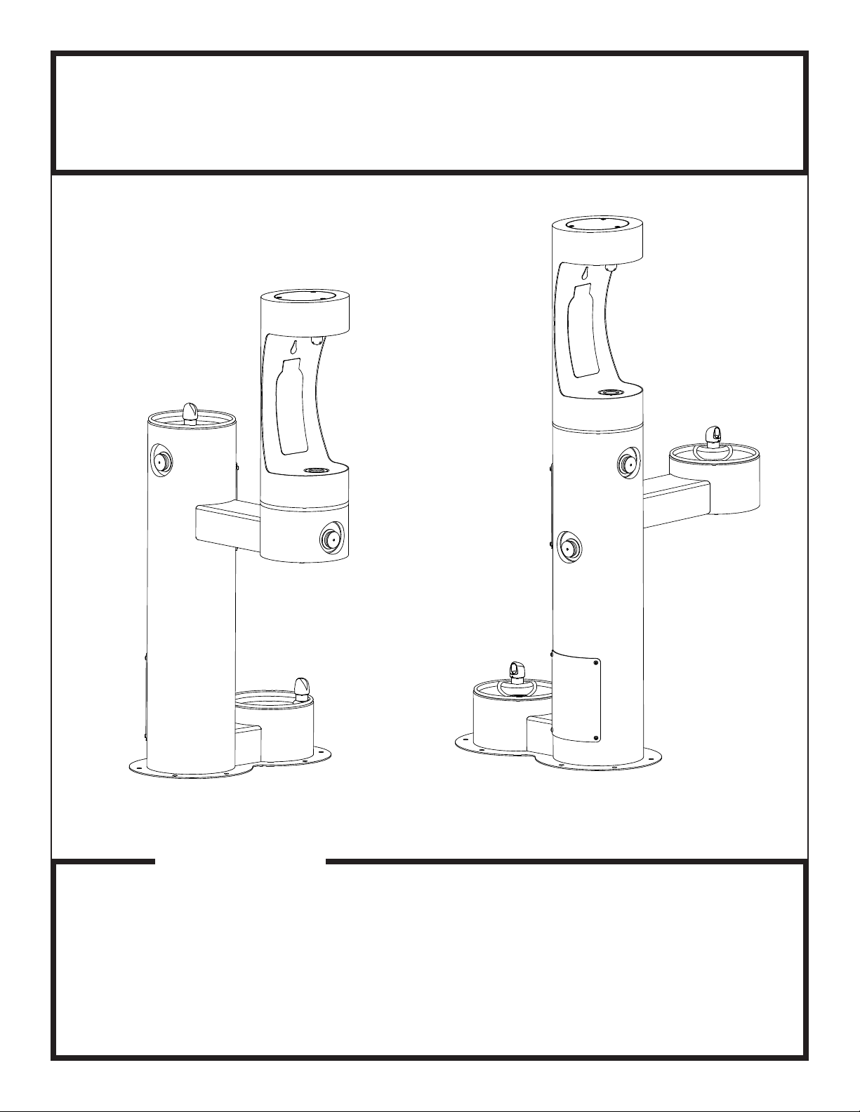
Models 4420BF1LDB* and 4420BF1UDB*
Bi-Level Tubular Bottle Filler Fountain with Pet fountain
Models (LK)4420BF1LDB* Models (LK)4420BF1UDB*
INSTALLER
4420BFDB Fountains are among the easiest to install Fountains on the market today.
To assure you install these models easily and correctly, PLEASE READ THESE
SIMPLE INSTRUCTIONS BEFORE STARTING THE INSTALLATION. CHECK YOUR
INSTALLATION FOR COMPLIANCE WITH PLUMBING, ELECTRICAL, AND OTHER
APPLICABLE CODES. After installation, leave these instructions with the Fountain for
future reference.
PAGE 1
1000003948 (Rev. B - 03/20)
Page 2

4420BFDB_FTN_A LK4420BFDB_FTN_A
INSTALLATION INSTRUCTIONS
IMPORTANT
ALL SERVICE TO BE PERFORMED BY AN AUTHORIZED SERVICE PERSON
IMPORTANT! INSTALLER PLEASE NOTE.
THE GROUNDING OF ELECTRICAL EQUIPMENT SUCH AS TELEPHONE, COMPUTERS, ETC. TO WATER LINES
IS A COMMON PROCEDURE. THIS GROUNDING MAY BE IN THE BUILDING OR MAY OCCUR AWAY FROM THE
BUILDING. THIS GROUNDING CAN CAUSE ELECTRICAL FEEDBACK INTO A FOUNTAIN, CREATING AN
ELECTROLYSIS WHICH CAUSES A METALLIC TASTE OR AN INCREASE IN THE METAL CONTENT OF THE
WATER. THIS CONDITION IS AVOIDABLE BY USING THE PROPER MATERIALS AS INDICATED. ANY DRAIN
FITTINGS PROVIDED BY THE INSTALLER SHOULD BE MADE OF PLASTIC TO ELECTRICALLY ISOLATE THE
FOUNTAIN FROM THE BUILDING PLUMBING SYSTEM.
1. This fountain is to be mounted on a smooth, at, nished surface with adequate support structure. NOTE: Mounting structure
must be capable of supporting 300 lb. load on fountain.
2. Refer to rough-in for plumbing.
3. Install shut-o valve on water supply. (Valve not furnished)
4. Locate and install fountain using 3/8" minimum fasteners. (Fasteners not furnished)
5. Prior to installing the bottle ller to the center mounting position of fountain, insert the drain pipe (Item #15) by positioning the
short end of drain pipe through mounting plate of bottle ller. Next, place the aesthetic collar (item # 29) onto the center
mounting position of the fountain ensuring the vertical edge of the collar is upright and the curved edge sits below the mount
ing surface. Mount bottle ller to fountain with collar centered between the two pieces. Install bottle ller to fountain and secure
with supplied hardware.
6. Prior to installing the bottle ller to the arm mount of fountain, insert the drain pipe (Item #14) into the arm tunnel and adjust
drain to lean to the left side of the arm when facing the button. Next, place the aesthetic collar (Item # 29) onto the arm
mounting position of the fountain ensuring the vertical edge of the collar is upright and the curved edge sits below the
mounting surface. Mount bottle ller to arm with collar centered between the two pieces. Install bottle ller to arm being
sure drain tube is above mounting plate of ller. Install ller to fountain and secure with supplied hardware.
7. Connect water supply and fountain drain. Connect drain waste "Tee" to fountain drain tubes. Connect outlet of "Tee" to
drainage system. Water connection and drain must comply with local codes.
8. Turn on water supply and check all connections for leaks.
CAUTION: This fountain is rated for inlet water pressure of 20-105 PSI. A pressure reducing regulator should be used if the
inlet water supply exceeds 105 PSI. Any damage caused by reason of connecting this product to supply line
pressures lower than 20 PSI or higher than 105 PSI is not covered by warranty.
9. Water supply 3/8" O.D. unplated copper tube. Waste 1-1/2" IPS. Contractor to supply waste trap and service stop valve in
accordance with local code.
10. Connecting lines to be made of unplated copper and should be thoroughly ushed to remove all foreign matter before being
connected to fountain. This fountain is manufactured in such a manner that it does not in any way cause taste, odor,color,
or sediment problems.
11. Connect fountain to supply line with a shut-o valve and install a 3/8" unplated copper water line between the valve and
the fountain. Remove any burrs from outside of water line. Push the tubes straight into the ttings until they reach a
positive stop, approximately 3/4" (See Fig. 3). DO NOT SOLDER TUBES INSERTED INTO PLASTIC FITTINGS AS
DAMAGE TO THE O-RINGS MAY RESULT.
1000003948 (Rev. B - 03/20)
PAGE 2
Page 3

26"
4420BFDB_FTN_A LK4420BFDB_FTN_A
10"
254mm
O
* ADA REQUIREMENT
57 3/16"
1453mm
37 3/16"
14 9/16"
660mm
22"
559mm
3"
76mm
371mm
945mm
27 1/8"
689mm
*
C
4420BF1LDB
19"
483mm
29"
A
1-1/2" DRAIN
737mm
10"
254mm
FINISHED FLOOR
O
40 5/16"
1025mm
RIM
HEIGHT
12.00" B.C.
O
.500" HOLES
O
8 -
TWO
EQUALLY SPACED ON
14"
(2 PL)
356mm
O
10"
254mm
41 7/16"
HEIGHT
1053mm
ORIFACE
8"
203mm
O
B
B
PAGE 3
30"
6 9/16"
167mm
762mm
1000003948 (Rev. B - 03/20)
LEGEND
A = 3/8" O.D. UNPLATED COPPER TUBE CONNECT - SHUT OFF VALVE BY OTHERS
B = ACCESS PANEL ( 8" X 10" )
C = REMOVABLE BOTTOM COVER
Page 4

4420BF1UDB
4420BFDB_FTN_A LK4420BFDB_FTN_A
4420BF1UDB
10"
254mm
O
* ADA REQUIREMENT
3"
76mm
22"
559mm
10"
12.00" B.C.
O
.500" HOLES
O
EQUALLY SPACED ON
TWO
8 -
14"
356mm
(2 PL)
O
254mm
O
34 9/16"
878mm
HEIGHT
ORIFACE
RIM
33 7/16"
850mm
HEIGHT
27 1/8"
689mm
*
A
1-1/2" DRAIN
FINISHED FLOOR
19"
C
483mm
26"
29"
737mm
660mm
10"
254mm
O
14 9/16"
371mm
64 1/16"
1627mm
B
44 1/16"
1119mm
8"
203mm
B
6 9/16"
167mm
30"
762mm
1000003948 (Rev. B - 03/20)
PAGE 4
LEGEND
A = 3/8" O.D. UNPLATED COPPER TUBE CONNECT - SHUT OFF VALVE BY OTHERS
B = ACCESS PANEL ( 8" X 10" )
C = REMOVABLE BOTTOM COVER
Page 5
21
27
38
62
11
24
22
27
13
10
42
62
49
30
61
63
20
29
6 SEE NOTE 13
78SEE NOTE 11
20
28
3748
21
10
13
1659
52 OR
33
25
43
43
61
16
3SEE NOTE 5
34
33 45
63
29
22
24
24
11
11
37
3748
48
52 OR
22
20
29
28
63
61
45
8SEE NOTE 13
61
62
61
62
61
62
61
59
28
4420BFDB_FTN_A LK4420BFDB_FTN_A
18, 27
2
28
27
28
22
27
ARM ONLY 14
21
15
25
11
29
23
13
16
PAGE 5
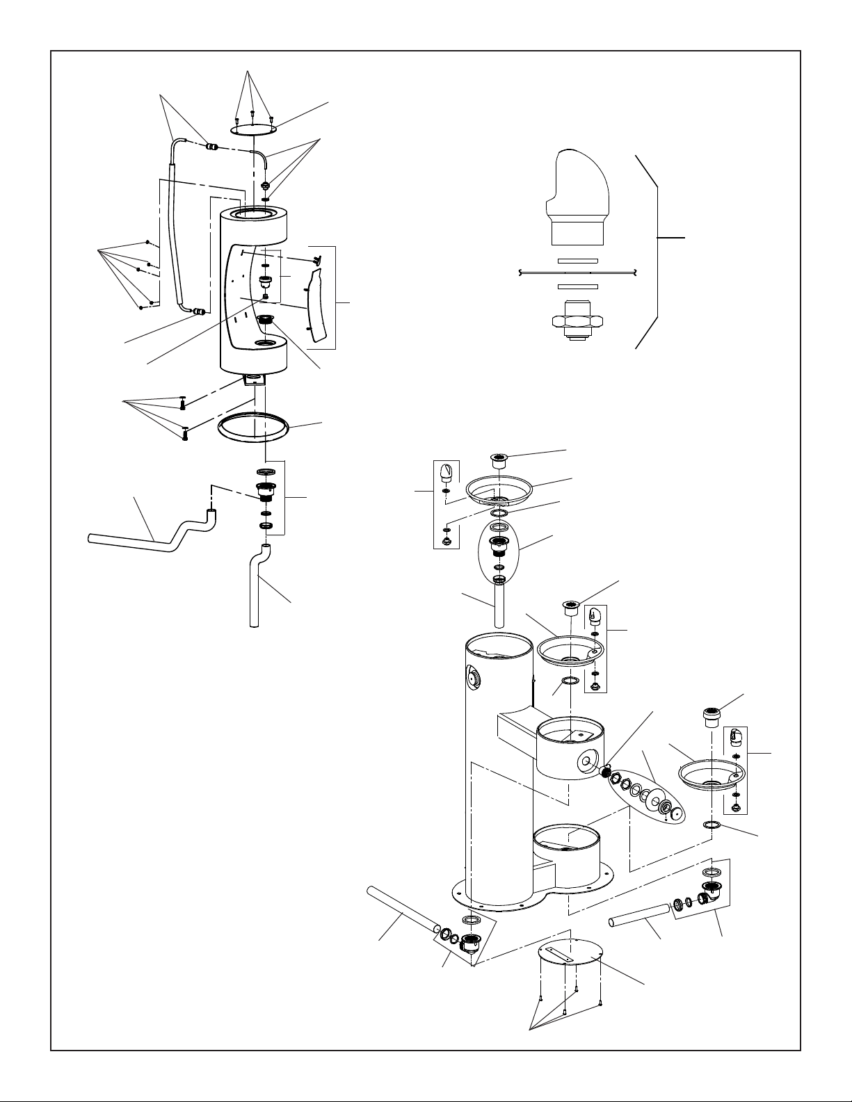
26
3
BASIN
Vandal-Resistant Bubbler
FIG. 1
4
1
4
25
19, 27
1
4
16
4
16
20
24
1
8
26
10
9
17
6
1000003948 (Rev. B - 03/20)
Page 6

4420BFDB_FTN_A LK4420BFDB_FTN_A
RE
O
TROUBLESHOOTING AND MAINTENANCE
ACTUATION OF QUICK CONNECT WATER FITTINGS:
Fountain is provided with lead-free connectors which utilize an
o-ring water seal. To remove tubing from the tting, relieve water
pressure, push in on the gray collar while pulling on the tubing. (see
Fig.2) To insert tubing, push tube straight into tting until it reaches
a positive stop, approximately 3/4".
1/4" O.D. TUBE
WATER INLET
TO COOLER
FIG. 2
OPERATION OF QUICK CONNECT FITTINGS
OPERATION OF QUICK CONNECT FITTINGS
SIMPLY PUSH IN
SIMPLY PUSH IN
TUBE TO ATTACH
TUBE TO ATTACH
A B C
3/8" O.D. UNPLATED COPPER TUBE CONNECT
COLD WATER SUPPLY
NOTE: WATER FLOW
DIRECTION
TUBE IS SECURED
TUBE IS SECURED
IN POSITION
B CA
IN POSITION
BUILDING WATER INLET
SERVICE STOP
(NOT FURNISHED)
PUSH IN COLLET
PUSH IN COLLET
TO RELEASE TUBE
TO RELEASE TUBE
PUSHING TUBE IN BEFORE
PUSHING TUBE IN BEFO
PULLING IT OUT HELPS TO
PULLING IT OUT HELPS T
RELEASE TUBE
FIG. 3
ITEMIZED PARTS LIST
ITEM
NO.
1
2
3
4
5
6
7
8
9
10
11
12
13
14
15
16
17
18
19
20
21
22
23
24
25
26
27
28
29
NS
NS = Not Shown
*select color option to complete part number
PART NO.
28467C
1000003814*
40551C
0000000325
1000003812*
1000003813*
45926C
45724C
45726C
0000000466
45931C
55996C
66346C
66816C
66815C
97446C
101570540560
75724C
97247C
98678C
98530C
98679C
98680C
98681C
1000003692
1000003693
98682C
1000003694
1000003695
98683C
98684C
98685C
98686C
1000005456
1000003490
Basin
Cover - Round Plate
Tailpipe
Kit - Drain Plug/Gasket
Access Panel
Bottom Cover
Drain Tube - 1-1/2" x 27-1/2" Lg.
Tailpipe - 1-1/4" x 10"Lg.
Drain Plug 1-1/2" (Dog Bowl)
Kit - Bubbler (Dog Bowl)
Plug - Drain (BF)
In - Line Strainer
Drain Tube
Tube - Drain (Arm Only)
Tube - Drain
Kit - Bubbler (VR)
Gasket
Screw - 1/4"x20 x 3/4" LG. Pinned Torx
Kit - VR Torx Screws/Bit
Kit - 1.0 GPM Regulator (BF Only)
Kit Kit - Nozzle
Kit - Aerator/Key
Kit - Blank Bottle Filler Trim
Kit - LK4420BFDB Bottle Filler Trim
Kit - 4420BFDB Bottle Filler Trim
Kit - Push Button w/Blank Nameplate
Kit - Push Button w/LK4420BFDB Nameplate
Kit - Push Button w/4420BFDB Nameplate
Kit - Plastic Drain
Kit - 90° Plastic Drain
Kit - 4400 Series Hardware
Kit - Bottle Filler Waterway
Aesthetic Collar
Drain Tube (Not Shown)
DESCRIPTION
FIG. 4
STREAM HEIGHT ADJUSTMENT:
Stream height is factory set at 35 PSI. If supply pressure
varies greatly from this, insert a small straight bladed
screwdriver through the access hole in the center of the
push button and turn the adjustment screw. Clockwise
adjustment will raise the stream and counterclockwise
adjustment will lower the stream. For best adjustment,
the stream should be approximately 1 1/2" above the
top of the bubbler . (See Fig. 4)
See Fig. 4
12
5
27
10
11
5
*FINISH COLOR OPTIONS – Choose color option to
complete your model number, add as sux example:
4420BF1UDBEVG
Matte nish: Evergreen = EVG
Gloss nish:
Beige = BGE Gray = GRY Terracotta = TER
Black = BLK Orange = ORN White = WHT
Blue = BLU Purple = PUR Yellow = Y LW
Brown = BRN Red = RED
7
PRINTED IN U.S.A.
Halsey Taylor – halseytaylor.com
Elkay – elkay.com
1000003948 (Rev. B - 03/20)
FOR PARTS CONTACT YOUR LOCAL DISTRIBUTOR OR CALL TECHNICAL SERVICES AT 1.800.834.4816
1333, BUTTERFIELD ROAD, DOWNERS GROVE, ILLINOIS 60515
PAGE 6
 Loading...