

Page 1

Two Way Amp for Listen-in ELK-M1TWA
APPLICATION:
The ELK-M1TWA is an accessory for the ELK-M1 and ELK-
M1EZ8 controls. It provides 3 zones of amplified speaker
outputs with adjustable volume, along with 3 zones of
microphone inputs. The M1TWA can be used to add two
way listen-in to the M1 Control or to just add amplified
speakers at keypads and other locations in a building. Each
of the 3 amplified speaker zones can drive a maximum
combined impedance range of ~4 to 32 Ohms, permitting
multiple speakers to be connected. Each zone includes a
mute option that is triggered via an output from the control.
The 3 microphone zones can handle up to 4 individual
microphones each. Two way listen-in operation is
programmed and operated from the control and includes the
ability to select individual mic zones for listening or to select
"all" microphone zones. While multiple M1TWA units may
be daisy chained together to increase the total number of
amplified speakers and microphones, the max. number of
zones will always be 3.
FEATURES:
• 3 Amplified Speaker Zones
• Adjustable Speaker Volume Control by Zone
• Selectable Mute by Zone
• 3 Microphone Input Zones (up to 4 mics per zone)
• Selectable Mic Listen by Zone or Select ALL
• Interfaces to ELK-M1 or ELK-M1EZ8 Controls
SPECIFICATIONS:
• Output Impedance Range: ~4 to 32 Ohms per SPKR Output
Multiple speakers on any single output must be parallel or
serial connected to maintain rated impedance
• Amplifier Rating: 1/2 Watt per Speaker Output
• Microphone Inputs: Up to 4 Mics per input. Compatible with:
ELK-M1TWM, ELK-M1TWS
• Operating Voltage: 9 to 14 Volts D.C.
• Current Draw: 15mA nominal, 1000mA (1 Amp) maximum
• Microphone Current Draw. 5mA each
• Housing Dimensions: 4.25" x 6.375" x 2.125"
• Circuit Board Dimensions: 2.25" x 3.95"
NOTE: Use of Two Way Listen-in may be regulated by local or
state law and/or ordinance. It is the responsibility of the Installer to check before using this feature.
PO Box 100 • Hildebran, NC 28637 USA • 828-397-4200 Voice • 828-397-4415 Fax
http://www.elkproducts.com • email: info@elkproducts.com
L619 01/25/08
Page 2
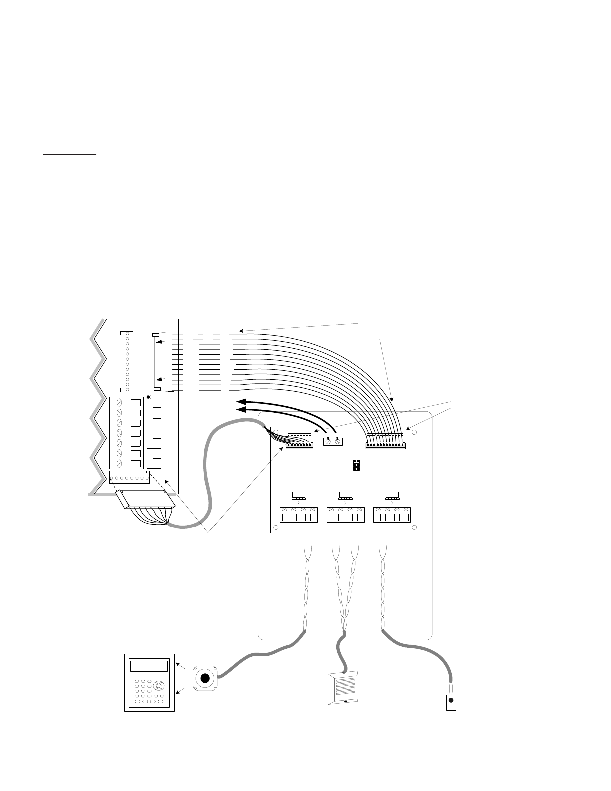
ELKM1TWA INSTALLATION
Equipment included with ELK-M1TWA: M1TWA Interface board, 8 Conductor J7 cable, and 12 Conductor J16 Cable
Additional equipment needed but not supplied: Speaker(s), Speaker/Microphone combo(s), or Microphone(s) only.
1. Mount the M1TWA as close to the M1 Control board as possible. The board may be removed from plastic base for alternate mounting methods.
2. Remove power from the control and all components before making any electrical connections.
3. Install your choice of Speakers [eg: ElkSP12F, ElkSP35, etc.] or Microphone only, or Speaker with built-in Microphone [ELK-M1WS]. Recom-
mended wiring is 22 to 24 gauge UTP (unshielded twisted pair) for the microphones, and 18 to 20 gauge for the speakers.
4. Connect the speaker(s) and or microphone(s) as per diagram below. The M1TWA has 3 separate zones for microphones and speakers. Each
zone has its own amplifier and volume adjustment. The control activates specific voltage outputs thru the 12 conductor cable in order to control
the M1TWA. When two-way listen-in is active the control turns on outputs 7, 8, or 9 (or all three) to select mic zones 1, 2, 3 respectively.
Output 10 is also turned on while listen-in is active to collectively mute all spkr zones.
Special Option: Three jumpers on the board labeled "Override" allow you to selectively mute any of the 3 spkr zones utilizing the M1 Rules.
Simply place a shorting jumper on any of these option jumpers 11, 12, 13 and then write a rule to turn on output 11, 12, or 13 to selectively mute
spkrs 1, 2, or 3 respectively. This can be especially handy to turn off specific speakers during special hours or conditions.
5. Connect the 8 conductor cable from connector J7 on the Control to connector J2 on the M1TWA. This feeds the line level audio and mic inputs.
6. Connect the 12 conductor cable from connector J16 on the Control to connector J4 on the M1TWA. The RED and Black wires (+12V & Neg)
wires are the primary power for the M1TWA. NOTE: It may be required to connect a separate "supplimental" power source to the two (2)
power input screw terminals on the M1TWA, depending on the number of speakers connected and the existing load on the control panel.
7. Use the ElkRP Programming software or local Keypad programming to navigate to "Menu 07 - Global System Definitions and set Option 31 to
YES. This enables the listen-in feature and informs the Control that an M1TWA board is present.
PLEASE NOTE: When an ELKM1TWA is connected to the Control Outputs 7, 8, 9, and 10 automatically become assigned for
triggering and muting the Microphone and speaker zones as necessary during operation. Basically, when an ELKM1TWA is
connected these 4 Outputs CANNOT BE USED for any other purpose.
8. The Control and M1TWA can now be powered up and tested.
M1 Control (Right Side Terminals)
+12V
J16
NEG
16
15
14
13
12
11
10
9
8
7
N/CCOMN/O
OUT3OUT2
J16 Outputs 7 - 16
+12V switched positive rated at 40mA. ea.
+VAUX
NEG
OUT 16
OUT 15
OUT 14
OUT 13
OUT 12
OUT 11
OUT 10
OUT 9
OUT 8
OUT 7
Red
+12V
Black
NEG
White
Green
Brown
Blue
Orange
Yellow
Violet
Gray
Pink
Tan
To 12 VDC
"Aux" Power
Source
+
-
+
-
OUT1
J7
AUDIO NETWORK INTERFACE
Connect 8 conductor cable (supplied with M1TWA) from:
"J7" on Control to "J2" on M1TWA.
This diagram depicts three different connection examples.
Many other combinations are possible.
Under the following circumstances each Spkr Output
can be used to power multiple speakers.
A) The combined speaker loading CANNOT be lower than 4 Ohms
B) At some point an additional (separate) power source may be
needed for the M1TWA depending on the number of speakers
connected and the existing load on the control panel.
Keypad 2
ElkSP12F or equiv alent
8 to 32 Ohm Speaker
Spkr 1 terminals connected to ElkSP12F speaker(s) located behind or adjacent
* Because the SP12F has a 32 Ohm impedance up to 7 may be wired in parallel.
Example 1:
to Keypad.
Hookup Diagram for ELK-TWA Audio Amp & Listen-in I nterface
J7 'OUT' to EXPAND
J7 'IN' from CNTRL
ELK-M1TWA
Amp 1 Volume
MIC 1 SPKR1
Connect 12 wire 'double ended' cable (supplied with
M1TWA) from: "J16" on Control to "J4" on M1TWA.
1
NEG +12V
J1
1
J2
OverRide
11
12
13
Amp 2 Volume
Min Max Min MaxMin Max
MIC 2 SPKR2 MIC 3 SPKR3
ElkM1TWS or
equivalent Spe aker
Example 2:
Spkr 2 terminals connected
to a ElkM1TWS Speaker/
Mic for two-way listen-in
application.
J16 'OUT to EXPAND
J16 'IN' from CNTR L
Amp 3 Volume
(8 Ohm)
1
J3
1
J4
R3R2R1
Zone 3 used to connect an
M1TWM (microphone only) for
two-way listen-in application.
Connectors J1 and J3 can be used
if it becomes necessary to daisy
chain to additional peripherals.
IMPORTANT NOTE:
Use of Two Way Listen-in may
be regulated by local or state
law and/or ordinance. It is the
responsibility of the Installer to
check before using this feature.
ElkM1TWM or
equivalent
Microphone
Example 3:
Page 3

OPERA TION
Depending on the Control panel being used a two way listen-in session can be initiated as follows:
A. The M1 or M1EZ8 Control can initiate a two way listen-in following an alarm from a zone that has the "two way listen-in" option
enabled. After the alarm has transmitted, the controls dialer will hold the line for up to 60 seconds, allowing the CS Operator to press
the DTMF "Dual tone multi frequency" command *55* to initiate listen-in. If this tone command is not received, the dialer will hang-up
and release the phone line.
B. The M1's telephone remote control feature will allow an offsite initiated two way listen-in session to be initiated. (THIS FEATURE IS
NOT AVAILABLE WITH THE M1EZ8 CONTROL) First, call the M1 control and wait for it to answer. As soon as the phone is answered
you will need to press the "*" key at least three times in quick succession. The control should then emit several beeps of its own.
This is a prompt for you to enter a valid passcode to access the remote control feature. Once you hear the remote menu and welcome
you can then press "7" to select option 7 “Audio Monitor”. Follow the Tone Commands below to navigate through the system.
IMPORTANT:
T elephone remote on the M1 must be enabled from the Installer Programming, Menu 07 - "Global System Definitions,
Opt G01". In addition, from this same menu you must also enable the "Rings Until Auto Answer , Opt 29" by programming it to the desired number of rings in which you want the phone to be answered.
NOTE: An active two way session terminates automatically after 3 minutes, unless manually extended using tone command 7.
DTMF TONE COMMAND
DTMF *55* BEGIN LISTEN-IN - For use by the Central Station to initiate listen-in.
DTMF 1 TALK - Mutes (turns off) all microphone inputs and turns on the TWA speaker amplifiers as well as Output 1 on the main
control. It should now be possible to make announcements to the premise.
DTMF 2 LISTEN - Mutes (turns off) all TWA speaker amplifiers as well as Output 1 on the main control. It should now be possible
to listen to any premise activity occurring within range of the microphones.
DTMF 3 MAX. SENSITIVITY - Raises the gain on microphone sensitivity.
DTMF 4 MICROPHONE SELECT -
40 Re-selects ALL microphones
41 Selects only Microphones connected to Mic 1 (Zn 1) terminals
42 Selects only Microphones connected to Mic 2 (Zn 2) terminals
43 Selects only Microphones connected to Mic 3 (Zn 3) terminals
NOTE: Initially ALL 3 mic zones should be active when Listen (DTMF 2) is pressed.
DTMF 5 - [future use]
DTMF6 LOW SENSITIVITY - Lowers the gain on microphone gain to minimum sensitivity.
DTMF 7 EXTEND - Restart 3 minute listen-in.
DTMF 8 TERMINATE FOR NOW - Ends the listen-in session but allows callback restart within 1 to 60 seconds (programmable).
Control will answer on first ring during this time.
DTMF 99 TERMINATE SESSION - Ends the listen-in session.
DTMF 0 - [future use]
DTMF * CANCEL last key-press (undo )
DTMF # - [future use]
Operation of the two way listen-in feature is affected by the following installer programming options:
- Menu 05-Zone Definitions, Option 06 "Enable Listen-in" must be enabled "Yes" for any triggering zone(s).
- Menu 07-Global System Definitions:
Option G31 "2 Way Listen-in" must be enabled "Yes".
Option G32 "2 Way Callback Time" is a timer value which may be set to allow time for the CS to callback and initiate a listen-in session after dialer
hangup.
Option G01 "TelRmtCtl" must be enabled "Yes" if you wish to initiate listen-in by Telephone Remote Control. (This is not available with the M1EZ8.)
 Loading...