

Page 1
i
Page 2

Page 3

Preface
©Copyright 2005
©
All Rights Reserved.
The information in this document is subject to change without prior
notice in order to improve reliability, design and function and does
not represent a commitment on the part of the manufacturer.
In no event will the manufacturer be liable for direct, indirect,
special, incidental, or consequential damages arising out of the
use or inability to use the product or documentation, even if
advised of the possibility of such damages.
This document contains proprietary information protected by
copyright. All rights are reserved. No part of this manual may be
reproduced by any mechanical, electronic, or other means in any
form without prior written permission of the manufacturer.
Limitation of Liability
While reasonable efforts have been made to ensure the accuracy
of this manual, the manufacturer and distributor assume no liability
resulting from errors or omissions in this manual, or from the use of
the information contained herein.
i
Page 4

Notices
FEDERAL COMMUNICATIONS COMMISSION RADIO FREQUENCY
INTERFERENCE STATEMENT
This equipment has been tested and found to comply with
the limits for a Class B digital device, pursuant to Part 15 of the FCC
Rules. These limits are designed to provide reasonable protection
against harmful interference in a residential installation. This
equipment generates, uses, and can radiate radio frequency energ y
and if not installed and used in accordance with the instruction
manual may cause harmful interference to radio communications.
However, there is no guarantee that interference will not occur in a
particular installation. If this equipment does cause harmful
interference to radio or television reception, which can be
determined by turning the equipment off and on, the user is
encouraged to try to correct the interference by one or more o f the
following measures:
^ Reorient or relocate the receiving antenna
^ Increase the separation between the equipment and receiver
^ Connect the equipment into an outlet on a circuit different
from that to which the receiver is connected
^ Consult the dealer or an experienced radio TV technician for
help
IMPORTANT NOTE: FCC RADIATION EXPOSURE STATEMENT:
This equipment complies with FCC radiation exposure limits set
forth for an uncontrolled environment. This equipment should be
installed and operated with minimum distance 20cm between the
radiator & your body. To maintain compliance with FCC RF
exposure compliance requirements, please avoid direct contact to
the transmitting antenna during transmitting.
If this device is going to be operated in 5.15 ~ 5.25GHz frequency
range, then it is restricted in indoor environment only.
This transmitter must not be co-located or operating in conjunction
with any other antenna or transmitter.
We declares that this product (FCC ID: SA6P60BIABG) is limited in
2412~2462MHz by specified firmware controlled in the USA.
ii
Page 5
EC DECLARATION OF CONFORMITY (EUROPE)
Hereby, we declares that this product is in compliance with the
essential requirements and other relevant provisions of Directive
1999/5/EC as listed below
Article 3.1(a): EN 60950, EN50392
Article 3.1(b): EN 301 489-1, EN 301 489-17
Article 3.2: EN 300 328, EN 301 893
Caution:
This equipment is intended to be used in all EU and EFTA
countries. Outdoor use may be restricted to certain frequencies
and/or may require a license for operation. Contact local Authority
for procedure to follow. Note: Combinations of power levels and
antennas resulting in a radiated power level of above 100 mW
equivalent isotropic radiated power (EIRP) are considered as not
compliant with the above mentioned directive and are not allowed
for use within the European community and countries that have
adopted the European R&TTE directive 1999/5/EC.
0976
Europe – Restrictions For Use Of 5GHZ Frequencies In
European Community Countries
REGULATORY STATEMENT (R&TTE / WLAN IEEE 802.11ABG)
Operation of this device is subjected to the following recommended
National regulations and may be prohibited to use if certain
restriction should be applied, please check local regulatory
authority for the most updated info before operating the device.
NATIONAL RESTRICTIONS
Data based on ERC RECOMMENDATION 70-03 (November 2005).
2400-2483.5 MHz
Country Restriction Reason / remark
Bulgaria
France Outdoor use l imited
to 10 mW e.i.r.p.
General authorization required for
outdoor use and public service
iii
Page 6

within the band
2454-2483.5 MHz
Italy
Luxembourg None General authorization required for
Romania On a secondary
basis. Individual
license required.
T/R 22-06 not
implemented
5150-5250 MHz
Belgium Not implemented
Bulgaria Not implemented Planned
Croatia License required
Cyprus Not implemented Under study
Germany Not implemented
Greece Not implemented
Italy General authorization required if
Liechtenstein Not implemented
Luxembourg None General authorization required for
Portugal Not implemented
Romania Not implemented
Slovak
Republic
Spain Not implemented
5250-5350 MHz
Belgium Not implemented
Bulgaria Not implemented Planned
Croatia License required
Cyprus Not implemented Under study
Germany Not implemented
Greece Not implemented
Italy General authorization required if
Liechtenstein Not implemented
Luxembourg None General authorization required
Portugal Not implemented
Romania Not implemented
Slovak
Republic
Not implemented
Not implemented
If used outside of own premises,
general authorization is required
public service
used outside own premises
public service
used outside own premises
for public service
iv
Page 7

Spain Not implemented
5470-5725 MHz
Austria Not implemented
Belgium Not implemented
Bulgaria Not implemented Planned
Cyprus Not implemented Under study
France Not implemented France will implement this band
identified by the
ERC/DEC(99)23, when the
efficiency of the mitigation
techniques made mandatory by
this Decision is ensured
Germany Not implemented
Greece Not implemented
Ireland Not implemented
Italy General authorization required if
used outside own premises
Liechtenstein Not implemented
Luxembourg None General authorization required
for public service
Macedonia
(Rep of)
Portugal Not implemented
Romania Not implemented
Slovak
Republic
Spain Not implemented
Turkey Not implemented Military services
Not implemented Will be implemented soon
Not implemented Military services
^ To remain in conformance with Europea n spectrum usage
laws for Wireless LAN operation, the user should check the
current channel of operation. If operation is occurring outside
of the allowable frequencies as listed above, the user must
cease operating at that location and consult the local
technical support staff responsible for the wireless netwo rk.
^ The 5GHz Turbo mode feature is not allowed for operation in
any European Community country
^ This device must not be operated in ad-hoc mode using
channels in the 5GHz bands in the European Community.
Ad-hoc mode provides a direct communication between two
client devices without a Wireless LAN Access Point.
v
Page 8

^ This device must be used with Access Points that have
employed and activated a radar detection feature required
for European Community operation in the 5GHz bands. This
device will operate under the control of the Access Point in
order to avoid operating on a channel occupied by any radar
system in the area. The presence of nearby radar operation
may result in temporary interruption in communications of
this device. The Access Point’s radar detection feature will
automatically restart operation on a channel free of radar.
You may consult with the local technical support staff
responsible for the wireless network to ensure the Access
Point device(s) are properly configured for European
Community operation.
Notice:
Changes or modifications not expressly approved by the party
responsible for compliance could void the user’s authority to
operate the equipment. Shielded interface cables and a nonshielded AC power cord must be used in order to comply with
emission limits.
This equipment is to be used with power supply:
65W
There is no internal power supply.
vi
Page 9

Table of Content
BEFORE YOU START ...............................................................................1
CONVENTIONS OF THIS MANUAL ..........................................................1
SAFETY PRECAUTIONS ........................................................................1
THINGS YOU MUST REMEMBER BEFORE WORKING ON YOUR COMPUTER..4
Let your computer acclimate itself..........................................................4
Suitable place to work.............................................................................4
INTRODUCTION........................................................................................5
WELCOME TO THE MINI PC..................................................................5
SCENARIOS IN USING YOUR MINI PC.....................................................6
Working Room Scenario..........................................................................6
Living Room Scenario.............................................................................6
Office Scenario........................................................................................6
Business Trip Scenario............................................................................6
GETTING STARTED ...............................................................................11
CONNECTING TO A POWER SOURCE...................................................11
POWERING UP THE MINI PC...............................................................12
USING THE MINI PC..............................................................................15
CONNECTING YOUR SYSTEM .............................................................15
Video Display Connection.....................................................................15
LCD or CRT Monitor Connection.........................................................15
HDTV Set Connection...........................................................................15
Conventional TV Set Connection ..........................................................15
Keyboard and Mouse Connection.........................................................15
Expanding the System............................................................................15
Printer Connection................................................................................16
Fax/Printer/Scanner Connection ..........................................................16
Speaker Connection...............................................................................16
Web Camera Connection.......................................................................16
Memory Sticks, Card Readers, Memory Cards Connection..................16
THE CD-ROM/DVD-ROM/COMBO DRIVE/DVD-RW/DVD+RW/DVDD
UAL................................................................................................18
Features of the CD-ROM/DVD-ROM/Combo Drive/DVD-
RW/DVD+RW/DVD-Dual.....................................................................18
vii
Page 10

Precautions for Handling CD-ROM/DVD-ROM/Combo Drive/DVD-
RW/DVD+RW/DVD-Dual Discs...........................................................18
Loading a Disc......................................................................................19
USING THE WINDOWS........................................................................19
Help Windows .......................................................................................19
Desktop..................................................................................................20
Control Panel........................................................................................21
INTERNET CONNECTION ........................................................................23
USING A MODEM FOR CONNECTION TO INTERNET................................23
USING A WIRED LAN FOR CONNECTION TO INTERNET .........................23
USING BOTH DHCP AND STATIC IP FOR CONNECTION TO INTERNET ...26
USING WIRELESS LAN NETWORK FOR CONNECTION TO INTERNET
(MICROSOFT’S SERVICE PACK 2) (OPTIONAL).....................................28
RUNNING BIOS SETUP .........................................................................31
NAVIGATING THROUGH BIOS SETUP..................................................31
ACCESSING THE BIOS SETUP PROGRAM ...........................................31
Item Specific Help .................................................................................31
THE MENU BAR.................................................................................32
The Legend Bar.....................................................................................32
Launching Submenus.............................................................................33
General Help.........................................................................................33
THE MAIN MENU ...............................................................................34
THE ADVANCED MENU.......................................................................35
THE BOOT MENU...............................................................................36
THE SECURITY MENU ........................................................................37
THE EXIT MENU ................................................................................38
VGA UTILITIES.....................................................................................39
OVERLAY SETTINGS ..........................................................................41
LAUNCH ZOOM..................................................................................42
DISPLAY DEVICES .............................................................................43
DISPLAY SETTINGS............................................................................44
COLOR CORRECTION.........................................................................45
HOT KEYS.........................................................................................46
MICROSOFT CENTER EDITION (MCE) (OPTION).....................................49
INSTALLING THE WINXP (MCE) IN RAID SYSTEM.................................51
viii
Page 11

TROUBLESHOOTING ..............................................................................55
CHECKING CABLES AND CONNECTIONS ..............................................55
GENERAL PROBLEMS ........................................................................56
SPECIFICATION.....................................................................................57
ix
Page 12

Canadian DOC Notice For Class B Computing Devices
This Class B digital apparatus meets all requirements of the
Canadian Interference - Causing Equipment Regulations.
Cet appareil numerique de la classe B repecte toutes les
exigences du Règlement sur le matèriel brouilleur du Canada.
Personal Inventory
This computer system is designed for years of productive and
pleasurable computing. Use this section to keep notes about
details of your purchase. Update this section when you add new
options.
Date of Purchase:
Dealer’s Name:
Phone:
Address:
E-Mail Address:
WWW Site:
Serial Number:
CPU Type:
Hard Disk Capacity:
Memory Capacity:
Optional Equipment:
x
Page 13

Before you Start
CONVENTIONS OF THIS MANUAL
Use this manual will help you get the most from your computer.
^ If you are an experienced user of computers and/or
Microsoft’s Windows operating systems, you might find it
useful to read the Quick Start Guide that comes along with
your accessories.
^ If you are a less experienced user, you should through the
manual carefully before using your system.
Whether or not you are an experienced user, you should consult
on the Troubleshooting Chapter if you encounter any problems
with your computer.
This product incorporates copyright protection technology that is
protected by U.S. patents and other intellectual property rights. Use
of this copyright protection technology must be authorized by
Macrovision, and is intended for home and other limited viewing
uses only unless otherwise authorized by Macrovision. Reverse
engineering or disassembly is prohibited.
SAFETY PRECAUTIONS
This section is designed to assist you in identifying potentially
unsafe conditions while working with this product. Required safety
features have been installed in the computer to protect you from
injury. However, you should use good judgment to identify potential
safety hazards:
1. Please read these safety instructions carefully.
2. Please keep this User's Manual for later reference.
3. Please disconnect this equipment from AC outlet before
cleaning. Don't use liquid or sprayed detergent for cleaning.
Use moisture sheet or cloth for cleaning.
4. For pluggable equipment, that the socket-outlet shall be
installed near the equipment and shall be easily accessible.
1
Page 14

5. Please keep this equipment from humidity.
6. Lay this equipment on a reliable surface when installed. A
drop or fall could cause injury.
7. Make sure to use the right voltage for the power source when
connecting the equipment to the power outlet.
8. Place the power cord in such a way that people can not step
on it. Do not place anything on top of the power cord.
9. All cautions and warnings on the equipment should be noted.
10. If the equipment is not use for a long time, disconnect the
equipment from the main power outlet to avoid being damaged
by transient overvoltage.
11. Never pour any liquid into the opening, this could cause fire or
electrical shock.
12. Never open the equipment. For safety reason, the equipment
should only be opened by a qualified service personnel.
13. If on the following situations arises, get the equipment
checked by a service personnel:
a. The Power cord or plug is damaged.
b. Liquid has penetrated into the equipment.
c. The equipment has been exposed to moisture.
d. The equipment has not worked well or you cannot get it work
according to the user's manual.
e. The equipment has dropped and damaged.
f. If the equipment has obvious sign of breakage.
14. Do not leave this equipment in an environment unconditioned,
storage temperature above 60°C (140°f), it may damage the
equipment.
15. The unit can be operated at an ambient temperature of max.
35°C.
16. The sound pressure level at the operators position according
to IEC 704-1: 1982 is equal or less than 70 dB(A).
17. Power Cord Requirements
The power cord set used with the AC adaptor must meet the
requirements of the country where you use the AC adaptor,
whether it is 100-120 or 200-240 Vac. The following
information explains the requirements for power cord set
selection.
¾ The cord set must be approved for the country in
which it is used.
2
Page 15

¾ The appliance coupler must have a configuration
for mating with a CEE22/EN6032/IEC 320
appliance inlet.
A. For U.S. and Canada:
¾ The cord set must be UL Listed and CSA Certified.
¾ The minimum specifications for the flexible cord
are No. 18 AWG.
B. For Japan:
¾ All components of the cord set must bear a “PSE”
or “ T ” mark and registration number in
accordance with the Japanese Dentori Law.
¾ The minimum specifications for the flexible cord
are .75m ㎡ conductors.
C. For Other Countries:
¾ The cord set fittings must bear the certification
mark of the agency responsible for evaluation in a
specific country.
¾ The flexible cord must be of a HAR (harmonized)
type H03VV-F.
¾ The cord set must have a current capacity of a
least 2.5 Amperes and voltage rating of 125 or
250 Vac.
18. When using your telephone equipment, basic safety
precautions should always be followed to reduce the risk of
fire, electric shock and injury to persons. These precautions
includes the following:
¾ Do not use this product near water, for example, near a
bathtub, washbowl, kitchen sink or laundry tub, in a wet
basement or near a swimming pool.
¾ Avoid using a telephone (other than a cordless type) during
an electrical storm. There may be a remote risk of electric
shock from lightning.
¾ Do not use the telephone to report a gas leak in the vicinity
of the leak.
¾ Use only the power cord indicated in this manual.
19. Do not use the AC adapter near open water or other liquids.
Never spill liquid into the AC adapter.
20. Laser Warning: Laser Class I Product Caution - Invisible laser
radiation when open avoid exposure to beam.
21. The input receptacle is used as the main disconnecting device.
3
Page 16

THINGS YOU MUST REMEMBER BEFORE WORKING ON YOUR
COMPUTER
L
ET YOUR COMPUTER ACCLIMATE ITSELF
Your computer can easily stand temperature extremes but it
doesn’t like rapid changes in temperature, like going from the cold
outdoors to a warm office. Rapid changes in temperature can
cause water droplets to condense inside your case, threatening to
damage the electronic parts inside.
After receiving your computer when it’s hot or cold outside, try not
to power up the computer immediately, let the computer adjust to
the room temperature gradually at least for three to four hours.
If your system arrives in cold weather, do not apply
power to the computer or monitor until they have been allowed to
come to room temperature.
SUITABLE PLACE TO WORK
Your computer will run well wherever you’re comfortable but
extremes of temperature and humidity can be challenging to your
system’s parts. There are some things you can tolerate that the
computer can’t – things like static electricity, dust, water, steam
and oil. In case you decide to pull over for roadside computing, try
to choose a clean, comfortable work area for your system.
4
Page 17
WELCOME TO THE MINI PC
Congratulations on your
purchase of the Mini PC for
your digital home device.
The Mini PC is considered
as one of the smallest
Wintel personal computer in
the market today.
Digital Home is the new IT
vision consists of
interoperable devices in the
home that are capable of
sharing digital media across
a home network.
Introduction
The ultimate goal of Digital Home is to enable consumers to
access digital content from any device, anytime and anywhere,
both inside the home and on-the-go.
The system supports an IEEE 1394 connector that allows you to
connect digital video camera, digital camera, hard disk, and other
1394-compatible electronic appliances.
The DVI connector allows you to connect the system to high
quality large screen TVs and audio equipment.
5
Page 18
SCENARIOS IN USING YOUR MINI PC
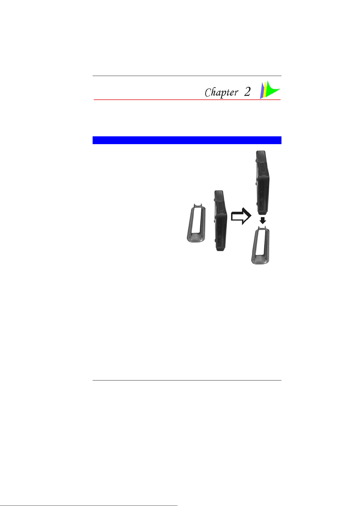
W
ORKING ROOM SCENARIO
In using the Mini PC in your own private study room, place it
together with LCD monitor, speakers, printer/scanner/fax, modem
or any other peripherals.
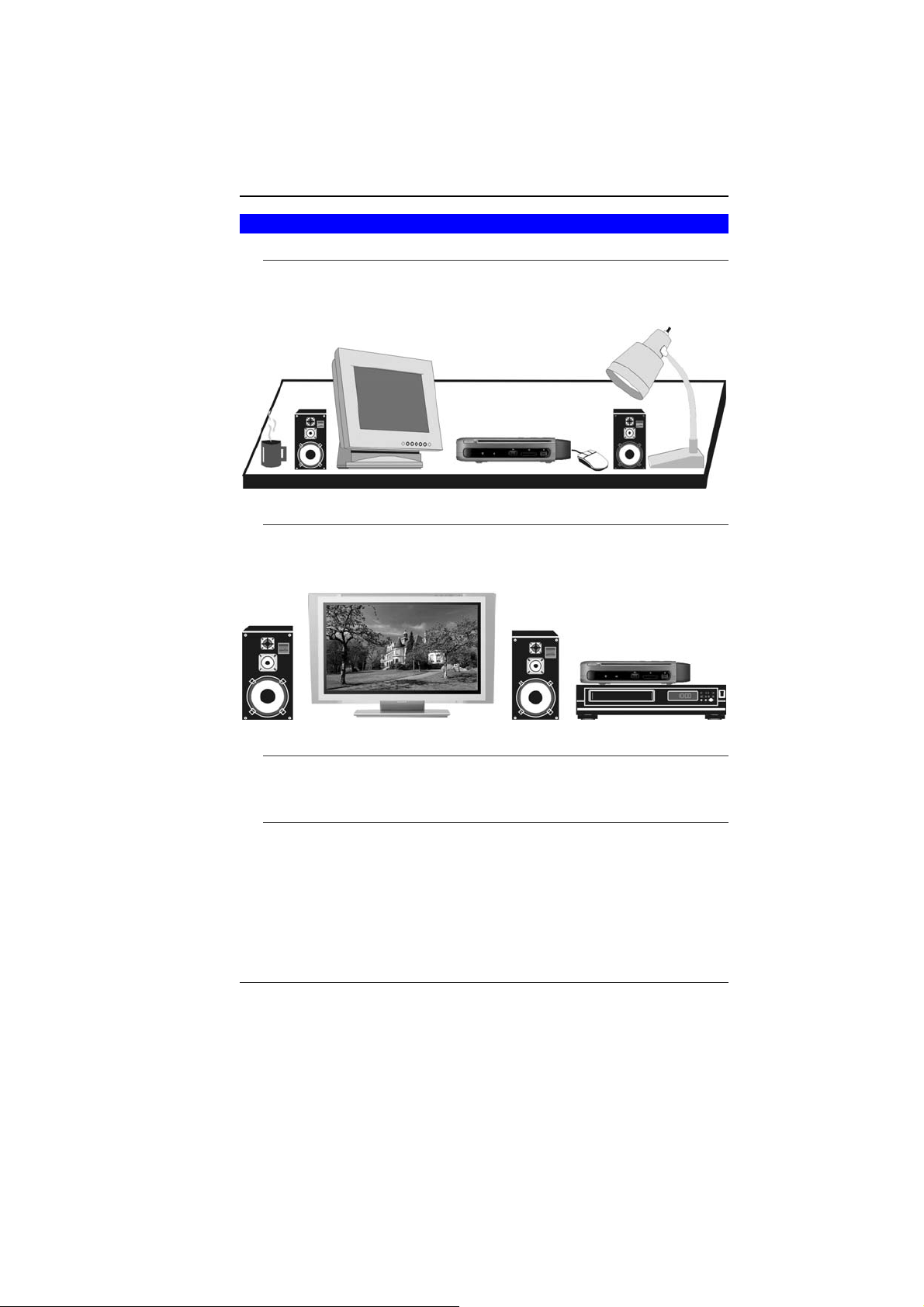
LIVING ROOM SCENARIO
In using the Mini PC in your own living room, connect it to a
speaker, HDTV, DVD/VCD player, modem or any other peripherals
in building your own media center at home.
OFFICE SCENARIO
You can also connect the Mini PC to a projector to make a
presentation in a business conference.
BUSINESS TRIP SCENARIO
Because of being a handy computer, you can carry the media
center pc with you on your business trip since it can be
conveniently keep in a hand bag.
6
Page 19
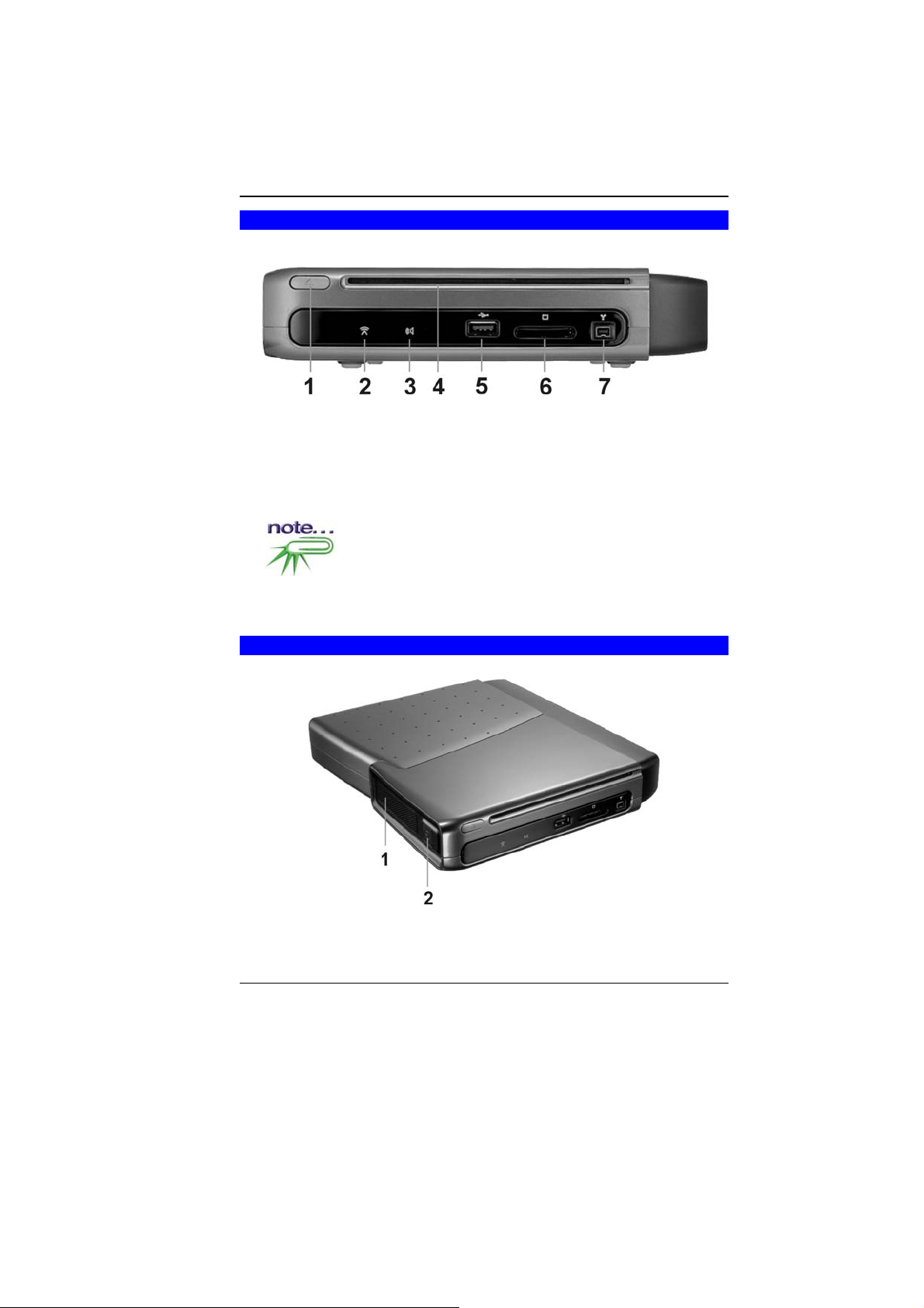
FRONT SIDE FEATURES
CD-ROM Release Latch
11..
Wireless LED
22..
MCE Sensor
33..
Combo Drive/DVD-Dual/DVD Super-Multi
44..
USB 2.0 Port
55..
CardReader (MMC/SD/MS)
66..
Be sure the face of the card must be facing down when
inserting without using the stand or bottom side facing you when
inserting using the stand.
1394A
77..
TOP SIDE FEATURES
Ventilation Opening
11..
Power Button
22..
7
Page 20
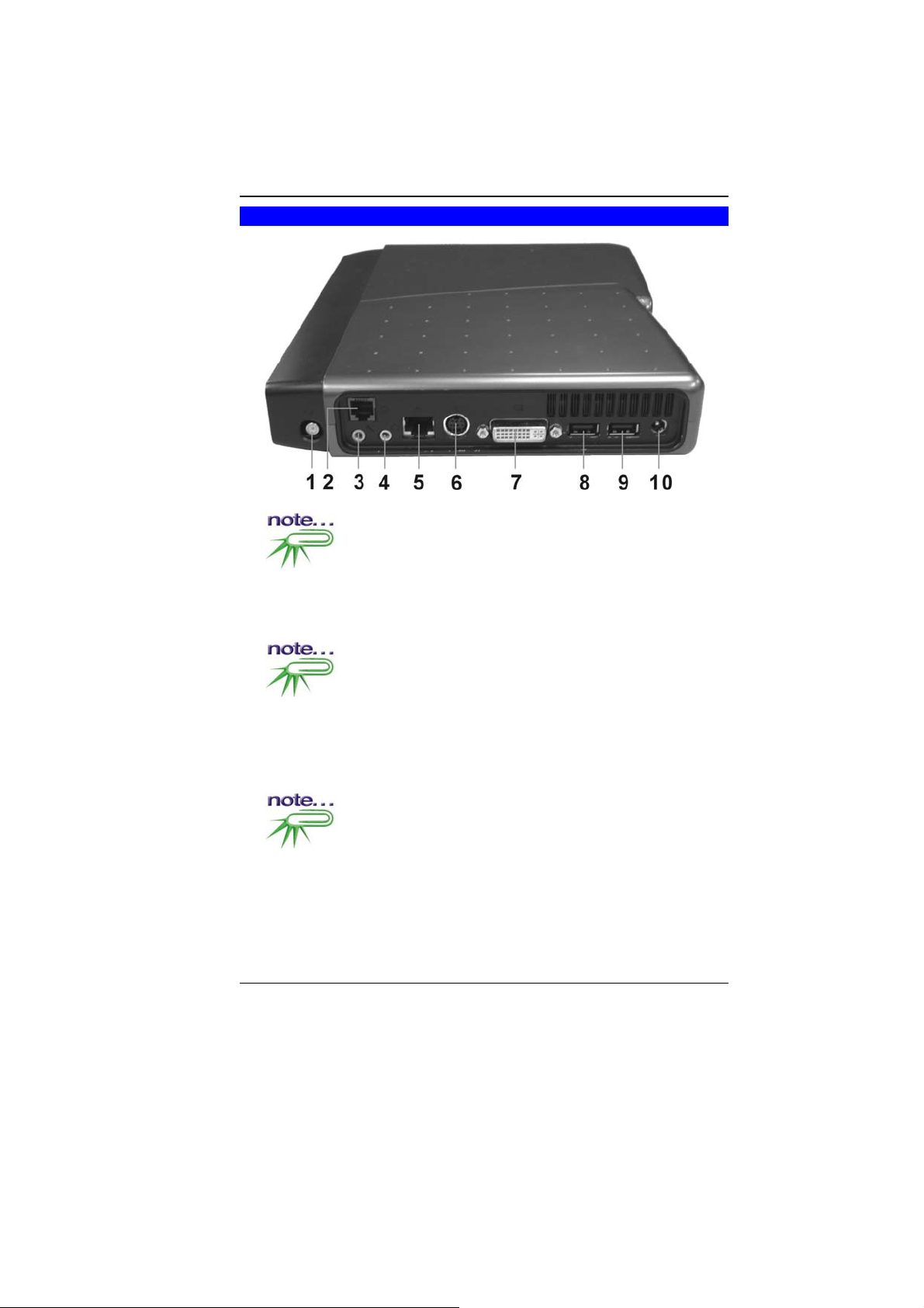
REAR SIDE FEATURES
Digital/Cable TV Connector
11..
Before connecting the cable into the connector one thing
that you need to be aware of is to know the video standard being
used in your country that you are viewing. This system supports 3
video standard namely: NTSC, PAL and SECAM or DVBT (Optional).
Modem Port
22..
Always disconnect all telephone lines from the wall outlet
before servicing or disassembling this equipment. To reduce the risk
of fire use only No. 26 AWG or larger telecommunication line cord.
Microphone Jack
33..
Earphone Jack
44..
LAN Connector
55..
When using a LAN, please use an EMI Shielding Cable to
minimize an inteference when transmitting.
S-Video/Composite Port
66..
8
Page 21
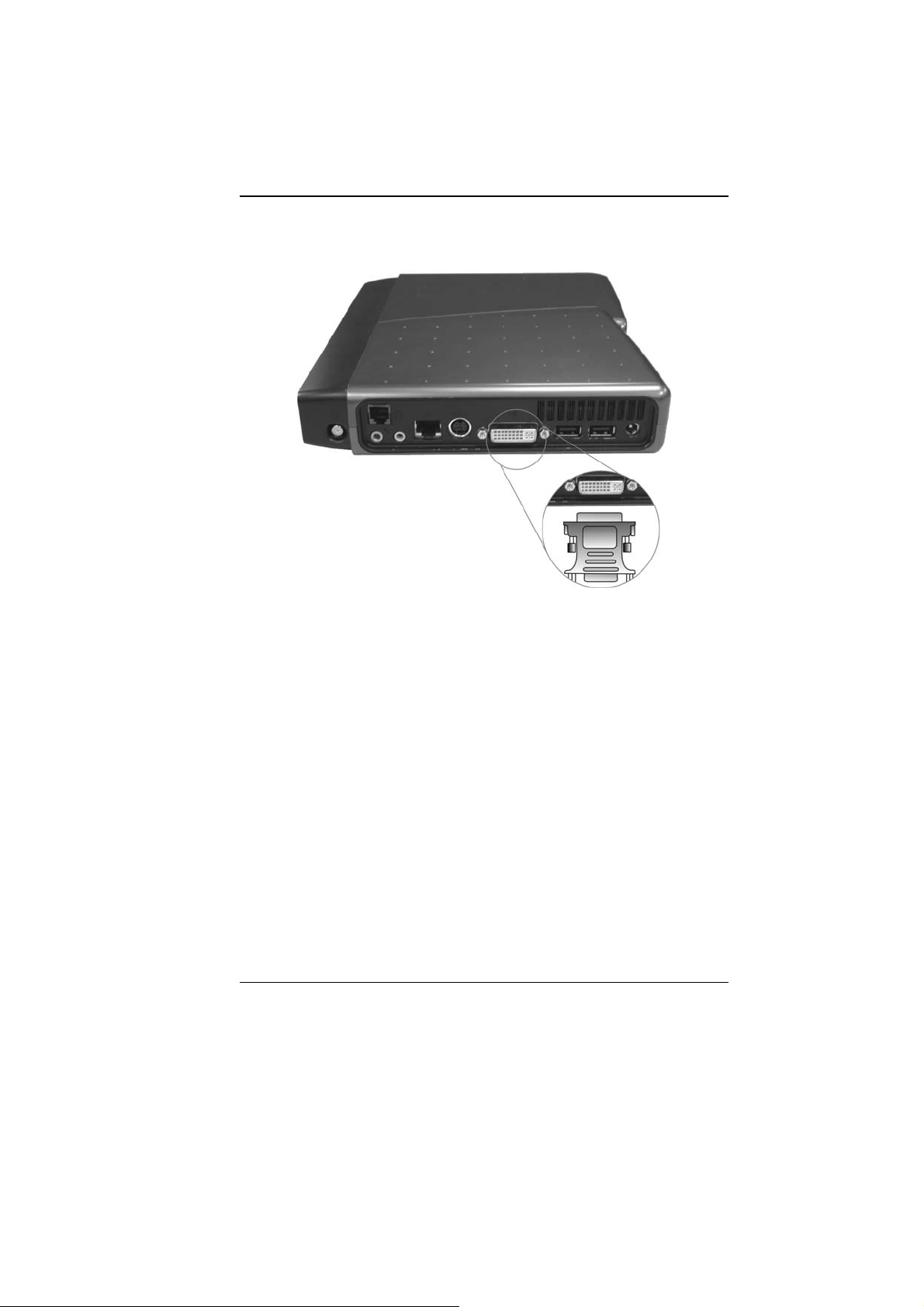
DVI (Digital Video Interface) Connector
77..
DVI is a digital interface standard to convert analog signals into
digital signals to accommodate both analog and digital monito rs.
USB 2.0 Port
88..
USB 2.0 Port
99..
DC-In Connector
1100..
9
Page 22

Page intentionally left blank
10
Page 23

Getting Started
CONNECTING TO A POWER SOURCE
A universal AC adapter is provided to supply your computer with
power. The adapter’s AC input voltage can range anywhere from
100 to 240 volts, covering the standard voltages available in
almost every country. The power cord for the AC adapter requires
a three-hole grounded AC outlet. To connect the computer to an
external power source:
Do not use inferior extension cords as this may
result in damage to your computer. The computer comes with its
own AC adapter. Do not use a different adapter to power the
computer and other electrical devices.
11
Page 24

Never turn off or reset or move your comptuer while
the hard disk is in use; doing so can result in loss or destruction of
your data. Always wait at least 5 seconds after turning off your
computer before turning it back on; turning the power on and off in
rapid succession can damage the computer’s electrical circu itry.
POWERING UP THE MINI PC
At the top of the Mini PC, locate on the power button and press for
a few seconds to power up the system. The Power-On Self Test
(POST) runs automatically.
After the POST is completed, the computer reads the operating
system from the hard disk drive into computer memory (this is
commonly referred to as “booting” a computer). If your OS
(Operating System such as Windows XP…. etc) is installed, it
should start automatically.
To turn the computer off, save your work and close all open
applications, click on Start, then Shu
down the computer and click "Y
4-6 seconds. (abnormal shutdown)
t Down and select Shut
es" or press the power button for
POWER SAVING MODES
This section contains information on the Mini PC power system
and tips for conserving power.
The AC Adapter converts AC power from a wall outlet to the DC
power required by the computer.
The system provides you with a new power function “Intel Quick
Resume Technology” for you to utilize a power saving scheme.
12
Page 25

From the Control Panel, select and click on the “Power Options” to
enter the Power Options Properties” display.
Notice that there are four items namely: Power Schemes, Advanced,
Hibernate, and UPS.
After the installation of the driver for this system is completed, you
will notice the “Away” item is added into “Power Options
Properties”.
In case the item is not included, we recommend you to install the
driver using the support CD that comes with your system. Proceed
to “Driver\QuickResume\el.all.exe to install the driver.
Enable “Away Mode”
^ Press the Power button will enter the (Away) power saving
mode (orange color)
13
Page 26

^ A slight move on the keyboard or mouse will enter the
resume mode (blue color)
14
Page 27

Using the Mini PC
CONNECTING YOUR SYSTEM
V
IDEO DISPLAY CONNECTION
The system enables you to connect the system to different types of
video display devices, like projector, LCD or traditional monitor
(CRT), or TV unit.
LCD OR CRT MONITOR CONNECTION
You can connect the system to different types of LCD monitor. The
video signal connector from the LCD monitor connects to the DVI
connector through a DVI cable.
HDTV SET CONNECTION
You can connect the system to an external HDTV through the DVI
connector at the rear through a DVI cable.
CONVENTIONAL TV SET CONNECTION
You can connect a conventional TV using an “S-Video to SVideo/YPbPr/Composite Video” cable to the S-Video connector of
the system.
KEYBOARD AND MOUSE CONNECTION
You can connect the keyboard and mouse to the USB connectors.
EXPANDING THE SYSTEM
The system provides you with three USB connectors with one on
the front and two at the rear conveniently for you to add some
external peripherals.
In case you have no additional USB connectors to connect other
USB peripherals, try installing an optional “expander” box or an
USB hub for system expansion.
15
Page 28

PRINTER CONNECTION
You can connect the system to a USB printer.
FAX/PRINTER/SCANNER CONNECTION
Today’s manufacturers build the functions of printer, scanner, and
fax into one unit so you connect the system to a fax/printer/scanner
unit if it comes with a USB connector.
SPEAKER CONNECTION
The input of the speaker should be connected to the speaker
output (earphone) jack.
WEB CAMERA CONNECTION
Today’s technology provides users more convenient way to
communicate with their friends and family using the internet for
instant messaging.
After you have installed a web camera, install the software driver
for the web camera, and set up your instant messaging account
properly, you will be able to see the person you are chatting
through the internet.
MEMORY STICKS, CARD READERS, MEMORY CARDS
CONNECTION
Through these memory cards, you can copy files from another PC
to your system. There are numerous varieties of memory devices
that you can use copying files from another PC.
16
Page 29

17
Page 30

THE COMBO DRIVE/DVD-DUAL/DVD SUPER-MULTI
EATURES OF THE COMBO DRIVE/DVD-DUAL/DVD SUPER-
F
M
ULTI
The features of the Combo Drive/DVD-Dual/DVD Super-Multi drive
are listed below.
^ The Audio Play feature allows you to play music CDs
^ Front panel load/unload button
^ Supports CD-DA, CD-ROM mode 1 and mode 2, Multi-
Session Photo CD™, CD-I/Video CD (pcs.)
^ Low power consumption
^ 12.7mm height
PRECAUTIONS FOR HANDLING COMBO DRIVE/DVD-DUAL/DVD
SUPER-MULTI DISCS
^ Always hold the disc by the edges, avoid touching the surface.
^ Use a clean, dry, cloth to remove dust, smudges, or
fingerprints. Wipe from the center outward.
^ Do not write or place objects on the surface of the disc.
^ Store discs in a cool dry place not to damage the disc.
18
Page 31

^ Do not use benzene, thinners, or cleaners with detergent.
Only use CD-ROM/DVD-ROM cleaning kits.
^ Do not bend or drop the discs.
LOADING A DISC
To play a CD disc, follow the instructions listed below.
1. Push the Combo Drive/DVD-Dual/DVD Super-Multi button on
the CD drive door. Gently pull the tray all the way out.
2. Carefully lift the CD disc by the edges and make sure the
shiny surface is face down (the side with no writing on it).
Carefully insert the CD disc onto the tray. Push the CD disc
down gently so that it snaps onto the center ring.
3. Push the tray back into the drive.
To remove a CD disc, do the following:
1. Check the LED display and make sure that the computer is not
accessing the Combo Drive/DVD-Dual/DVD Super-Multi.
2. Push the eject button and pull the tray all the way out.
3. Carefully pick up the CD disc by the edges and – while
pressing down on the center ring – remove the CD disc from
the tray.
USING THE WINDOWS
ELP WINDOWS
H
For Windows XP help, click Start ÎHelp and Support icon will
open the dialog box.
19
Page 32

DESKTOP
Desktop may vary differently on the software installed in your
computer with different or additional shortcuts.
Recycle Bin
Used for storing deleted files in case you want to recover and save
it in your system. The files will only be deleted from the Recycle
Bin permanently only if you empty it by right clicking your mouse
and select the “Empty Recycle Bin”.
Start Button
Allows easy access to all Windows programs.
The Start menu allows you to
adapt and show the
programs used most
frequently. If you wish to
keep an item, right click the
item and click Pin to Start
menu.
Log Off will enable the
current user to log off and
allows a new user to log on.
Turn Off Computer allows
you to shut down, restart,
and Stand by modes for
power saving purposes.
20
Page 33

Taskbar
When you open a program, its icon is displayed at the taskbar for
you to conveniently move between programs by clicking the
relevant button.
To add or remove toolbars from the taskbar: right click an empty
spot on the taskbar, select Toolbars Î choose the toolbar you
want to a d d.
Notification
The icons that appear here are for quick access to some programs
and computer functions that you frequently used. For you to see
the hidden icons, simply click the
icon.
To prevent Windows XP from hiding icons:
From an empty spot on the Taskbar, right click your mouse and
select the Properties, remove the checked mark on the Hide
inactive icons.
CONTROL PANEL
It is in this area that you can change how Windows looks and
works. Click Start Î Control Panel dialog box. There are two
interfaces – Classic View or Category View.
21
Page 34

22
Page 35

Internet Connection
There are numerous ways to connect to the Internet. This may vary
from the user’s working environment as well as system
specifications.
^ Using a modem and a telephone line
^ Using a wired LAN
^ Using a wireless LAN (Optional)
USING A MODEM FOR CONNECTION TO INTERNET
^ Use a telephone line to connect to the modem port of your
computer. Do not use a digital telephone line.
^ Please apply to an Internet Service Provider (ISP) for
Internet service in order for you to connect the modem to the
Internet and use e-mail.
For more detail on the Network key, please refer to your
local ISP provider and follow the procedures describe in the “ISP
Installation Guide” to proceed with the installation.
USING A WIRED LAN FOR CONNECTION TO INTERNET
For you connect to the Internet, a wired LAN environment normally
uses the company’s LAN or a broadband modem.
1. Use the network (LAN) cable to connect to the LAN port of the
system.
2. Select on “My Network Places” and click on the “View Network
Connection” in the “Control Panel” window.
3. In the “Network Tasks” window, use your mouse pointer to
click on the “Local Area Connection”.
23
Page 36

4. Select “Properties” from the popup menu that appears
5. In the “This connection uses the following items” field, select
“Internet Protocol (TCP/IP), and click “Properties”.
24
Page 37

6. Enter the system’s IP and DNS server addresses on the
General tab of the “Internet Protocol (TCP/IP) Properties”
window. If DHCP is used, click “Obtain an IP address
automatically” and “Obtain DNS server address automatically”
on the General tab.
25
Page 38

7. After all the all the information are correctly entered in the
“Internet Protocol (TCP/IP) Properties” window, click “OK” to
finish.
USING BOTH DHCP AND STATIC IP FOR CONNECTION TO
INTERNET
When you are alternatively using networks with either DHCP or
static IP addressing, you can use alternative settings that enable
simultaneous configurations of DHCP and static IP to use both of
the network connects without reconfiguring.
1. Follow the steps mentioned when you are using wired LAN
connection from 1 to 7.
2. Click on the “User configured” and enter the appropriate
values in the “Alternate Configuration” tab.
26
Page 39

3. When you have completed the entire configuration, click “OK”.
27
Page 40

USING WIRELESS LAN NETWORK FOR CONNECTION TO INTERNET
(MICROSOFT’S SERVICE PACK 2) (OPTIONAL)
BLUETOOTH CONNECTION
Bluetooth is a developing, world wide, open, short-range radio
specification focused on communication between the Internet and
Net devices, plus it defines communication protocols between
devices and computers.
It connect wirelessly to your world: In home, at work, in motion and
at play.
Access the internet or your e-mail account from anywhere, anytime.
Fast downloads.
28
Page 41

Press on the Bluetooth icon to connect other devices that
have this application.
29
Page 42

Page intentionally left blank
30
Page 43

Running BIOS Setup
The BIOS (Basic Input and Output System) Setup program is a
menu driven utility that enables you to make changes to the
system configuration and tailor your system to reflect installed
hardware or alter system performance. When the computer is
turned back on, the system is configured with the values stored in
CMOS. With easy-to-use menus, you can configure such items as:
^ Hard drives and peripherals
^ Boot up Drive Sequence
^ Password protection
The settings made in the BIOS Setup program intimately affect
how the computer performs.
NAVIGATING THROUGH BIOS SETUP
The Setup program has been designed to make it as easy to use
as possible. If you accidentally make a setting and don’t know
which one to switch back to, the Setup program has a hot key that
allows you to return to the previous value.
ACCESSING THE BIOS SETUP PROGRAM
To access the BIOS Setup program, press the DEL key after the
computer has run through its POST.
You can not use a Bluetooth keyboard under the DOS environment.
ITEM SPECIFIC HELP
On the right side of the Setup screen is an area labeled Item
Specific Help. This area will list navigation key shortcuts and
information that is specific for the item that you are currently editing.
31
Page 44

THE MENU BAR
The top of the screen has a menu bar with the following selections:
Main - Use this menu to make changes to the basic system
configuration.
Advanced - Use this menu to enable and make changes to the
advanced features available on your system.
Security - Use this menu to set a password. The password allows
bootup and controls access to the BIOS setup menu.
Boot - Use this menu to configure the default system device used
to locate and load the Operating System and for booting up the
computer.
Exit - Use this menu to exit the current menu or specify how to exit
the Setup program.
To access the menu bar items, press the right or left arrow key on
the keyboard until the desired item is highlighted.
THE LEGEND BAR
At the bottom of the Setup screen you will notice a legend bar. The
keys in the legend bar allow you to navigate through the various
setup menus. The following table lists the keys found in the legend
bar with their corresponding alternates and functions.
Legend
Key
F1 Displays the General Help window. It can
Esc Jumps to the Exit menu or returns to the
←
→
↑ or ↓
Tab Enter Moves the cursor to the next position
Minus
key (-)
Plus key
(+)
Home PgUp Moves the cursor to the field at the top of the
End PgDn Moves the cursor to the field at the bottom of
Alternate
Key
be enabled from anywhere in the BIOS.
Main menu from a submenu.
Selects the menu item to the left.
Selects the menu item to the right.
Keypad
arrow keys
Scrolls backward through the values for the
Scrolls forward through the values for the
Moves the cursor up and down between
fields.
available in the field.
highlighted field.
highlighted field.
window.
the window.
Function
32
Page 45

F9 Sets the parameters for the current menu to
their default values.
F10 Save and Exit.
Enter Will select a sub menu or show a range of
options for a field.
LAUNCHING SUBMENUS
Note that a right pointer symbol X appears to the left of certain
fields. This pointer indicates that a submenu can be launched from
this field. A submenu contains additional options for a field
parameter. To call up a submenu, simply move the cursor to
highlight the field and press the [Enter] key. Use the [Esc] key to
return to the Main menu.
GENERAL HELP
In addition to the Item Specific Help window, the BIOS Setup
program also provides a General Help screen can be called up
from any menu by simply pressing [F1]. Use the [PgUp] and [PgDn]
keys or the up and down arrow keys (↑↓) to scroll through the
entire help document.
Press the Home key to display the first page, press End to go to
the last page. To exit the help window, press the [Enter] or the
[Esc] key.
Save Changes and Exit the Setup Program
Refer to the Exit menu section of this chapter for detailed
information on saving changes and exiting the setup program.
33
Page 46

THE MAIN MENU
When the Setup program is accessed, the following screen
appears:
34
Page 47

THE ADVANCED MENU
Selecting Advanced from the menu bar displays the Advanced
menu:
35
Page 48

THE BOOT MENU
The Boot menu allows the user to specify the order in which the
computer is to check for a device to boot the system. You can also
configure the way that the system will boot up.
To make changes, select Boot from the menu bar. The following
screen appears:
36
Page 49

THE SECURITY MENU
The computer’s advanced system of security allows you to set a
password to prevent unauthorized access to system resources,
data, and the BIOS Setup Program.
37
Page 50

THE EXIT MENU
Once you have made all of your selections from the various menus
in the Setup program, you should save your changes and exit
Setup. Select Exit from the menu bar to display the following menu:
38
Page 51

VGA Utilities
After you have restarted Windows, open the “Control Panel” and
double click on the “Display” icon. From the “Display Properties”
window, select the “Settings” tab and click on the “Advanced” tab
to enter the “Plug and Play Monitor on Mobile Intel® 945GM
Express Chipset Family”.
39
Page 52

40
Page 53

OVERLAY SETTINGS
41
Page 54

LAUNCH ZOOM
42
Page 55

DISPLAY DEVICES
You can adjust the right resolution for your screen display.
43
Page 56

DISPLAY SETTINGS
44
Page 57

COLOR CORRECTION
45
Page 58

HOT KEYS
The driver allows simultaneous outputs to CRT and TV. Before
proceeding, be sure the monitor and TV are connected to the
computer.
There are three default values namely:
^ Enable Television - <CTRL><ALT>F2
^ Enabled Digital Display - <CTRL><ALT>F4
^ Open Graphics Property Application - <CTRL><ALT>F12
To select an item, just point the cursor on any of the three default
values at the Hot Keys column according to the type of peripherals
that you would like to display and right click your mouse button.
The “Select Hot Key Combination” display window will be displayed
on your screen as illustrated below:
46
Page 59

Select any key or function to replace the default key of F2 and click
the “OK” button.
Example: Type F8 to replace the current function key of F2 from
the default mode.
The result is from:
<CTRL><ALT>F2 (previous) Î<CTRL><A LT>F8 (after)
47
Page 60

Page intentionally left blank
48
Page 61

Microsoft Center Edition
(MCE) (Option)
WINDOWS XP MEDIA CENTER EDITION (MCE)
The Windows MCE is a complete software for home PC operating
system for you to enjoy entertainment choices together in one
place easily accessible from anywhere in the room. This will
benefits the consumers to enjoy Media Center experience in their
own living room.
For more information on the function of the MCE, please refer to the
Microsoft’s Windows XP MCE user’s guide that goes along with your
software package.
49
Page 62

50
Page 63

Installing the WinXP (MCE)
in AHCI System
WINXP MCE INSTALLATION
1. Before proceeding, restart your computer and press the “DEL”
key to enter the BIOS Setup.
2. Proceed to “Advanced” Setup using the Î arrow and select
the “IDE Configuration item.
3. Set the BIOS setup IDE mode to “ATA/IDE Configuration
[Enhanced] and Configure SATA as [AHCI] mode.
51
Page 64

4. Put your floppy disk into the USB FDD drive that contain AHCI
driver. (i.e.: Windows setup don’t support USB disk).
5. Now you can start installing the WinXP MCE in AHCI mode.
6. Press the “F6” key to load the AHCI Driver
7. Press the “S” key in specifying to install the device for your
system.
52
Page 65

8. Select the “Intel ® 82801GBM SATA AHCI Controller (Mobile
ICH7M)”.
9. The selected device will now display on the screen.
53
Page 66

10. After installing the AHCI driver, the AHCI HDD (Mass Storage
Device) is now displayed.
11. You can now follow the WinXP MCE installation process to
install the Operating system.
If your WinXP MCE CD still include the old IDE driver (e.g. Intel 915
Chipset or other), you will not be able to install the OS (like having
blue screen or system restart). We recommend you to contact your
WinXP MCE OPK CD engineer to remove the old driver and replace
with a new one.
54
Page 67

Troubleshooting
This chapter describes locating and solving problems that you may
encounter while using your computer.
CHECKING CABLES AN D CONNECTIONS
Start by performing a careful visual inspection of the exterior of the
computer. If no LEDs are illuminated, make sure that your
computer and its peripherals are getting power and communicating
with each other properly.
To check the power cables, and connections:
1. If you are using the computer with the AC adapter, check the
power outlet, the power cord, and any power switches that
may affect your computer.
2. Check the wall outlet or power strip with an item that you know
is functioning properly. A lamp or radio is a convenient item for
checking the power. You may also need to check the fuses
and breakers in your electric box.
3. If the outlet is controlled by a wall switch, make sure that the
switch is on.
4. If the outlet is controlled by a dimmer switch, use a different
outlet.
5. If your computer is plugged into a power strip with an On/Off
switch, make sure the switch is on.
6. With the computer’s power switched off, check all cable
connections. If the computer is connected to any peripheral
devices, look for loose or disconnected cables.
If the computer is too close to a wall, a cable connection may be
loose or the cables may be crimped.
55
Page 68

Do not substitute cables for different devices (other than
the manufacturer recommended cables) even if they look exactly
alike. The wiring inside the cable may be different.
7. When you are certain that you have power available and all
connections are good, turn the computer on again. If the
computer still does not start, you may have a hardware
problem.
GENERAL PROBLEMS
A few common hardware problems and suggested solutions are
presented below:
Question: The speakers, keyboard, mouse does not work after
connecting the peripherals to the system unit.
Answer: Be sure that the peripherals are conne cted correctly
to their respective connectors. Check if it is
connected loosely. Power up the system once again
and see to it if the system works properly. If the
speakers and monitors does not work, please refer
to their respective manuals that comes with the
peripheral for troubleshooting.
Question: After installing all the drivers and peripherals and the
system does not work, what should I do?
Answer: Please try to consult your authorized dealer or
maintenance service personnel. We strongly advice
you not to fix the system by yourself since it might
cause damage to the system.
56
Page 69

Specification
DETAILED SPECIFICATIONS
Processor
^ Intel® Yonah Duo/Solo Core, 2MB L2 Cache, up to 66 7MHz
FSB
^ Micro-FCPGA 478 socket
Operating System Compliance
^ Microsoft
^ Microsoft
^ Microsoft
Core Logic
^ Intel 945GT + ICH7-M (DH)
Memory
^ Dual channel DDRII 533/667, memory support DMI 2GB/s
link with south bridge
^ Expandable 2 slot of 200pin SO-DIMM module, 2B total
memory capacity
Video & Graphics
^ Intel 945GT internal graphics
^ Intel Gen 3.5 Integrated Graphics Engine
^ HDTV support 480p/720p/1080i/1080p
Hard Drive
^ SATA HDD supported
Optical Drive
^ 5.25” 12.7mm height Combo Drive/DVD-Dual/DVD Super-
Multi
EC Controller
^ ENE KB3910
®
Windows® XP Media Center Edition
®
Windows® XP Home/ Professional Edition
®
Windows® XP Home Edition
57
Page 70

LED Status Indicator
^ Power, WLAN
Interface Ports
^ S-video TV out port, DC input port for External AC adapter
(2-pin DC jack), DVI-I port for external analog VGA monitor
& external Digital monitor, USB 2.0 port*3, MIC-In,
headphone jack w/ adapter for 5.1 channel SPDIF support,
Fax/Modem (internal MDC module), GigaLAN port, IEEE
1394 mini-jack, Card Reader, SDVO DVI 1.0 support for
External Digital Monitor
Built-in TV Tuner
^ Mini PCI TV Tuner with Coaxial connector, support PAL,
NTSC, SECAM or DVBT (Optional)
Audio
^ Integrated Audio
^ High definition Audio Code c
^ Support SPDIF out
AC Adapter
^ External universal type AC adapter, output maximum 65W
Communication
^ Intel Pro/Wireless 3945ABG Mini-PCIE or Intel Pro/Wireless
3945 B+G Mini-PCIE interface
^ Intel Giga LAN
^ Built-in MDC modem or Built-in MDC modem + Bluetooth
combo module, (V.92/56K + Blue core 1.2)
Dimension
^ 230(L) x 197.5(W) x 42(H) mm
Weight
^ System Weight: 1.365kg
^ Base Stand Weight: 0.159kg
58
 Loading...