

Page 1

i
Preface
Copyright
This publication, including all photographs, illustrations and software, is protected
under international copyright laws, with all rights reserved. Neither this manual, nor
any of the material contained herein, may be reproduced without written consent of
the author.
Version 2.2
Disclaimer
The information in this document is subject to change without notice. The manufacturer makes no representations or warranties with respect to the contents hereof and
specifically disclaims any implied warranties of merchantability or fitness for any
particular purpose. The manufacturer reserves the right to revise this publication and
to make changes from time to time in the content hereof without obligation of the
manufacturer to notify any person of such revision or changes.
Trademark Recognition
Windows® 7/8 are registered trademarks of Microsoft Corp.
Other product names used in this manual are the properties of their respective
owners and are acknowledged.
Federal Communications Commission (FCC)
This equipment has been tested and found to comply with the limits for a Class B
digital device, pursuant to Part 15 of the FCC Rules. These limits are designed to
provide reasonable protection against harmful interference in a residential installation. This equipment generates, uses, and can radiate radio frequency energy and, if
not installed and used in accordance with the instructions, may cause harmful interference to radio communications. However, there is no guarantee that interference
will not occur in a particular installation. If this equipment does cause harmful
interference to radio or television reception, which can be determined by turning the
equipment off and on, the user is encouraged to try to correct the interference by one
or more of the following measures:
• Reorient or relocate the receiving antenna
• Increase the separation between the equipment and the receiver
• Connect the equipment onto an outlet on a circuit different from that to
which the receiver is connected
• Consult the dealer or an experienced radio/TV technician for help
Shielded interconnect cables and a shielded AC power cable must be employed with
this equipment to ensure compliance with the pertinent RF emission limits governing this device. Changes or modifications not expressly approved by the system’s
manufacturer could void the user’s authority to operate the equipment.
Preface
Page 2

ii
Declaration of Conformity
This device complies with part 15 of the FCC rules. Operation is subject to the
following conditions:
• This device may not cause harmful interference, and
• This device must accept any interference received, including interference that may cause undesired operation
Canadian Department of Communications
This class B digital apparatus meets all requirements of the Canadian Interferencecausing Equipment Regulations.
Cet appareil numérique de la classe B respecte toutes les exigences du Réglement sur
le matériel brouilieur du Canada.
Preface
Page 3

iii
Safety Instructions
Your system is designed and tested to meet the latest standards of safety for information technology equipment. However, to ensure your safety, it is important that you
read the following safety instructions.
Setting up your system
• Read and follow all instructions in the documentation before you operate your system.
• Do not use this product near water or a heated source such as a
radiator.
• Set up the system on a stable surface.
• Openings on the chassis are for ventilation. Do not block or cover these
openings. Make sure you leave plenty of space around the system for
ventilation. Never insert objects of any kind into the ventilation openings.
• Use this product in environments with ambient temperatures between
0°C and 40°C.
• If you use an extension cord, make sure that the total ampere rating of
the devices plugged into the extension cord does not exceed its ampere rating.
Attention during use
• Do not step on the power cord or let anything rest on top of it.
• Do not spill water or any other liquid on your system.
• When the system is turned OFF, a small amount of electrical current still
flows. Always unplug all power, modem, and network cables from the
power outlets before cleaning the system.
• If you encounter the following technical problems with the product,
unplug the power cord and contact a qualified service technician or
your retailer.
• The power cord or plug is damaged.
• Liquid has been spilled into the system.
• The system does not function properly even if you follow the
operating instructions.
• The system was dropped or the cabinet is damaged.
• The system performance changes
The warranty does not apply to products that have been disassembled by
users
Preface
Page 4

iv
Safety cautions and warnings
Optical Drive Safety Information
Optical drive sold with this system contains a CLASS 1 LASER PRODUCT.
CAUTION:
Invisible laser radiation when open. Do not stare into beam or view
directly with optical instructions.
WARNING:
Makeing adjustments or performing procedures other than those speci-
fied in the user’s manual may result in hazardous laser exposuer. Do
not attempt to disassemble the optical drive. For your safety, have the
optical drive serviced only by an authorized service provider.
Product disposal notice
INPORTANT:
This symbol if the crossed out wheeled bin indicates that the product
(electrical and electronic equipment) should not be placed in municipal waste. Check local regulations for disposal of electronic products.
Nordic Lithium Cautions (for lithium-ion batteries)
CAUTION:
Danger of explosoin if battery is incorrectly replace only with the same
or equivalent type recommended by the manufacturer. Dispose of used
batteries according to the manufacturer’s instructions.
Product disposal notice
1. Do not place this product underneath heavy loads or in an unstable
position.
2. Do not use or expose this product around magnetic fields as magnetic interference may affect the performance of the product.
3. Do not expose this product to high levels of direct sunlight, highhumidity or wet conditions.
4. Do not block the air vents to this product or impede the airflow in
any way.
Preface
Page 5

TT
ABLE OF CONTENTSABLE OF CONTENTS
T
ABLE OF CONTENTS
TT
ABLE OF CONTENTSABLE OF CONTENTS
Preface i
Chapter 1 1
Introducing the PC 1
Introduction......................................................................................1
Specification......................................................................................2
Front and Rear I/O............................................................................3
Packing Contents..............................................................................5
v
Chapter 2
Installing the PC 7
System Quick Installing...................................................................7
Chapter 3 11
Using BIOS 11
About the Setup Utility................................................................ 1 1
The Standard Configuration..............................................11
Entering the Setup Utility....................................................1 1
Resetting the Default CMOS V alues...................................12
Using BIOS......................................................................................12
BIOS Navigation Keys.......................................................13
Main Menu .......................................................................13
Advanced Menu.................................................................14
Chipset Menu.....................................................................24
Freq/Volt Control Menu.....................................................27
Boot Menu..........................................................................31
Security Menu....................................................................33
Exit Menu...........................................................................36
Updating the BIOS.............................................................37
Chapter 4
Using the Software 39
About the Software DVD-ROM/CD-ROM..................................39
Auto-installing under W indows 7/8.............................................39
Running Setup....................................................................40
Manual Installation.........................................................................42
Utility Software Reference.............................................................42
7 7
7
7 7
39 39
39
39 39
Page 6

vi
Chapter 5
T r ouble Shooting 43
Start up problems during assembly...............................................43
Start up problems after prolong use............................................44
Maintenance and care tips............................................................44
Basic Troubleshooting Flowchart................................................45
4343
43
4343
Page 7
Chapter 1
Introducing the PC
Introduction
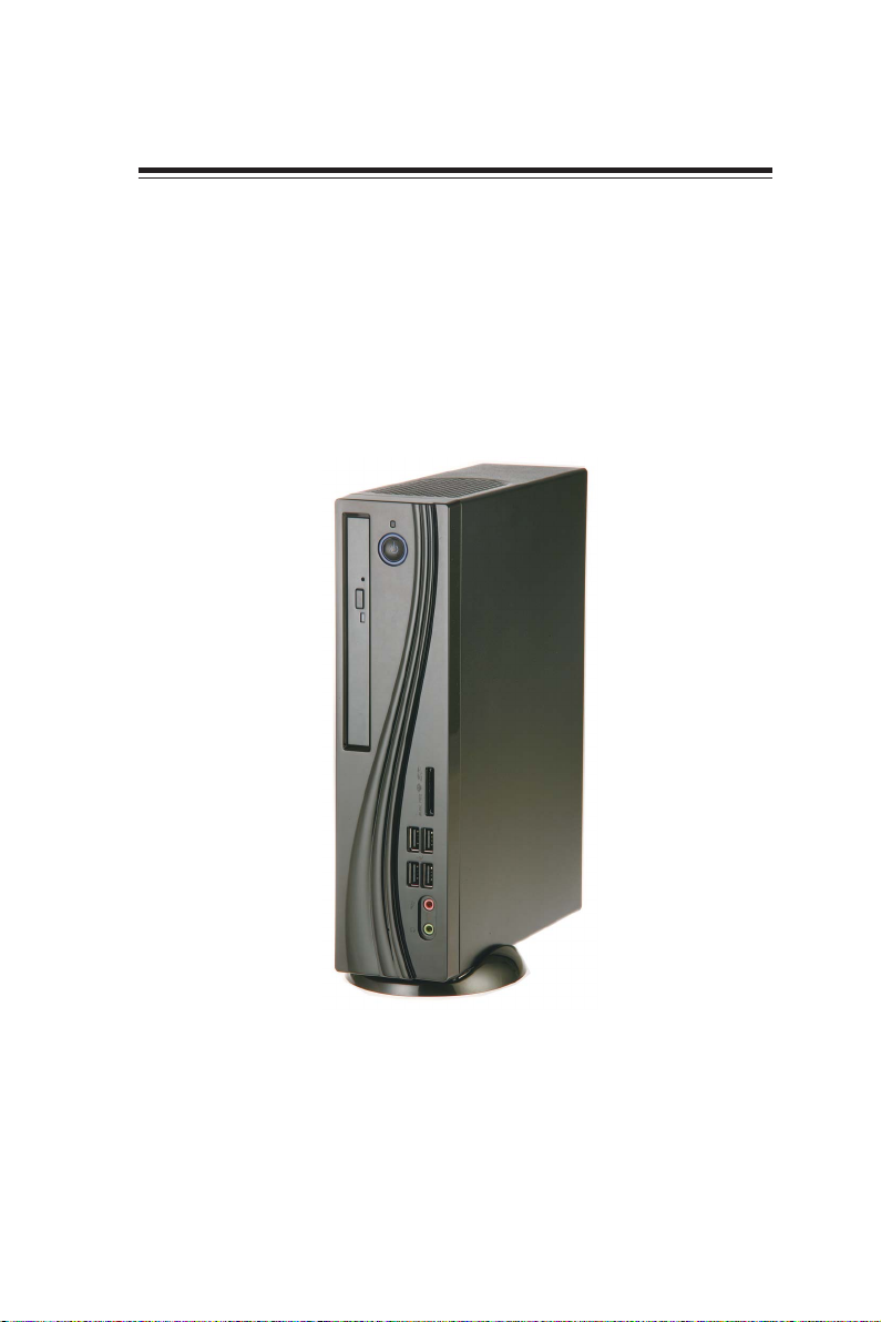
Thank you for choosing 3.8L MS300 of great performance and with stylish and
flexible design.
® 2nd/3rd
Supports LGA1155 Socket for Intel
dimension of 270mm (H)* 205mm (D)* 70mm (W), 3.8L SFF provides the features
of low power consumption (working with a 120Watt power adaptor), and space
saving. The chipset is Intel® H61, supporting up to 8 GB of system memory with
DDR3 memory SO-DIMM, 3.5” SATA II HDD, SATA II Slim DVD Super-multi
Tray type, and Build in Intel® HD Graphics.
Generation CoreTM processors and a
1
Note:
ID design may vary.
Introducing the PC
Page 8

2
Specification
Chipset
CPU Support
Memory
Graphics
Storage
ODD
Front Panel
Rear Panel
Power
OS Support
Expansion
Dimensions (mm)
• Intel
• Supports LGA1155 Socket for Intel
®
H61
® 2nd/3rd
Generation
CoreTM processors (up to 65W)
• 2 x SO-DIMM up to 8 GB, Dual-channel
• Intel
®
HD graphics from CPU
• Support Full HD Playback and DX10.1 for Sandy Bridge,
DX11 for Ivy Bridge
• Support 1 x 3.5” SATA II HD D
• Support SATA II Slim DVD Super-multi Tray type
• 2x USB 3.0, 2x USB 2.0 (or 4 x USB 2.0)
• 1 x Headphone output
• 1 x MIC-IN
• 1 x Multi-card reader slot
• 4 x USB 2.0
• 1 x 8 Channel Audio, 6 Jacks
• 1 x D-Sub(VGA)
• 1 x HDMI (support dual dispaly)
• 1 x 10/100/1000 LAN RJ45
• 1 x External Antenna (optional)
• 1 x TV-IN or AV-IN (optional)
• 1 x DC-IN
• 1 x LPT port (optional)
• 1 x COM port (optional)
• 120W power adaptor
• Hardware Compatible with Windows 7/8 (Home
Premium)
• 1 x Mini-PCIe slot
• 270mm * 205mm * 70mm
WARNING:
Please realize that there is a certain risk involved with overclocking, includ-
ing adjusting the setting in the BIOS, or using the third-party overclocking
tools. Overclocking may affect your system stability, or even case damage
to the components and devices of your system. It should be done at your
own risk and expense. We are not responsible for possible damage casesd
by overclocking.
Introducing the PC
Page 9
Front and Rear I/O
3
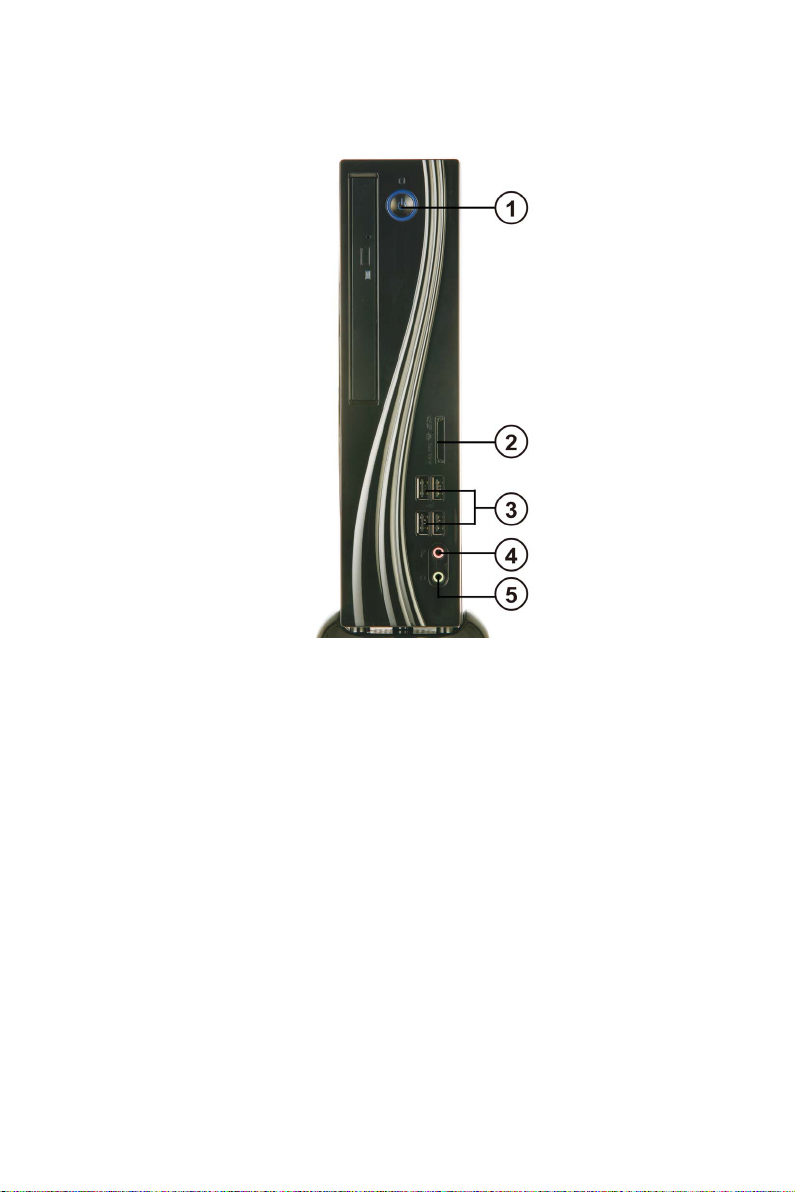
1. Power Button
2. 4 IN 1 Card
Reader
3. USB Connectors
4. Mic In Jack
5. Headphone Jack
Note:
ID design may vary.
Press the prower button to turn the system on and
off.
Supports SD Card/ MMC Card/ MS Card. You can easily read phone or other files on the momery card.
Digital cameras, DVs, MP3 or any other digital devices are compatible.
The USB connector is used for USB devices, such as
mouse, keyboard, printer, scanner and other USBcompatible device.
Connecting Microphone.
Connecting Headphone.
Introducing the PC
Page 10
4
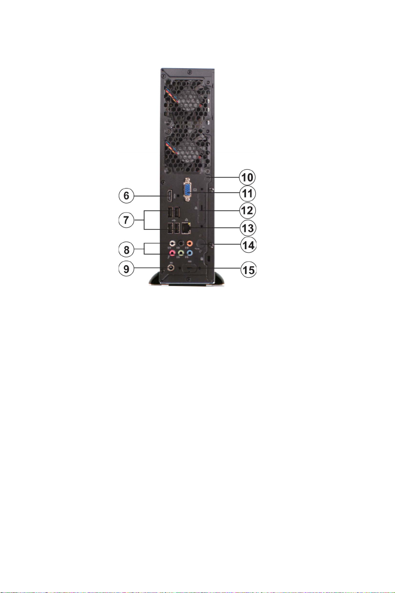
6. HDMI Connector
7. USB Connectors
8. Eight channel HD
Audio
9. DC Jack
10. Antenna It is used for an optional antenna.
11. D-SUB Connector
12. LPT Port (optional)
13. LAN
14. TV Tuner (optional)
15. COM Port (optional)
Connecting HDMI Device.
Connecting USB Devices (USB2.0 Ports).
Microphone Jack/ Headphone Jack/ Line In Jack.
It is used for power adapter.
Connecting VGA Monitor.
Connecting the printer, scanner or other devices.
Connecting the Network.
TV in jack.
Connecting a serial port extension bracket.
Introducing the PC
Page 11

Packing Contents
5
Driver DVD
Stand
NOTE:
Please contact us immediately if any of the items is damaged or missing.
Manual
Power
Introducing the PC
Page 12

6
Memo
Introducing the PC
Page 13

Chapter 2
Installing the PC
System Quick Installation
1. Connecting HDMI device.
2. Connecting VGA Monitor. (D-SUB Connector)
7
3. The USB connector is for attaching USB devices, such as mouse, keyboard, printer,
scanner and other USB-compatible device.
Installing the PC
Page 14

8
4. Connecting the Network. (LAN Connector)
5. Connecting the Microphone. (Microphone Jack)
6. Connecting Speakers or Headphones. (Headphone Jack)
7. Connecting External Audio Device. (Line In Jack)
Installing the PC
Page 15

8. Connecting Power. (DC jack)
9
Installing the PC
Page 16

10
Memo
Installing the PC
Page 17

Chapter 3
Using BIOS
About the Setup Utility
The computer uses the latest “American Megatrends Inc. ” BIOS with support for
Windows Plug and Play. The CMOS chip on the motherboard contains the ROM
setup instructions for configuring the motherboard BIOS.
The BIOS (Basic Input and Output System) Setup Utility displays the system’s
configuration status and provides you with options to set system parameters. The
parameters are stored in battery-backed-up CMOS RAM that saves this information
when the power is turned off. When the system is turned back on, the system is
configured with the values you stored in CMOS.
The BIOS Setup Utility enables you to configure:
• Hard drives, diskette drives and peripherals
• Video display type and display options
• Password protection from unauthorized use
• Power Management features
The settings made in the Setup Utility affect how the computer performs. Before
using the Setup Utility, ensure that you understand the Setup Utility options.
11
This chapter provides explanations for Setup Utility options.
The Standard Configuration
A standard configuration has already been set in the Setup Utility. However, we
recommend that you read this chapter in case you need to make any changes in the
future.
This Setup Utility should be used:
• when changing the system configuration
• when a configuration error is detected and you are prompted to make
changes to the Setup Utility
• when trying to resolve IRQ conflicts
• when making changes to the Power Management configuration
• when changing the password or making other changes to the Security
Setup
Entering the Setup Utility
When you power on the system, BIOS enters the Power-On Self Test (POST)
routines. POST is a series of built-in diagnostics performed by the BIOS. After the
POST routines are completed, the following message appears:
Press DEL to enter SETUP
Using BIOS
Page 18

12
Press the delete key to access BIOS Setup Utility.
Above image is for reference only, for details please refer to actual
image.
Resetting the Default CMOS Values
When powering on for the first time, the POST screen may show a “CMOS
Settings Wrong” message. This standard message will appear following a clear
CMOS data at factory by the manufacturer. You simply need to Load Default
Settings to reset the default CMOS values.
Note: Changes to system hardware such as different CPU, memories, etc. may also
trigger this message.
Using BIOS
When you start the Setup Utility, the main menu appears. The main menu of the
Setup Utility displays a list of the options that are available. A highlight indicates
which option is currently selected. Use the cursor arrow keys to move the highlight
to other options. When an option is highlighted, execute the option by pressing
<Enter>.
Some options lead to pop-up dialog boxes that prompt you to verify that you wish to
execute that option. Other options lead to dialog boxes that prompt you for information.
Some options (marked with an icon ) lead to submenus that enable you to change
the values for the option. Use the cursor arrow keys to scroll through the items in the
submenu.
Using BIOS
Page 19

In this manual, default values are enclosed in parenthesis. Submenu items are denoted
by an icon .
The default BIOS setting for this motherboard apply for most conditions
with optimum performance. We do not suggest users change the default
values in the BIOS setup and take no responsibility to any damage
caused by changing the BIOS settings.
BIOS Navigation Keys
The BIOS navigation keys are listed below:
KEY FUNCTION
ESC Exits the current menu
+/- Modifies the selected field’s values
Enter Select
F1 General Help
F2 Previous V
F3 Optimized Defaults
F4 Save & Exit
1. For the purpose of better product maintenance, the manufacture
reserves the right to change the BIOS items presented in this manual.
The BIOS setup screens shown in this chapter are for reference only and
may differ from the actual BIOS. Please visit the manufacture’s website
for updated manual.
2. In this Gui BIOS, you can operate by mouse or keyboard. Click : select
item; Double click: enter; Right click: exit.
Scrolls through the items on a menu
alue
13
Main Menu
This menu shows the information of BIOS and enables you to set the system
language, date and time.
Main Advanced Chipset Freq/Volt Control Boot Security Exit
BIOS Information
System Language English
System Date Mon 04/09/2012
System Time 03:39:40
Choose the system default
language
: Select Screen
/Click: Select Item
Enter/Dbl Click : Select
+/- : Change Opt.
F1: General Help
F2: Previous Values
F3: Optimized Defaults
F4: Save & Exit
ESC/Right Click: Exit
Using BIOS
Page 20

14
System Language (English)
This item is used to set system language.
System Date & Time
The Date and Time items show the current date and time on the computer. If you are
running a Windows OS, these items are automatically updated whenever you make
changes to the Windows Date and Time Properties utility.
Advanced Menu
The Advanced menu items allow you to change the settings for the CPU and other
system.
Main Advanced Chipset Freq/Volt Control Boot Security Exit
LAN Configuration
PC Health Status
Power Management Setup
ACPI Settings
CPU Configuration
SAT A Configuration
USB Configuration
Super IO Configuration
LAN Configuration Parameters
: Select Screen
/Click: Select Item
Enter/Dbl Click : Select
+/- : Change Opt.
F1: General Help
F2: Previous Values
F3: Optimized Defaults
F4: Save & Exit
ESC/Right Click: Exit
LAN Configuration
The item in the menu shows the LAN-related information that the BIOS
automatically detects.
Main Advanced Chipset Freq/Vol Control Boot Security Exit
LAN Configuration
Onboard LAN Controller Enabled
Network Boot Protocol PXE
Boot Order Int 18h
Enable/Disable Onboard
LAN 1 Controller
: Select Screen
/Click: Select Item
Enter/Dbl Click : Select
+/- : Change Opt.
F1: General Help
F2: Previous Values
F3: Optimized Defaults
F4: Save & Exit
ESC/Right Click: Exit
Using BIOS
Page 21

Onboard LAN Controller (Enabled)
Use this item to enable or disable the Onboard LAN.
Network Boot Protocol (PXE)
This item shows the information of the network boot protocol.
Boot Order (Int 18h)
This item shows the information of the boot order.
The LAN Configuration will be different depending on the settings of
Operating system select and Launch PXE OpROM in the Boot menu.
When the Operating system select item is Windows 7 or other OS and the
Launch PXE OpROM item is Enabled, the above screen will appear.
Main Advanced Chipset Freq/Vol Control Boot Security Exit
LAN Configuration
Onboard LAN Controller Enabled
Ipv4 PXE Support Enabled
Ipv6 PXE Support Enabled
Enable/Disable Onboard
LAN 1 Controller
: Select Screen
/Click: Select Item
Enter/Dbl Click : Select
+/- : Change Opt.
F1: General Help
F2: Previous Values
F3: Optimized Defaults
F4: Save & Exit
ESC/Right Click: Exit
15
Onboard LAN Controller (Enabled)
Use this item to enable or disable the Onboard LAN.
Ipv4/6 PXE Support (Enabled)
Use these items to enable Ipv4/6 PXE Boot Support. If disabled Ipv4/6 PXE, boot
option will not be created.
The LAN Configuration will be different depending on the settings of
Operating system select and Launch PXE OpROM in the Boot menu.
When the Operating system select item is Windows 8 and the Launch
PXE OpROM item is Enabled, the above screen will appear.
Press <Esc> to return to the Advanced Menu page.
Using BIOS
Page 22

16
PC Health Status
On motherboards support hardware monitoring, this item lets you monitor the
parameters for critical voltages, temperatures and fan speeds.
Main Advanced Chipset Freq/V olt Control Boot Security Exit
PC Health Status
System Temperature : 2 8 ° C
System Fan 1 Speed : 5443 RPM
System Fan 2 Speed : 0 RPM
CPU Voltage : 1.212 V
IMC Voltage : 1.056 V
DIMM Voltage : 1.512 V
-=- PECI Mode -=Offset to TCC Activation Temp. : -58
: Select Screen
/Click: Select Item
Enter/Dbl Click : Select
+/- : Change Opt.
F1: General Help
F2: Previous Values
F3: Optimized Defaults
F4: Save & Exit
ESC/Right Click: Exit
System Component Characteristics
These items display the monitoring of the overall inboard hardware health
events, such as System & CPU temperature, CPU & DIMM voltage, CPU &
system fan speed,... etc.
• System temperature
•
• CPU Voltage
System Fan 1/2 Speed
• IMC Voltage
• DIMM Voltage
Press <Esc> to return to the Advanced Menu page.
Using BIOS
Page 23

Power Management Setup
This page sets up some parameters for system power management operation.
Main Advanced Chipset Freq/V olt Control Boot Security Exit
Power Management Setup
Resume By RING Disabled
Resume By PME Disabled
Resume By USB 1.x/2.0 (S3) Disabled
EUP Function Enabled
Power LED Type Single Color LED
About Resume by Ring
: Select Screen
/Click: Select Item
Enter/Dbl Click : Select
+/- : Change Opt.
F1: General Help
F2: Previous Values
F3: Optimized Defaults
F4: Save & Exit
ESC/Right Click: Exit
Resume By RING (Disabled)
An input signal on the serial Ring Indicator (RI) line (in other words, an incoming call
on the modem) awakens the system from a soft off state.
Resume By PME (Disabled)
The system can be turned off with a software command. If you enable this item, the
system can automatically resume if there is an incoming call on the PCI Modem or
PCI LAN card.
You must use an ATX power supply in order to use this feature. Use
this item to do wake-up action if inserting the PCI card.
Resume By USB 1.x/2.0 (S3) (Disabled)
This item allows you to enable/disable the USB device wakeup function from S3
mode.
EUP Support (Enabled)
This item allows user to enable or disable EUP support.
Power LED Type (Single Color LED)
This item shows the type of the Power LED.
17
Press <Esc> to return to the Advanced Menu page.
Using BIOS
Page 24

18
ACPI Setting
The item in the menu shows the highest ACPI sleep state when the system
enters suspend.
Main Advanced Chipset Freq/V olt Control Boot Security Exit
ACPI Settings
ACPI Sleep State [S3 (Suspend to RAM)]
Select the highest ACPI
sleep state the system will
enter when the SUSPEND
button is pressed.
: Select Screen
/Click: Select Item
Enter/Dbl Click : Select
+/- : Change Opt.
F1: General Help
F2: Previous Values
F3: Optimized Defaults
F4: Save & Exit
ESC/Right Click: Exit
ACPI Sleep State (S3(Suspend to RAM))
This item allows user to enter the
ACPI S3 (Suspend toRAM) Sleep State (default).
Press <Esc> to return to the Advanced Menu page.
Using BIOS
Page 25

CPU Configuration
The item in the menu shows the information of the CPU.
Main Advanced Chipset Freq/V olt Control Boot Security Exit
CPU Configuration
Intel(R) Celeron(R) CPU G550 @ 2.60GHz
EMT64 Supported
Processor Speed 2600 MHz
Processor Stepping 206a7
Microcode Revision 25
Processor Cores 2
Intel HT Technology Not Supported
Intel VT-x T echnology Supported
Active Processor Cores All
Limit CPUID Maximum Disabled
Execute Disable Bit Enabled
Intel Virtualization T echnology Enabled
CPU C3 Report Disabled
CPU C6 Report Enabled
Enhanced Halt (C1E) Enabled
Number of cores to enable
in each processor package.
: Select Screen
/Click: Select Item
Enter/Dbl Click : Select
+/- : Change Opt.
F1: General Help
F2: Previous Values
F3: Optimized Defaults
F4: Save & Exit
ESC/Right Click: Exit
Inter(R) Celeron (R) CPU G550 @ 2.60GHz
This is display-only field and diaplays the information of the CPU installed in your
computer
.
EMT64 (Supported)
This item shows the computer supports EMT64.
Processor Speed (2600MHz)
This item shows the processor speed.
Processor Stepping (206a7)
This item shows the information of processor stepping.
Microcode Revision (25)
This item shows the Microcode revision.
Processor Cores (2)
This item shows the information of the processor cores.
Intel HT Technology (Supported)
This item shows your computer does not support Intel HT technology or not.
Intel VT-x Technology (Supported)
This item shows your computer does not support Intel VT-x technology or not.
Active Processor Cores (All)
Use this item to control the active processor cores.
Limit CPUID Maximum
(Disabled)
Use this item to enable or disable the maximum CPUID value limit. You can enable
this item to prevent the system from “rebooting” when trying to install Windows
NT 4.0.
19
Using BIOS
Page 26

20
Excute Disable Bit (Enabled)
This item allows the processor to classify areas in memory by where application code
can execute and where it cannot. When a malicious worm attempts to insert code in
the buffer, the processor disables code execution, preventing damage or worm propagation. Replacing older computers with Execute Disable Bit enabled systems can halt
worm attacks, reducing the need for virus related repair.
Intel Virtualization Technology (Enabled)
When enabled, a VMM can utilize the additional hardware capabilities provided by
Vandor Pool Technology.
CPU C3 Report (Disabled)
This item is used to enable or disable CPU C3 (ACPI C2) report to OS.
CPU C6 Report (Disabled)
This item is used to enable or disable CPU C6 (ACPI C3) report to OS.
Enhanced Halt (C1E) (Enabled)
This item enables or disables enhanced halt.
Press <Esc> to return to the Advanced Menu page.
SA T A Configuration
Use this item to show the mode of serial SATA configuration options.
Main Advanced Chipset Freq/V olt Control Boot Security Exit
SAT A Configuration
SAT A Mode IDE Mode
SATA Port1 Not Present
SATA Port2 Not Present
Determines how SAT A
controller(s) operate.
: Select Screen
/Click: Select Item
Enter/Dbl Click : Select
+/- : Change Opt.
F1: General Help
F2: Previous Values
F3: Optimized Defaults
F4: Save & Exit
ESC/Right Click: Exit
SATA Mode (IDE Mode)
Use this item to select SATA mode.
SATA Port1~2 (Not Present)
This motherboard supports two SATA channels and each channel allows one SATA
device to be installed. Use these items to configure each device on the SATA channel,
and each channel allows one SATA device to be installed. Use these items to configure
each device on the SATA channel.
Press <Esc> to return to the Advanced Menu page.
Using BIOS
Page 27

USB Configuration
Use this item to show the information of USB configuration.
Main Advanced Chipset Freq/V olt Control Boot Security Exit
USB Configuration
OnChip USB 3.0 Controller Enabled
Legacy USB Support Enabled
If the USB 3.0 controller is
external chip
: Select Screen
/Click: Select Item
Enter/Dbl Click : Select
+/- : Change Opt.
F1: General Help
F2: Previous Values
F3: Optimized Defaults
F4: Save & Exit
ESC/Right Click: Exit
OnChip USB 3.0 Controller (Enabled)
Use this item to enable or disable onchip USB 3.0 controller. We recommand users to
keep the default value. Disabling it might cause the USB devices not to work properly.
Legacy USB Support (Enabled)
Use this item to enable or disable support for legacy USB devices.
21
Press <Esc> to return to the Advanced Menu page.
Using BIOS
Page 28

22
Super IO Configuration
Use this item to show the information of Super IO configuration.
Main Advanced Chipset Freq/V olt Control Boot Security Exit
Super IO Configuration
Super IO Chip IT8728
Serial Port 0 Configutation
Parallel Port Configuration
Set Parameters of Serial
Port 0 (COMA)
: Select Screen
/Click: Select Item
Enter/Dbl Click : Select
+/- : Change Opt.
F1: General Help
F2: Previous Values
F3: Optimized Defaults
F4: Save & Exit
ESC/Right Click: Exit
Super IO Chipset (IT8728)
This item shows the information of the super IO chipset.
Serial Port 0 Configuration
Scroll to this item and press <Enter> to view the following screen:
Main Advanced Chipset Freq/V olt Control Boot Security Exit
Serial Port 0 Configuration
Serial Port Enabled
Device Settings IO=3F8h; IRQ=4;
Change Settings Auto
Enable or Disable Serial
Port (COM)
: Select Screen
/Click: Select Item
Enter/Dbl Click : Select
+/- : Change Opt.
F1: General Help
F2: Previous Values
F3: Optimized Defaults
F4: Save & Exit
ESC/Right Click: Exit
Serial Port (Enabled)
This item allows you to enable or disable serial port.
Device Settings (IO=3F8h; IRQ=4)
This item shows the information of the device settings.
Change Settings (Auto)
Use this item to change device settings.
Press <Esc> to return to the Super IO Configuration page.
Using BIOS
Page 29

Parallel Port Configuration
Scroll to this item and press <Enter> to view the following screen:
Main Advanced Chipset Freq/V olt Control Boot Security Exit
Parallel Port Configuration
Parallel Port Enabled
Device Se tti ngs IO=378h; IRQ=5; DMA=3
Change Settings Auto
Device Mode ECP Mode
Enabled or Disabled
Parallel Port (LPT/LPTE)
: Select Screen
/Click: Select Item
Enter/Dbl Click : Select
+/- : Change Opt.
F1: General Help
F2: Previous Values
F3: Optimized Defaults
F4: Save & Exit
ESC/Right Click: Exit
Parallel Port (Enabled)
This item allows you to enable or disable parallel port.
Device Settings (IO=378h; IRQ=5; DMA=3)
This item shows the information of the device settings.
Change Settings (Auto)
Use this item to change device settings.
Device Mode (ECP Mode)
This item shows the information of the device mode.
23
Press <Esc> to return to the Super IO Configuration page.
Press <Esc> to return to the Advanced Menu page.
Using BIOS
Page 30

24
Chipset Menu
The chipset menu items allow you to change the settings for the North Bridge
chipset, South Bridge chipset and other system.
Main Advanced Chipset Freq/Volt Control Boot Security Exit
System Agent Configuration
PCH Configuration
ME Configuration
System Agent Configuration
Scroll to this item and press <Enter> and view the following screen:
Main Advanced Chipset Freq/Volt Control Boot Security Exit
System Agent Configuration
IGD Memory 64M
DVMT Memory 256M
System Agent (SA)
Parameters
: Select Screen
/Click: Select Item
Enter/Dbl Click : Select
+/- : Change Opt.
F1: General Help
F2: Previous Values
F3: Optimized Defaults
F4: Save & Exit
ESC/Right Click: Exit
Select DVMT 5.0 PreAllocated (Fixed)
Graphics Memory size
used by the Internal
Graphics Device.
: Select Screen
/Click: Select Item
Enter/Dbl Click : Select
+/- : Change Opt.
F1: General Help
F2: Previous Values
F3: Optimized Defaults
F4: Save & Exit
ESC/Right Click: Exit
IGD Memory (64M)
This item shows the information of the IGD(Internal Graphics device) memory.
DVMT Memory (256MB)
This item is used to select the DVMT5.0 Total Graphics Memory size by the internal
Graphics Device.
Press <Esc> to return to the Chipset Menu page.
Using BIOS
Page 31

PCH Configuration
Scroll to this item and press <Enter> to view the following screen.
Main Advanced Chipset Freq/Volt Control Boot Security Exit
PCH Configuration
Restore AC Power Loss Power Off
Audio Configuration
Azalia HD Audio Enabled
Azalia Internal HDMI codec Enabled
Specify what state to go to
when power is re-applied
after a power failure.
: Select Screen
/Click: Select Item
Enter/Dbl Click : Select
+/- : Change Opt.
F1: General Help
F2: Previous Values
F3: Optimized Defaults
F4: Save & Exit
ESC/Right Click: Exit
Restore AC Power Loss (Power Off)
This item specifies what state to go to when power is
re-applied after a power failure
(G3 state).
Audio Configuration
This item shows the information of the audio configuration.
Azalia HD Audio (Enabled)
This item enables or disables Azalia HD audio.
Azalia Internal HDMI codec (Enabled)
This item enables or disables Azalia Internal HDMI codec.
25
Press <Esc> to return to the Chipset Menu page.
Using BIOS
Page 32

26
ME Configuration
Scroll to this item and press <Enter> to view the following screen.
Main Advanced Chipset Freq/Volt Control Boot Security Exit
Management Engine T echnology Configuration
ME FW Version 8. 1. 0. 1248
: Select Screen
/Click: Select Item
Enter/Dbl Click : Select
+/- : Change Opt.
F1: General Help
F2: Previous Values
F3: Optimized Defaults
F4: Save & Exit
ESC/Right Click: Exit
ME FW Version (8.1.0.1248)
This item shows the ME FW version.
Press <Esc> to return to the Chipset Menu page.
Using BIOS
Page 33

Freq/Volt Control Menu
This page enables you to set the clock speed and system bus for your system. The
clock speed and system bus are determined by the kind of processor you have
installed in your system.
Main Advanced Chipset Freq/Volt Control Boot Security Exit
Frequency/Voltage Control
CPU Advanced Configuration
Chipset Advanced Configuration
CPU Advanced
Configuration
27
Auto Detect DIMM/PCI Clk Enabled
Spread Spectrum Enabled
Genuine Intel(R) CPU @ 2.20GHz
Processor Speed 2200 MHz
Memory Frequency 1333 MHz
T otal Memory 2048 MB (DDR3)
: Select Screen
/Click: Select Item
Enter/Dbl Click : Select
+/- : Change Opt.
F1: General Help
F2: Previous Values
F3: Optimized Defaults
F4: Save & Exit
ESC/Right Click: Exit
CPU Advanced Configuration
Scroll to this item and press <Enter> to view the following screen.
Main Advanced Chipset Freq/Volt Control Boot Security Exit
CPU OverClocking Configuration
CPU Frequency(1/100 MHz) 10000
CPU Ratio 22
Enhanced Intel SpeedStep T echnology Enabled
Turbo Mode Enabled
Runtime Turbo Enable Disabled
Intel Graphics Configuration
Graphics Core Ratio Limit 18
Graphics Voltage (1/256) 0
Enhanced Intel SpeedStep
Technology
: Select Screen
/Click: Select Item
Enter/Dbl Click : Select
+/- : Change Opt.
F1: General Help
F2: Previous Values
F3: Optimized Defaults
F4: Save & Exit
ESC/Right Click: Exit
CPU Frequency (1/100 MHz) (10000)
This item shows the information of the CPU frequency.
CPU Ratio (22)
This item allows users to control non turbo CPU ratio.
Enhanced Intel SpeedStep Technology (Enabled)
This item allows users to enable or disable the EIST (Enhanced Intel SpeedStep
Technology).
Turbo Mode (Enabled)
This item allows you to control the Intel Turbo Boost Technology.
Using BIOS
Page 34

28
Runtime Turbo Enable (Disabled)
This item shows if CPU support runtime turbo or not.
Graphics Core Ratio Limit (18)
This item allows you to control the internal GFX Turbo ratio.
Graphics Voltage(1/256) (0)
This item allows you to adjust the internal GFX voltage.
Press <Esc> to return to the Freq/Volt Control page.
Using BIOS
Page 35

Chipset Advanced Configuration
Scroll to this item and press <Enter> to view the following screen:
Main Advanced Chipset Freq/Volt Control Boot Security Exit
Memory Multiplier Configuration
CAS# Latency (tCL) 9
RAS# to CAS# Delay(tRCD) 9
Row Precharge Time (tRP) 9
RAS# Active Time (tRAS) 24
Write Recovery Time(tWR) 10
Row Refresh Cycle Time(tRFC) 7 4
Active to Active Delay(tRRD) 4
Write to Read Delay(tWTR) 5
Read CAS# Precharge(tRTP) 5
Four Active Window Delay(tFAW) 20
: Select Screen
/Click: Select Item
Enter/Dbl Click : Select
+/- : Change Opt.
F1: General Help
F2: Previous Values
F3: Optimized Defaults
F4: Save & Exit
ESC/Right Click: Exit
Memory Timing Configuration
This item shows the information of Memory Timing Configuration.
CAS# Latency(tCL) (9)
This item determines the operation of DDR SDRAM memory CAS (column address
strobe). It is recommanded that you leave this item at the default value. The 2T
setting requires faster memory that specifically supports this mode.
RAS# to CAS# Delay(tRD) (9)
This item specifies the RAS# to CAS# delay to Rd/Wr command to the same bank.
Row Precharge Time(tRP) (9)
This item specifies Row precharge to Active or Auto-Refresh of the same bank.
RAS# Active Time(tRAS) (24)
This item specifies the RAS# active time.
Write Recovery Time(tWR) (10)
This item specifies the write recovery time.
Row Refresh Cycle Time(tRFC) (74)
This item specifies the row refresh cycle time.
Active to Active Delay(tRRD) (4)
This item controls the active bank x to active bank y in memory clock cycles.
Write to Read Delay(tWTR) (5)
This item specifies the write to read delay time.
Read CAS# Precharge(tRTP) (5)
This item controls the Read to precharge delay for memory devices, in memory
clock cycles.
Four Active Window Delay(tFAW) (20)
This item controls the four bank activate time in memory clock cycles.
Press <Esc> to return to the Freq/Volt Control page.
Using BIOS
29
Page 36

30
Auto Detect DIMM/PCI Clk (Enabled)
When this item is enabled, BIOS will disable the clock signal of free DIMM/PCI slots.
Spread Spectrum (Enabled)
If you enable spread spectrum, it can significantly reduce the EMI (Electro-Magnetic
Interference) generated by the system.
Genuine Intel(R) CPU @ 2.20GHz
This is display-only field and displays the information of the CPU installed in your
computer.
Processor Speed (2200MHz)
This item shows the CPU speed.
Memroy Frequency (1333 MHz)
This item shows the memroy frequency.
Total Memory (2048MB(DDR3))
This item shows the total momery of DDR3.
Using BIOS
Page 37

Boot Menu
This page enables you to set the keyboard NumLock state.
Main Advanced Chipset Freq/Volt Control Boot Security Exit
Boot Configuration
Operation System Select Windows7 or other OS
Launch PXE OpROM Disabled
Launch Storage OpROM Enabled
Bootup NumLock State On
Quiet Boot Enabled
Boot mode select LEGACY
Set Boot Priority
Boot Option #1 Hard Disk
Boot Option #2 CD/DVD
Boot Option #3 USB Floppy
Boot Option #4 USB CD/DVD
Boot Option #5 USB Hard Disk
Boot Option #6 USB Key: Ut165 1.00
Boot Option #7 Network
Hard Disk Drive Priorities [Press Enter]
CD/DVD ROM Drive Priorities [Press Enter]
USB/ Floppy Drive Priorities [Press Enter]
USB CD/DVD ROM Drive Priorities [Press Enter]
USB HardDisk Drive Priorities [Press Enter]
USB Flash Drive Priorities [Press Enter]
Network Device Priorities [Press Enter]
CSM parameters [Press Enter]
Windows 7 or other OS:
Boot policy for Legacy OS
Windows 8: Boot Policy for
UEFI OS without
Compatibility Support
Module (CSM)
Manual: User customized
CSM parameters & boot
policy
: Select Screen
/Click: Select Item
Enter/Dbl Click : Select
+/- : Change Opt.
F1: General Help
F2: Previous Values
F3: Optimized Defaults
F4: Save & Exit
ESC/Right Click: Exit
31
Boot Configuration
This item shows the information of the Boot Configuration.
Operation System Select (Windows7 or other OS)
This item is used to select the operation system.
Launch PXE OpROM (Disabled)
The item enables or disables launch PXE Option ROM.
Launch Storage OpROM (Enabled)
The item enables or disables launch Storage Option ROM.
Bootup NumLock State (On)
This item enables you to select NumLock state.
Quiet Boot (Enabled)
This item enables or disables quiet boot.
Boot mode select (LEGACY)
Use this item to select boot mode.
Set Boot Priority
This item enables you to set boot priority for all boot devices.
Boot Option #1/2/3/4/5/6/7
These items show the boot priorities.
Using BIOS
Page 38

32
Hard Disk / CD/DVD ROM / USB Floppy / USB CD/DVD ROM / USB HardDisk /
USB Flash / Network Boot Drive Priorities
These items enable you to specify the sequence of loading the operating system.
Press <Enter> to see the submenu.
CSM parameters
OpROM execution, boot options filter,etc.
CSM parameters
Scroll to this item and press <Enter> to view the following screen.
Main Advanced Chipset Freq/Volt Control Boot Security Exit
Launch CSM Always
Boot option filter UEFI and Legacy
Launch PXE OpROM policy Do not launch
Launch Storage OpROM policy Legacy only
Launch Video OpROM policy Legacy only
Other PCI device ROM priority Legacy OpROM
This option controls if CSM
will be launched
: Select Screen
/Click: Select Item
Enter/Dbl Click : Select
+/- : Change Opt.
F1: General Help
F2: Previous Values
F3: Optimized Defaults
F4: Save & Exit
ESC/Right Click: Exit
Launch CSM (Always)
This option controls if CSM will be launched.
Boot option filter (UEFI and Legacy)
This option controls what devices system can boot to.
Launch PXE OpROM policy (Do not Launch)
This controls the execution of UEFI and Legacy PXE OpROM.
Launch Storage OpROM policy (Legacy only)
This controls the execution of UEFI and Legacy Storage OpROM.
Launch Video OpROM policy (Legacy only)
This controls the execution of UEFI and Legacy Video OpROM.
Other PCI device ROM priority (Legacy OpROM)
For PCI devices other than Network, Mass storage or Video defines which OpROM to
launch.
Using BIOS
Page 39

Security Menu
This page enables you to set setup administrator password and user password.
Main Advanced Chipset Freq/Volt Control Boot Security Exit
Administrator Password Status Not Install
User Password Status Not Install
Administrator Password
System Mode state Setup
Secure Boot state Disabled
Secure Boot Enabled
Secure Boot Mode Custom
Image Execution Policy
Key Management
Administrator Password Status (Not Installed)
This item shows adiministrator password installed or not.
User Password Status (Not Installed)
This item shows user password installed or not.
System Mode state (Setup)
This item shows system mode setup or not.
Secure Boot state (Disabled)
This item allows you to enable or disable the secure boot state.
Secure Boot (Enabled)
This item is used to control the secure boot flow, it is possible only if system runs in
User Mode.
Secure Boot Mode (Custom)
This item is used to select secure boot mode, when you select standard mode, secure
boot policy is fixed; when you select custom mode, the image execution policy and
secure boot key databases are changeable.
Secure Boot mode selector.
‘Standard’ -fixed Secure
boot policy, ‘Custom’ changeable Image
Execution policy and Secure
Boot Key databases
: Select Screen
/Click: Select Item
Enter/Dbl Click : Select
+/- : Change Opt.
F1: General Help
F2: Previous Values
F3: Optimized Defaults
F4: Save & Exit
ESC/Right Click: Exit
33
Using BIOS
Page 40

34
Image Execution Policy
Scroll to this item to view the following screen:
Main Advanced Chipset Freq/Volt Control Boot Security Exit
Internal FV Always Execute
Option ROM Deny Execute
Removable Media Deny Execute
Fixed Media Deny Execute
Image Execution Policy per
device path on Security
Violation. Note: Only users
logged with Administrative
password can exercise
Query User policy setting
: Select Screen
/Click: Select Item
Enter/Dbl Click : Select
+/- : Change Opt.
F1: General Help
F2: Previous Values
F3: Optimized Defaults
F4: Save & Exit
ESC/Right Click: Exit
Internal FV/Option ROM/Removable Media/Fixed Media (Always Execute/
Deny Execute)
These items allow you to select image execution policy per device path on security
violation. Only users logged with administrative password can exercise query user
policy setting.
Press <Esc> to return to the Security Menu page.
Using BIOS
Page 41

Key Management
Scroll to this item to view the following screen:
Main Advanced Chipset Freq/Volt Control Boot Security Exit
Default Key Provisioning Disabled
Manage All Factory Keys (PK, KEK, DB, DBX)
Install default Secure Boot keys
Platform Key (PK) NOT INSTALLED
Set PK from File
Get PK to File
Delete the PK
Key Exchange Key Database (KEK) NOT INSTALLED
Set KEK from File
Get KEK to File
Delete the KEK
Append an entry to KEK
Authorized Signature Database (DB) NOT INSTALLED
Set DB from File
Get DB to File
Delete the DB
Append an entry to DB
Forbidden Signature Database (DBX) NOT INSTALLED
Set DBX from File
Get DBX to File
Delete the DBX
Append an entry to DBX
Force OEM default Secure
Boot Keys if System is in
Setup Mode.
: Select Screen
/Click: Select Item
Enter/Dbl Click : Select
+/- : Change Opt.
F1: General Help
F2: Previous Values
F3: Optimized Defaults
F4: Save & Exit
ESC/Right Click: Exit
Default Key Provisioning (Disabled)
This item enables or disables you to force OEM default secure boot keys if system is
in setup mode.
Platform Key (PK)
This item shows the information of the platform key.
Set PK/KEK/DB/DBX from File
This item launches the file browser to set Efi Variable from the file. The file data
must be formatted as Efi Variable with TimeBased Authenticated Header.
Get PK/KEK/DB/DBX to File
This item is used to store secure variable to a file with a matching name in selected
file system’s root.
Delete the PK/KEK/DB/DBX
This item is used to delete the variable.
Key Exchange Key Database (KEK)
This item shows the information of the key exchange key database.
Authorized Signature Database (DB)
This item shows the information of the authorized signature database.
Forbidden Signature Database (DBX)
This item shows the information of the forbidden signature database.
Append an entry to KEK/DB/DBX
This item launches the file browser to Append new signature database from the file.
The file data must be formatted as Efi Variable with TimeBased Authenticated Header.
35
Using BIOS
Page 42

36
Exit Menu
This page enables you to exit system setup after saving or without saving the
changes.
Main Advanced Chipset Freq/Volt Control Boot Security Exit
Back to EZ Mode
Save Changes and Exit
Discard Changes and Exit
Save Changes and Reset
Discard Changes and Reset
Save Options
Save Changes
Discard Changes
Restore Defaults
Save as User Defaults
Restore User Defaults
Boot Override
Back to EZ Mode
This item enables you to back to EZ mode.
Save Changes and Exit
This item enables you to save the changes that you have made and exit.
Discard Changes and Exit
This item enables you to discard any changes that you have made and exit.
Save Changes and Reset
This item enables you to save the changes that you have made and reset.
Discard Changes and Reset
This item enables you to discard any changes that you have made and reset.
Save Options
This item enables you to save the options that you have made.
Save Changes
This item enables you to save the changes that you have made.
Discard Changes
This item enables you to discard any changes that you have made.
Restore Defaults
This item enables you to restore the system defaults.
Save as User Defaults
This item enables you to save the changes that you have made as user defaults.
Restore User Defaults
This item enables you to restore user defaults.
Boot Override
Use this item to select the boot device.
Go back to EZ Mode.
: Select Screen
/Click: Select Item
Enter/Dbl Click : Select
+/- : Change Opt.
F1: General Help
F2: Previous Values
F3: Optimized Defaults
F4: Save & Exit
ESC/Right Click: Exit
Using BIOS
Page 43

Updating the BIOS
You can download and install updated BIOS for this motherboard from the
manufacturer’s Web site. New BIOS provides support for new peripherals, improvements in performance, or fixes for known bugs. Install new BIOS as follows:
1 If your motherboard has a BIOS protection jumper, change the setting to
allow BIOS flashing.
2 If your motherboard has an item called Firmware Write Protect in Ad-
vanced BIOS features, disable it. (Firmware Write Protect prevents
BIOS from being overwritten.)
3 Prepare a bootable device or create a bootable system disk. (Refer to
Windows online help for information on creating a bootable system
disk.)
4 Download the Flash Utility and new BIOS file from the manufacturer’s
Web site. Copy these files to the bootable device.
5 Turn off your computer and insert the bootable device in your com-
puter. (You might need to run the Setup Utility and change the boot
priority items on the Advanced BIOS Features Setup page, to force
your computer to boot from the bootable device first.)
6 At the C:\ or A:\ prompt, type the Flash Utility program name and the file
name of the new BIOS and then press <Enter>. Example: AFUDOS.EXE
040706.ROM
7 When the installation is complete, remove the bootable device from the
computer and restart your computer. If your motherboard has a Flash
BIOS jumper, reset the jumper to protect the newly installed BIOS from
being overwritten. The computer will restart automatically.
37
This concludes Chapter 3. Refer to the next chapter for information on the software
supplied with the motherboard.
Using BIOS
Page 44

38
Memo
Using BIOS
Page 45

Chapter 4
Using the Software
About the Software DVD-ROM/CD-ROM
The support software DVD-ROM/CD-ROM that is included in the motherboard
package contains all the drivers and utility programs needed to properly run the
bundled products. Below you can find a brief description of each software program,
and the location for your motherboard version. More information on some programs is available in a README file, located in the same directory as the software.
Before installing any software, always inspect the folder for files named README.TXT
or something similar. These files may contain important information that is not
included in this manual.
Never try to install all software from folder that is not specified for use with
1.
your motherboard.
The notice of Intel HD audio installation (optional): The Intel High Defi-
2.
nition audio functionality unexpectedly quits working in Windows Server
2003 Service Pack 1 or Windows XP Professional x64 Edition. Users need
to download and install the update packages from the Microsoft Download
Center “before” installing HD audio driver bundled in the Driver disk.
Please log on to
us;901105#appliesto for more information.
http://support.microsoft.com/default.aspx?scid=kb;en-
Auto-installing under Windows 7/8
The Auto-install DVD-ROM/CD-ROM makes it easy for you to install the drivers
and software for your motherboard.
If the Auto-install DVD-ROM/CD-ROM does not work on your system,
you can still install drivers through the file manager for your OS (for
example, Windows Explorer). Refer to the Utility Folder Installation Notes
later in this chapter.
The support software DVD-ROM/CD-ROM disk loads automatically under Windows
7/8. When you insert the DVD-ROM/CD-ROM disk in the DVD-ROM/CD-ROM
drive, the autorun feature will automatically bring up the install screen. The screen
has three buttons on it, Setup, Browse CD and Exit.
39
If the opening screen does not appear; double-click the file “setup.exe”
in the root directory.
Using the Software
Page 46
40
Drivers Tab
Setup
Browse CD
Exit
Utilities Tab
Lists the software utilities that are available on the disk.
Information Tab
Displays the path for all software and drivers available on the disk.
Click the Setup button to run the software installation program.
Select from the menu which software you want to install.
The Browse CD button is the standard Windows command that allows you to open Windows Explorer and show the contents of the
support disk.
Before installing the software from Windows Explorer, look for a file
named README.TXT
important information to help you install the software correctly.
Some software is installed in separate folders for different operating
systems, such as Windows 7/8. Always go to the correct folder for the
kind of OS you are using.
In install the software, execute a file named SETUP.EXE by doubleclicking the file and then following the instructions on the screen.
The Exit button closes the Auto Setup window.
or something similar. This file may contain
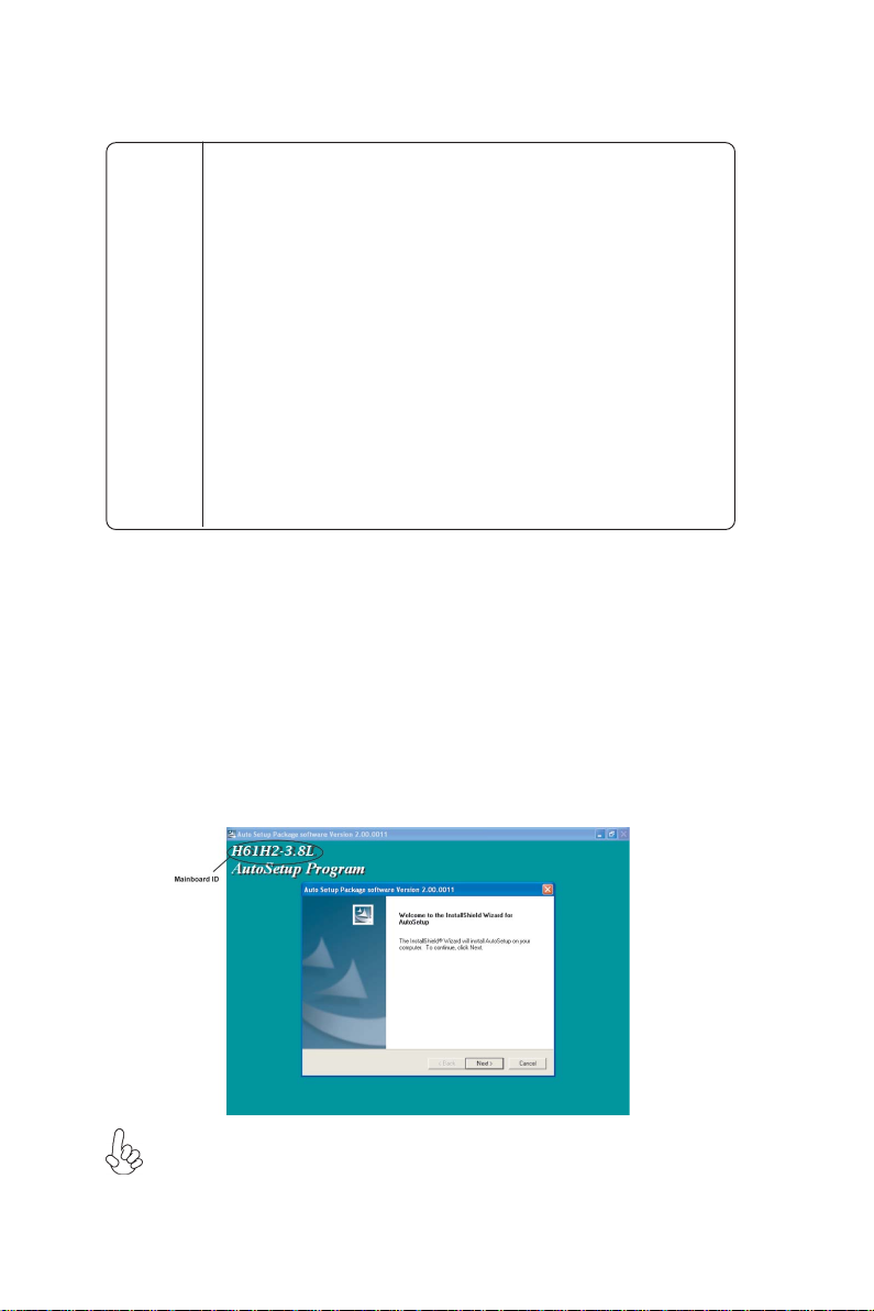
Running Setup
Follow these instructions to install device drivers and software for the motherboard:
1. Click Setup. The installation program begins:
The following screens are examples only. The screens and driver lists will be
different according to the motherboard you are installing.
The motherboard identification is located in the upper left-hand corner.
Using the Software
Page 47
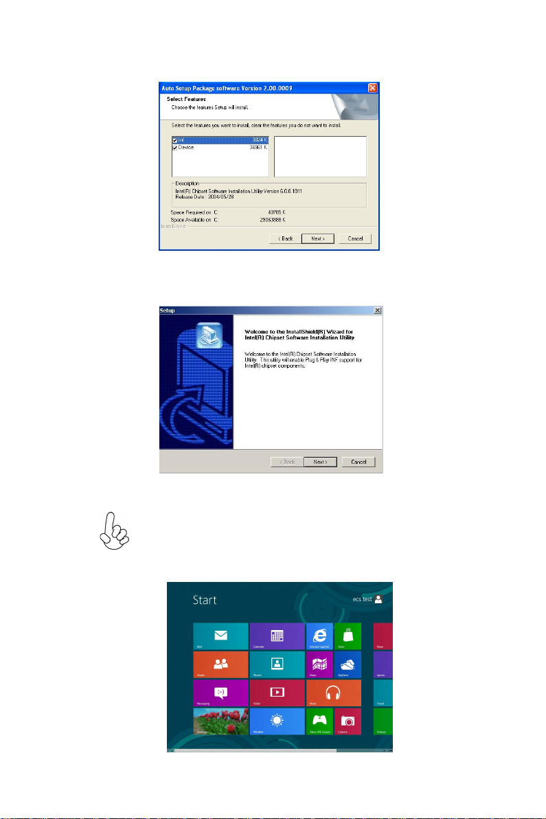
2. Click Next. The following screen appears:
3. Check the box next to the items you want to install. The default options are recom-
mended.
4. Click Next run the Installation Wizard. An item installation screen appears:
41
5. Follow the instructions on the screen to install the items.
Drivers and software are automatically installed in sequence. Follow the
onscreen instructions, confirm commands and allow the computer to
restart a few times to complete the installation.
Windows 8 will show the following screen after system restart, you must
select “Desktop” in the bottom left to install the next driver.
Using the Software
Page 48

42
Windows 7/8 will appear below UAC (User Account Control) message after
the system restart. You must select “Allow” to install the next driver.
Continue this process to complete the drivers installation.
Manual Installation
Insert the disk in the DVD-ROM/CD-ROM drive and locate the PATH.DOC file in
the root directory. This file contains the information needed to locate the drivers for
your motherboard.
Look for the chipset and motherboard model; then browse to the directory and path
to begin installing the drivers. Most drivers have a setup program (SETUP.EXE) that
automatically detects your operating system before installation. Other drivers have
the setup program located in the operating system subfolder.
If the driver you want to install does not have a setup program, browse to the
operating system subfolder and locate the readme text file (README.TXT or
README.DOC) for information on installing the driver or software for your operating system.
Utility Software Reference
All the utility software available from this page is Windows compliant. They are
provided only for the convenience of the customer. The following software is furnished under license and may only be used or copied in accordance with the terms of
the license.
These software(s) are subject to change at anytime without prior notice.
Please refer to the support disk for available software.
Using the Software
Page 49

Chapter 5
Trouble Shooting
Start up problems during assembly
After assembling the PC for the first time you may experience some start up
problems. Before calling for technical support or returning for warranty, this chapter
may help to address some of the common questions using some basic troubleshooting
tips.
a) System does not power up and the fans are not running.
1.Disassemble the PC to remove the VGA adaptor card, DDR memory, LAN, USB
and other peripherals including keyboard and mouse. Leave only the motherboard,
CPU with CPU cooler and power supply connected. Turn on again to see if the
CPU and power supply fans are running.
2. Make sure to remove any unused screws or other metal objects such as screwdrivers
from the inside PC case. This is to prevent damage from short circuit.
3. Check the CPU FAN connector is connected to the motherboard.
4. For Intel platforms check the pins on the CPU socket for damage or bent. A bent
pin may cause failure to boot and sometimes permanent damage from short circuit.
43
5. Check the 19V power connector is connected to the motherboard.
6. Check that the 19V power is fully inserted into the motherboard connectors.
Make sure the latches of the cable and connector are locked into place.
b) Power is on, fans are running but there is no display
1. Make sure the monitor is turned on and the monitor cable is properly connected
to the PC.
2. Check the VGA adapter card (if applicable) is inserted properly.
3. Listen for beep sounds. If you are using internal PC speaker make sure it is
connected.
a. continuous 3 short beeps : memory not detected
b. 1 long beep and 8 short beeps : VGA not detected
Trouble Shooting
Page 50

44
c) The PC suddenly shuts down while booting up.
1. The CPU may experience overheating so it will shutdown to protect itself.
Ensure the CPU fan is working properly.
2. From the BIOS setting, try to disable the Smartfan function to let the fan run at
default speed. Doing a Load Optimised Default will also disable the Smartfan.
Start up problems after prolong use
After a prolong period of use your PC may experience start up problems again.
This may be caused by breakdown of devices connected to the motherboard such as
HDD, CPU fan, etc. The following tips may help to revive the PC or identify the
cause of failure.
1. Clear the CMOS values using the CLR_CMOS jumper. Refer to CLR_CMOS
jumper in Chapter 2 for Checking Jumper Settings in this user manual. When
completed, follow up with a Load Optimised Default in the BIOS setup.
2. Check the system fan for dust. Long term accumulation of dust will reduce its
effectiveness to cool the processor. Clean the cooler or replace a new one if
necessary.
3. Remove the hard drive, optical drive or DDR memory to determine which of
these component may be at fault.
Maintenance and care tips
Your computer, like any electrical appliance, requires proper care and maintenance.
Here are some basic PC care tips to help prolong the life of the motherboard and
keep it running as best as it can.
1. Keep your computer in a well ventilated area. Leave some space between
the PC and the wall for sufficient airflow.
2. Keep your computer in a cool dry place. Avoid dusty areas, direct sunlight
and areas of high moisture content.
3. Routinely clean the CPU cooler fan to remove dust and hair.
4. In places of hot and humid weather you should turn on your computer once
every other week to circulate the air and prevent damage from humidity.
5. Add more memory to your computer if possible. This not only speeds up the
system but also reduces the loading of your hard drive to prolong its life span.
6. If possible, ensure the power cord has an earth ground pin directly from the
wall outlet. This will reduce voltage fluctuation that may damage sensitive devices.
Trouble Shooting
Page 51

45
tekcos llaw ot tcennoc ro
hctiws USP no nruT
.tratser dna
No
M SOC RLC tratser dna
?no denrut si hctiws USP dna
deulp si droc rewop CA gg
Basic Troubleshooting Flowchart
AMR tcatnoc >- melborp draob fI
?draob ro USP htiw melborP
seY
melborp draoB
AMR tcatnoc >-
.gn
es SOIB yfidom re
ts ot liaf metsyS elbatsnu ro tra
No
a
kcehc dna SOMC RLC
rewop V21 UPC fi
detcennoc si
CP eht tratseR
No
ylreporp ton yromem MMID
dnuos peeB ynA
seY
:speeb trohs 3 fI -
rotinom fi kcehC
yalpsid sah
seY
:speeb trohs 8 dna peeb gnol 1 fI -
eruliaf yromem ro detresni
detceted ton AGV
eussi ecived larehpireP
,rorre putes SOMC-
.melborp DDH-
No
desserp si no
.trats ot sliaf CP tub
uB rewoP
ylppuS rewoP fi kcehC
gnikrow si )USP(
tinU
No
h rotinom fi kcehC sa
seY
yalp
sid
No
neercs TSOP ta tlaH
seY
AMR tcatnoc ,liaf fI
seY
OMC RL dna SC tser .tra
d .SOMCRLC ot een
Page 52

46
Memo
Trouble Shooting
 Loading...