

Page 1

¦
chapter 1 getting to know the basics
1-1
CHAPTER? ONE
GETTING TO KNOW THE BASICS
This chapter introduces the features and
components of the computer.
Page 2

¦
chapter 1 getting to know the basics
1-2
Performance Features
?? High Performance Processor
The LCD PC is equipped with a powerful Intel Pentium 4
processor on the latest sub-micron process. The processor
also supports up to 533MHz front side bus bandwidth for
unparalleled performance.
?? Advanced Graphic Engine
The system is built with a high performance ATI Mobility
Radeon 9000 or alternatively with nVIDIA GeForce FX 5400
(NV31) video processor with a dedicated frame buffer (up to
128MB.) The advanced graphic engine is DirectX 8.1
compatible and delivers the fastest-performing 3D graphics
supporting the latest games, cinematic-quality video, and
features that dramatically enhance all aspects of the visual
experience in every application.
?? Expandability
The system offers upgradeable 3.5” hard disk drive and 2 DDR
SDRAM sockets for expansion, allowing the user to easily
increase the storage and system capacities as the need arises.
?? Large LCD Display
The computer is equipped with a large 17-inch TFT
high-resolution display panel for clear text and brilliant colors.
?? Audio Capability
The system is equipped with a build-in subwoofer and stereo
speakers, which give you more realism in sound. The system
Page 3

¦
chapter 1 getting to know the basics
1-3
also supports 6-channel 5.1 speaker output for home theater
sound system. The audio playback function supports 3D audio,
64-voices and DirectSound.
A built-in MP3 player allows you to playback MP3 tracks without
having to boot up to Windows.
The system is also equipped with a unique S/PDIF digital audio
output for external AC3, DTS, or PCM decoding processor in
your home audio-video system.
?? Communication Features
The system provides built-in Ethernet network adapter for local
network and 56K modem for point-to-point connection or
dial-up remote network.
?? Firewire (IEEE1394) and USB2.0 ports
In addition to a full array of built-in I/O ports, the computer offers
IEEE1394 for ultra high-speed connection to high bandwidth
digital video devices and 4 or 5 high-bandwidth USB2.0 ports to
connect to any USB-based peripheral devices.
?? TV Tuner (Optional)
The optional TV Tuner module allows user to watch TV or cable
programs, record TV, and capture analog video signals to the
hard drive or to the recordable optical drive (optional device).
?? Wireless LAN (Optional)
The optional internal Wireless LAN module allows your
computer to connect wirelessly to other systems, devices, or
network.
Page 4
¦
chapter 1 getting to know the basics
1-4
System At A Glance
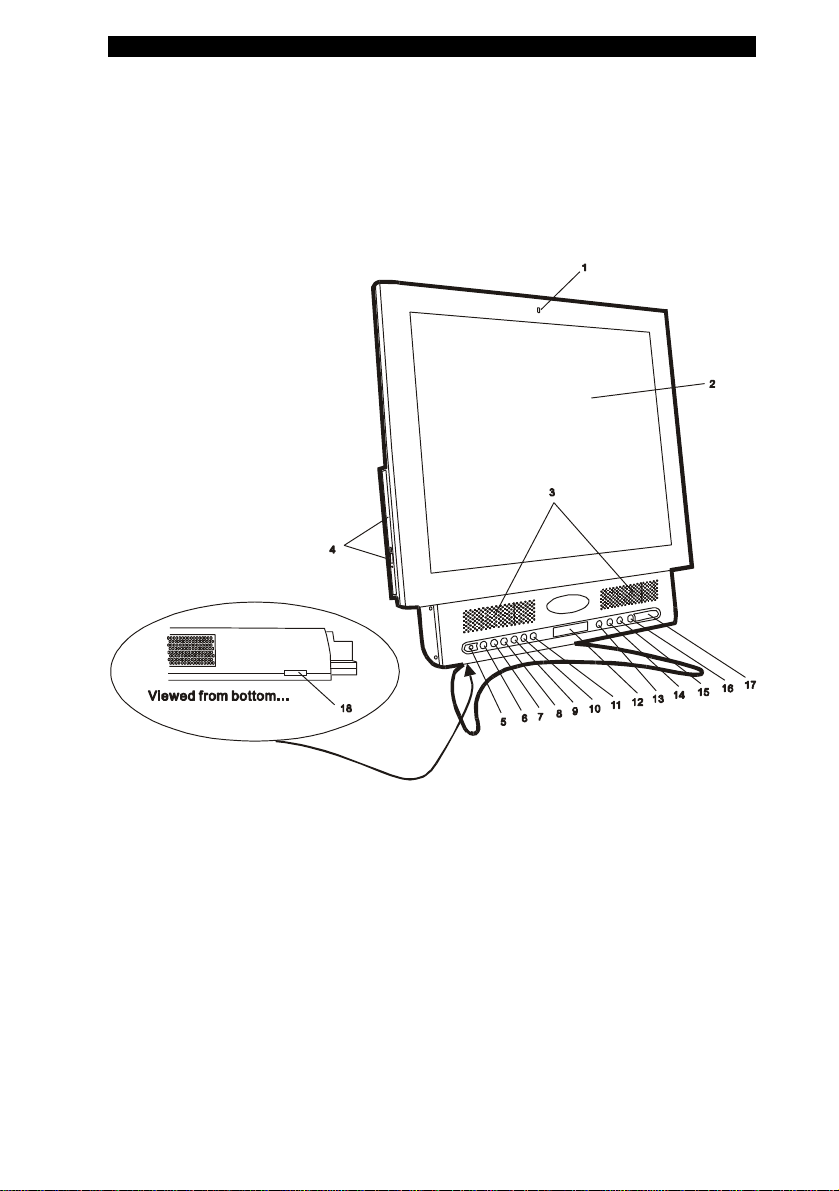
Front View
1. Microphone
The built-in microphone records sound.
2. LCD Display
The panel is where the system content is displayed.
3. Stereo Speakers With Built-in Sub-woofer
Page 5

¦
chapter 1 getting to know the basics
1-5
The built-in speakers output the sound in stereo. The sub-woofer
enhances the system’s audio lower-end frequencies.
4. DVD-ROM or Combo (DVD-ROM / CD-RW) optical drive and
Disk Eject Button and Manual Eject Key Hole
If your computer comes with DVD-ROM, you may play DVD
movies or regular CD-ROM disk. If it comes with a Combo drive,
you may save data onto a CD-R / CD-RW disk. Press the eject
button to eject the disk tray. The manual eject keyhole allows you
to manually eject a jammed disk.
5. Consumer Infrared Receiver
The lens receives input from the remote control. See later sections
in this chapter to learn remote control functions. This is not an IrDA
or Fast IR lens for data communication.
6. MP3 Player On/Off Button
Press the MP3 Player Button to turn on the stand-alone MP3
player without having to boot to Windows. The player will play
songs stored in C:\MP3. Press and hold for 1~3 seconds to turn off
the MP3 player.
Note: Go to MP3 Player Functions section elsewhere in this chapter for a full
description of the MP3 operations and the function of the keys.
Note: A utility program must be installed to make full use of the MP3 player in
standalone (non-Windows) mode. (D:\utility\SuperDJ)
7. Playback / Pause Key (in standalone MP3 mode)
Press the key once to start playback an audio track. Press again to
temporarily stop an audio track during playback. Press again to
resume playback.
Page 6

¦
chapter 1 getting to know the basics
1-6
8. Stop Key (in standalone MP3 mode)
Press the key once to stop an audio track during playback.
9. Repeat Key (in standalone MP3 mode)
Press the key once to repeat a current song or repeat the entire
album.
10. Previous / Fast-Backward Key (in standalone MP3 mode)
Press the key once to go back to the previous audio track. Press
and hold the key to perform a fast-backward search.
11. Next / Fast-Forward Key (in standalone MP3 mode)
Press the key once to go forward to the next audio track.
12. LCD Status Indicator (for MP3 Player)
The monochrome LCD display shows the status of the MP3 player.
13. TV / Cable Mode Hot Key
For computers with the optional TV-tuner and Video capturing
module only. In Windows, press the key once to bring up the
Power VCR application, which allows you to view or capture TV /
Cable programs.
Note: Go to TV Tuner and Video Capturing section elsewhere in this chapter for a
general description of the TV Tuner function and the associated operational hot
keys.
Note: An application called Power VCR must be installed to view or capture TV /
Cable programs.
14. Internet Hot Key
Page 7

¦
chapter 1 getting to know the basics
1-7
The Internet Hot Key launches the Internet Explore automatically
in Windows XP or 2000.
Note: To enable the Internet Hot Key, Email Hot Key in Windows O/S other than
XP / 2000, you must install the special Quick Keys application contained in the
factory CD-ROM (D:\Qkeys\Setup.exe).
15. Email Hot Key
The Email Hot Key launches the MS Outlook Express in Windows
XP or 2000.
16. Power / Suspend Button
The power/suspend button turns the computer on and off and it
can also act as a system suspend key. Press momentarily to turn
on the system. Press and hold for at least 3~4 seconds to turn off
the system. How this key behaves can be defined in [Start >
Settings > Control Panel > Power Options > Advanced] menu.
Press the power / suspend button again to return from the suspend
mode.
17. LED Status Indicators
The LED Status indicators reveal the power state of the system
and also the status of HDD/CD-ROM/FDD drives.
18. Audio Volume Dial
Use the volume dial to control the loudness of the speakers.
Page 8
¦
chapter 1 getting to know the basics
1-8
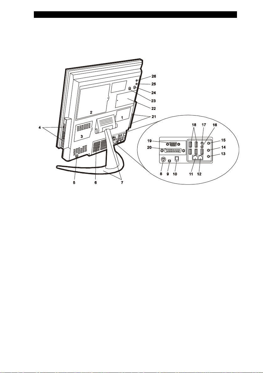
Rear View
1. Mini PCI Card Slot Access Door
The optional mini-PCI-based wireless LAN IEEE802.11b, or
802.11a, or 802.11g card can be installed in this slot to enable
wireless connectivity to other wireless LAN devices. Go to Chapter
3 to learn how to install the optional wireless LAN card.
2. Hard Disk Drive Access Door
The HD drive is located behind this door. Go to Chapter 3 to learn
how to replace the hard disk drive.
3. Memory Expansion Slot Access Door
Additional memory module can be installed in the DIMM sockets to
Page 9

¦
chapter 1 getting to know the basics
1-9
increase system memory. Go to Chapter 3 to learn how to install
additional DIMM module.
4. Multi-Drive Bay
Depending on the factory-installed option, this bay may contain
CD-ROM, CD-RW, Floppy Disk Drive, or Card Reader (which
supports Compact Flash, MicroDrive, SD Memory, Memory Stick.)
5. Power Jack (DC-in)
The DC-out jack of the AC Adapter connects here and powers the
computer.
6. Ventilation Grill
The fan grill is where hot air is vented. Do not block this airway
completely.
7. Stand With a Tilt-able Head
The stand supports the computer. The stand also features a
tilt-able mechanism that allows you to tilt the computer to a
comfortable viewing angle.
8. PS/2 Keyboard / Mouse Port
The PS/2 port is where you connect a keyboard or mouse.
9. Firewire / IEEE1394 Port
You may connect any Fire-wire-ready device to this port. The 4-pin
IEEE1394 connector does not provide power to the attached
device; this port is for data transfer only.
Page 10

¦
chapter 1 getting to know the basics
1-10
10. S/PDIF Port
The special optical port carries digital audio signal. You may
connect an external DTS, AC3, or PCM sound processor / decoder
to this port.
11. Ethernet / LAN Port
The port connects to a network hub via the RJ-45 cable and also
conforms to 10/100Base-TX transmission protocol.
12. Modem Port
This is where you plug the phone jack (RJ-11) for fax/modem
functions.
13. Center Channel / Bass (Subwoofer) Jack
The audio output jack (3.5-mm diameter) is where you connect to
a center speaker through an amplifier and/or to a powered
subwoofer.
14. Rear Speakers Jack
The audio output jack (3.5-mm diameter) is where you connect to
a pair of rear speakers through an amplifier.
15. Front Speakers Jack
The audio output jack (3.5-mm diameter) is where you connect to
a pair of front speakers through an amplifier.
16. Audio Line-in Jack
The Audio Line-in jack (3.5-mm diameter) is where you connect an
external audio source such as a CD Player.
Page 11

¦
chapter 1 getting to know the basics
1-11
17. Microphone Jack
The microphone jack (3.5-mm diameter) is where you connect a
microphone.
18. USB2.0 Port (x5)
The Universal Serial Bus (USB2.0-compliant) port allows you to
connect a wide variety of devices to your computer at a rate of up
to 480 Mbps. This port conforms to the latest USB2.0 plug and
play standard.
19. External VGA Port
The 15-pin VGA analog port is for connecting the external CRT
monitor or projector.
20. Parallel Port
The 25-pin parallel port connects to any parallel-port devices such
as a printer.
21. PC Card Slot (Type II PCMCIA) and Card Eject Button
The slot is where PC Card (Type II PCMCIA) is inserted. Press the
eject button to release the PC Card.
22. TV Tuner / Video Capturing Card Access Door
An optional TV Tuner Card is located behind this door. The
optional tuner module is not a user upgradeable device.
23. S-Video Out (for system with the optional TV Tuner / Cable
Card)
This is where you connect to a TV Set (with compatible S-Video In
port) or to a CRT projector.
Page 12

¦
chapter 1 getting to know the basics
1-12
24. S-Video In (for system with the optional TV Tuner / Cable
Card)
This is where you connect the analog S-Video Out port of the
source device such as a camcorder, a VCR or a DVD player.
Note: Go to TV Tuner and Video Capture section elsewhere in this chapter for a
general description of the TV Tuner function and the associated operational hot
keys.
Note: An application called Power VCR must be installed to view or capture TV /
Cable programs.
25. RCA Video In (for system with the optional TV Tuner / Cable
Card)
This is where you connect the analog Video Out port of the source
device such as a camcorder, a VC or a DVD player.
26. Coaxial Antenna In (for system with the optional TV Tuner /
Cable Card)
This is where you connect the antenna or to a Cable TV box.
Page 13

¦
chapter 1 getting to know the basics
1-13
AC Adapter
1. DC-out Connector
The DC-out connector docks to the power jack (DC-in) on the
computer.
Warning: Do not let water get into the AC adapter
2. LED Lamp
The LED lamp appears green when the unit is plugged into a valid
AC source.
3. Adapter
The adapter converts alternating current into constant DC voltage
for the computer.
4. AC Plug
The AC plug plugs to the AC wall outlet.
Warning: Make sure that you are using a standard 3-prong AC plug with a
ground pin. If not, you may feel a slight tingling sensation when you touch the
computer’s metal parts such as the I/O ports. This is caused by a leakage current
when the AC adapter is not properly grounded via the ground pin. However, the
amount of leakage current is within the safety regulation and is not harmful to the
human body.
Page 14

¦
chapter 1 getting to know the basics
1-14
Remote Control (Optional Device)
If your system comes with a TV Tuner / Video Capturing module, the
remote control can be used to play or record TV programs. You may
need to install a software application called CyberLink Power VCR
before the remote control can be used. The application is installed
automatically when you install the driver for the TV Tuner / Video
Capturing card. See the following illustration for a general description
of the keys.
See section elsewhere in this chapter for TV playback or record
functions or see Power VCR’s help screen for detailed instructions.
Note: Your system may come with a different remote control. Please consult the
user manual in the factory CD-ROM disc.
Page 15

¦
chapter 1 getting to know the basics
1-15
LED Status Indicator
LED Graphic
Indication
Symbol
Green light indicates the optical drive is
being accessed.
Green light indicates the floppy drive
and/or card reader is being accessed.
Green light indicates the hard drive is
being accessed.
Blinking yellow light indicates the
computer is in suspend mode.
Green light indicates the power is on.
Page 16

¦
chapter 1 getting to know the basics
1-16
Graphic Subsystem
Your computer uses a high performance 17-inch active matrix TFT
panel with high resolution and multi-million colors for comfortable
viewing. The world-renowned ATI Mobility Radeon 9000 or
alternatively nVIDIA FX 5400 (NV31) video graphics accelerator with
its dedicated frame buffer (up to 128MB) performs graphic rendering
at a lighting-fast speed.
LCD Brightness Control
?? Using Hot Keys
Press TV+Channel UP (Forward) to increase the brightness.
Press TV+Channel Down (Backward) to decrease the brightness.
(See Page 1-20 for where the keys are.)
?? Using Utility Application
A Qkey utility application allows you to control the LCD backlight.
The Qkey application can be found in the factory CD-ROM
(D:\Utility\Qkey\Setup.exe)
To access the Qkey applet, right-click the Qkey icon in the task tray
and select Brightness.
Click the left button to increase brightness. Click the right button to
decrease brightness.
Page 17

¦
chapter 1 getting to know the basics
1-17
TV-tuner / Video Capturing Functions (Optional Device)
The optional TV-tuner / Video Capturing module allows you to
watch and record TV programs or analog video sources. For
computer with this option, there are three analog video input ports
(Antenna, S-Video In and A/V Video In) on the back of the system.
Note the option is not user-upgradeable.
?? You need to run a utility program called Power VCR in
order to use the card’s function. This program is uploaded
automatically when the driver of the TV Tuner / Video
Capturing card is installed.
?? You can control the basic playback and record functions
via the remote control or the front panel access keys (see
section below); if you want more sophisticated control
functions, you can use the software’s functional menus.
Go to Power VCR’s help screen for detailed instructions.
?? Press TV button and the Power VCR application will start.
Or, simply go to [Start > Programs > Cyberlink Power VCR]
to launch the application.
?? Connect one of the three input ports to an analog video
source or antenna.
?? The option is either NTSC or PAL compliant. Go to [Start >
Programs > TV Card V.3 > Country Configuration] and
select your country from the pull-down menu.
Page 18

¦
chapter 1 getting to know the basics
1-18
?? The front panel keys only works in Windows.
?? For more detail description of the TV functions, please
consult the program’s built-in on-line Help manual.
Page 19

¦
chapter 1 getting to know the basics
1-19
The front panel access keys:
Channel
DOWN
Play /
Pause
Capture
Start /
Stop
Channel
UP
TV
Description of the TV function keys:
TV button: In Windows, pressing the key launches the
Power VCR application.
Play / Pause button: Plays the video files. Press again to
stop playback.
Capture Start / Stop button: Starts recording of the
selected channel. Press again to stop video recording.
Channel UP button: Selects the next channel.
Channel DOWN button: Selects the previous channel.
Page 20

¦
chapter 1 getting to know the basics
1-20
Audio Subsystem
Your computer’s audio subsystem is Sound Blaster Pro-compatible. It
has two stereo speakers and a built-in subwoofer for enhanced bass
response.
Adjusting the Audio Volume in Windows
1. Click the speaker symbol in the task tray in Windows.
2. Drag the volume control bar up or down to adjust the volume.
3. To temporarily silence the speaker without changing the volume
setting, click Mute.
Adjusting the Audio Volume Using the Volume Dial
Rotate the Volume Dial (located to the left bottom edge of the
computer display) to adjust the speaker volume.
Enabling 5.1 Speaker Output
The system supports 6-channel, 5.1 speaker output. Go to [Start >
Control Panel > Sound Effect Manager > Speaker Configuration]
to configure the audio output ports.
Page 21

¦
chapter 1 getting to know the basics
1-21
Sound Effect Adjustment
You can select a special sound effect from the Sound Effect
Manager. Go to [Start > Control Panel > Sound Effect Manager >
Sound Effect] to select the desired sound effect from the pull-down
menu.
Voice Recording
You can use the built-in microphone on the upper edge of the
display panel or an external microphone connected to the Mic-in
audio port on the back of the computer. You will need to use audio
processing software for voice recording. For example, you may
use Microsoft Sound Recorder.
Page 22

¦
chapter 1 getting to know the basics
1-22
How to Enable S/PDIF Digital Output
The computer is equipped with an optical digital audio output port
called S/PDIF. You will need to connect the output port to an
external DTS, AC3, or PCM audio processor in your home audio
system via an optical digital audio cable (not supplied.)
To Enable S/PDIF output, do the following:
1. Double-click the speaker (audio) icon at the right hand
corner of the task bar.
2. On the Volume Control Panel, click [Options > Properties]
and you will see the following box. Check SPDIF and press
OK. This enables SPDIF output.
Page 23

¦
chapter 1 getting to know the basics
1-23
AudioDJ / MP3 Player Functions
Pause
Previous
Backward
The special audio player can work without booting to Windows.
This is called the Standalone Mode and it saves power. The player
will also work in Windows. This is called the Windows Mode.
Standalone (non-Windows) Mode
?? The AudioDJ / MP3 player can function without having
to boot to Windows.
?? You must install the special AudioDJ / MP3 player
program from the factory CD-ROM (D:\Utility\SuperDJ) if you
want to use the player in standalone (non-Windows) mode.
The player searches Audio CD or MP3 CD in the optical drive
first. If no disc is present, it then searches the MP3 tracks
stored in C:\ MP3.
?? Volume adjustment is via the VR dial located at the
bottom left edge of the computer.
?? The track number and playback status are displayed in
the LCM display module.
?? In standalone mode, audio CD playback from the
optical drive is supported.
The front panel access keys:
On
Off
Play
Stop
Repeat
Next
Forward
Page 24

¦
chapter 1 getting to know the basics
1-24
Description of the AudioDJ / MP3 function keys:
MP3 button: Turns the standalone AudioDJ / MP3 player
on. Press and hold for 2 seconds to turn off.
Repeat button: Press to cycle through Repeat One,
Repeat All, Random (or Shuffle) mode. In Repeat One mode,
the current track is repeated continuously until stopped. In
Repeat All mode, all tracks are repeated. In Random (or
Shuffle) mode, tracks are playback at random orders.
Play / Pause button: Press once to start playback. Press
again to pause a track during playback. Press again to
resume playback of the current track.
Stop button: Stops the current track.
Previous / Backward button: During playback, pressing
once returns to the beginning of the current track. Pressing
twice in less than two-second interval returns to the previous
track. Pressing and holding for more than one second rewinds
the current track.
Next / Forward button: During playback, pressing
once advances to the next track. Pressing and holding for
more than one second fast-forwards the current track.
Windows Mode
In Windows, you may launch the MP3 application from the
Programs set to playback MP3 tracks. Note the front panel keys
are re-assigned to other video functions. (Certain keys are used
to operate the TV-tuner function when an optional TV Tuner
module is pre-installed.)
Page 25

¦
chapter 1 getting to know the basics
1-25
Modem
Your computer comes with a 56K V.90 internal fax/modem and a phone
jack (RJ-11), which is located on the left rear side of your computer.
Use a telephone cable to connect the computer to the telephone wall
outlet.
Connecting the Modem
1. Plug one end of the phone line into the modem port located on
the rear side of the computer.
2. Plug the other end of the line into the analog phone wall outlet.
Depending on where your computer is used, you may need to change
settings in the modem. Correct setting will allow you to maintain a stable
connection in a country where its telecommunication system may be
different to others.
To change the modem setting, do the following:
1. Go to [Start > Settings > Control Panel] and double-click on
Modem Settings icon. You will see a similar dialog box.
2. Click on the pull-down menu and select the country where it is
applicable. Click on OK to exit.
Page 26

¦
chapter 1 getting to know the basics
1-26
Ethernet Adapter
Your computer is equipped with a 10/100Base-TX SiS900 PCI Fast
Ethernet network adapter. Connect the active LAN cable to the RJ-45
LAN port located on the left rear side of the computer. This allows you
to access and transmit data in the local area network.
Connecting to the Network
Use Unshielded Twisted Pair (UTP) Ethernet cable only.
1. Insert one end of the UTP cable into the network connector
until the connector snaps securely into the receptacle.
2. Either connect the other end of the cable to an RJ-45 jack
wall outlet or to an RJ-45 port on a UTP concentrator or hub in the
network.
Cabling Restriction for Networks
The following restrictions should be observed for 100BASE-TX
networks:
? The maximum cable run length is 100 meters.
?? For 100-Mbps operations, use Category 5 wiring and
connections.
Note: Consult Windows manual and / or Novell Netware user’s guide for the
software installation, configuration, operation of the network.
 Loading...