

Page 1
How to Read this Manual:
This manual is written specifically for people who would like to build their PCs.
A color map is to help you easily find the correct installation component and peripherals positions on the mainboard and
PC case. Those locations, connectors and jacks, are marked with a corresponding color. This allows you to identify the
correct installation locations of related parts and avoid mistakes during install ation. Please refer to the following table.
No matter whether or not you are skilled in computer assembly, using the color map in this manual, you can easily
assemble a computer.
How to Read this Color Map?
This color map is not a real map but a color table that shows the compone nt installation sequence and the corresponding
colors of the individual components. Following the sequence and matching the colors, you can easily assemble your
computer. By referring to the colo r table and check all colors listed to ensure all components are inst alled. It is easy to
identify any missing part(s) or incorrectly installed components
Sequ
ence
***”W”= White
There are three major columns in this table. The first column lists the component names; the second lists the colors of the
lines/connectors connecting certain components. The third is for confirmation purpose, you can check the check box after
completing the component installation.
The proper use of this table (from now, referred to as “Color Map”) provides you with a simple and mistake-free installation
process of this PC. If anything goes wrong, you can identify the problem(s) very quickly.
In addition, at the beginning of each section detailing each part in st allation, there is a color cha rt showing the right pl ace for
the corresponding connectors on the mainboard and giving you an idea of what p arts need to be installed and their
corresponding locations after installation.
Names of Parts Color Completion Sequ
ence
1 Cooling Fan Power
Cord
2 Memory 6 Monitor
3 Hard Drive Cable 7 ATX Power W
4 Optical Device
Drive Cable
5 External Power
8 12V Power W
Names of Parts Color Completion
Supply
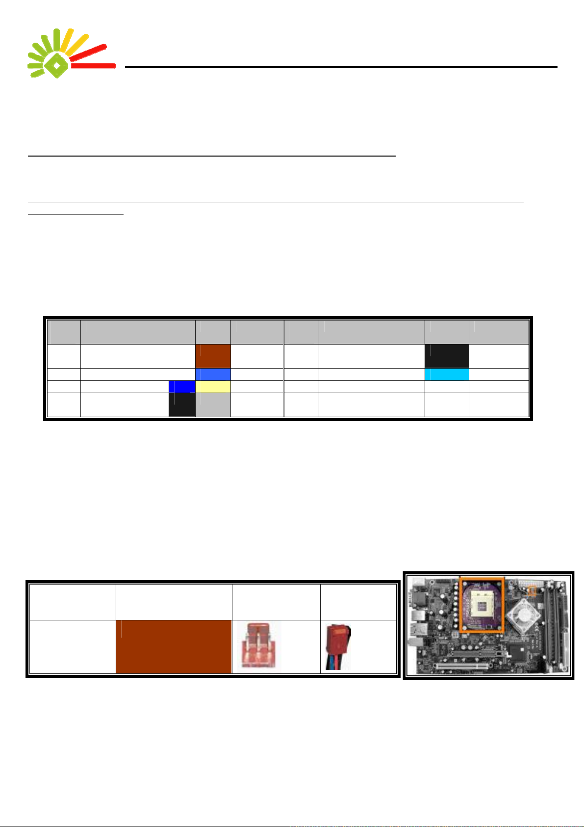
Color Chart and Installation Locations:
Name Corresponding
Color
Power Line for
Cooling Fan
Also, at the beginning of each section, the locations of the installation mentioned in
that section are marked on the mainboard picture, and the colors mentioned are also listed.
Furthermore, the locations of related sockets on the mainboard are shown along with
the appearance and locations of related parts.
1
Socket Plug
Page 2
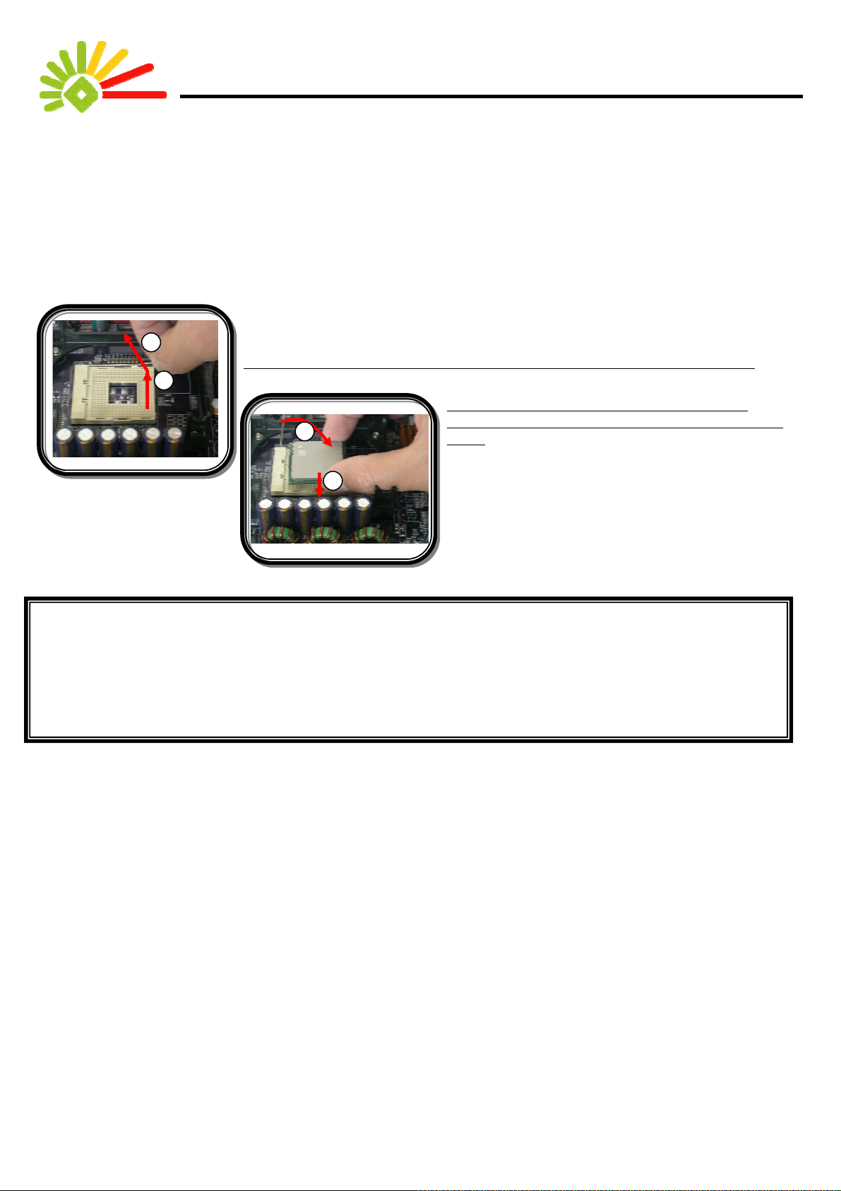
What the Arrowhead stands for? :
Finally, you have to understand what the arrowheads in the pictures stand for. Each arrowhead represents the direction of
an action. The whole installation process is executed through actions. Each part is installed through different actions. An
example shown below illustrates the details of actions and their sequen ces:
2
Push the handlebar outwards and pull it up according to the direction of the arrow.
1
Insert CPU into CPU Socket, and then fixed the
1
2
handlebar downward according to the direction of the
arrow.
1
Notes:
1. All contents in this manual are copyright protected property. Any duplication will violate the law.
2. The design of Color Map is undergoing patent application. Copying without permission will be
penalized with patent violation.
2
Page 3

Contents:
How to Read this Manual:.............................................................................................................1
How to Read this Color Map?................................................................................................1
Color Chart and Installation Locations: ................................................................................1
What the Arrowhead stands for? :..........................................................................................2
Contents:.......................................................................................................................................3
Starting installation........................................................................................................................4
Open the Case and Install the Mainboard.............................................................................. 4
Installing a CPU & a Heat Sink and System Fan ...................................................................4
Installing a Memory module...................................................................................................7
Connecting the mainboard power cord.................................................................................. 7
Connecting the System Fan Power line.................................................................................8
Installing IDE Cables for Hard Drives and Optical Device Drive ............................................8
The Installation of Hard Disks..............................................................................................10
The Installation of Optical Device Drives.............................................................................. 11
The Installation of the PC case............................................................................................12
The Installation of External Power Supply ........................................................................... 13
The Installation of Monitor....................................................................................................13
The Installation of a Keyboard, Mouse and FM antenna......................................................14
The Installation of Speakers.................................................................................................15
3
Page 4
Starting installation
Open the Case and Install the Mainboard
Installation Notes:
1. The case of aluminum has a refined appearance. Since aluminum is a very soft material, an e xtra treatment of
hardness has been applied to the case. However, such treatment still can not prevent the case from scratches.
Therefore, we suggest you to place a piece of clean paper board or soft pad and then place the PC on top of the
board or pad. Even the dismantled cover also needs to be placed on p a ds to avoi d scratches by improper placem ent.
2. The mainboard contains very complicated pieces of electronic part. Though a proper protection has been applied, it
may still be harmed or damaged by unexpected static electricity. Therefore, we suggest you to put on an anti-static
wristlet (please refer to the manual of the wristlet for further instruction). If you do not have any anti-static wristlet, you
should wear a nonconductive glove. Though the glove can causes inconvenience in computer assembly, it can
provide effective protection to the mainboard. If you do not even have a nonconductive glove, we suggest you to try to
use bare hands to touch a large-scaled metal product before starting the installation. This can effectively remove the
static on your hands, achieving a basic protection for the mainboard.
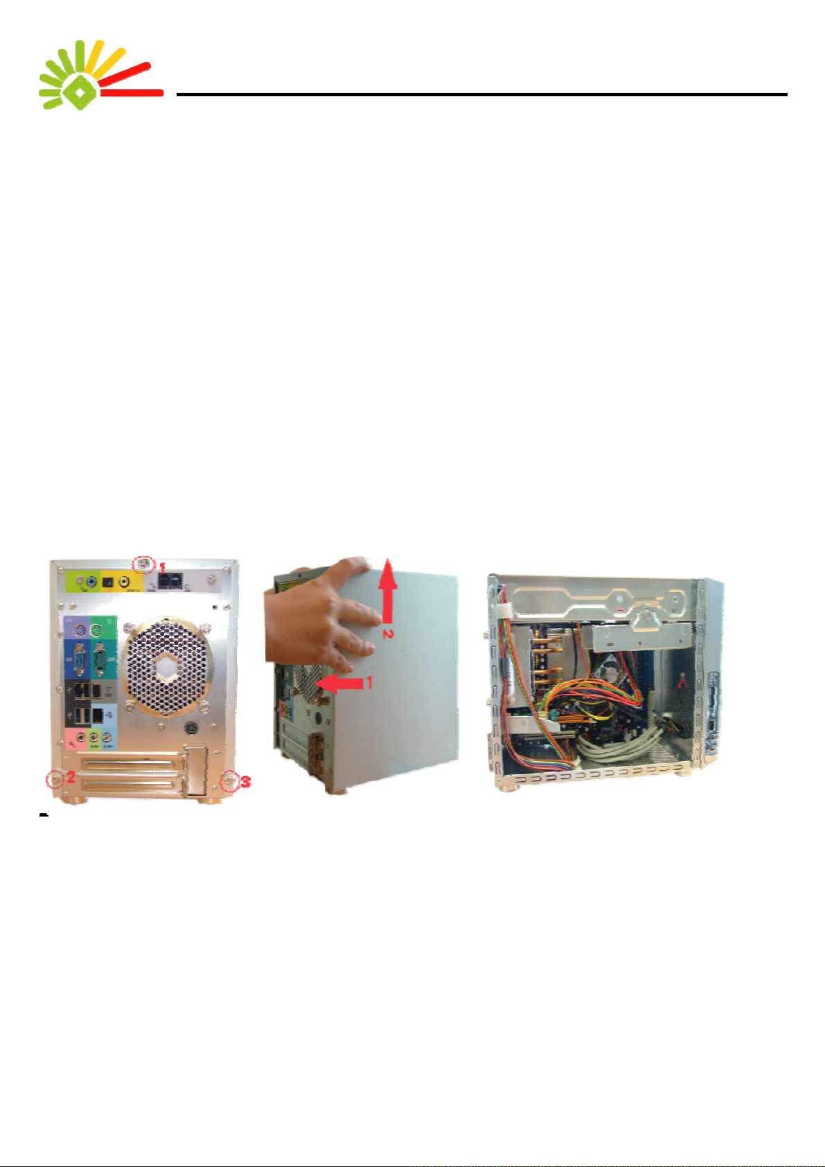
Opening the case:
A. Unscrew three hand-screw on the
back.
B. Pull the cover backward and then
upward.
C. Remove the cover and then the
mainboard is accessible.
Installing a CPU & a Heat Sink and System Fan
The Installation Locations and the Colors
4
Page 5
Name Corresponding
Socket Plug
Color
Power Line for Heat
Sink and System Fan
Installation Notes:
1. A CPU can only be inst alled in a p articular dire ction, which can be sure by aligning the notch at the corner of CPU and
the notch at the corner of the socket (shown in the enlarged picture of the second operation illustration). Please note
that the pins of CPU are very fragile. If the CPU cannot smoothly install into the socket, two possible situations might
have occurred. First, some of the pins are bended. Please use tools to carefully straighten the pins. The se cond
possibility is that the direction is wrong. Please remember to align those two notches of the CPU and the socket
correctly.
2. This PC comes with a cooling fan, a high performance Smart Fan. This Fan can effectively exhausts heat in the PC
case, and can keeps the PC in the best noise-free st ate (Some devices, like hard disk drives and CD-ROM drives,
can also cause noise. Since those devices are designed and made by other manufacturers, we can only reduce but
cannot totally control the noise caused by the devices.). However, for compatibility, this series of PC case is specially
designed for mainboards that supports Pentium 4. Therefore, a cooling system designed for AMD CPU cannot be
installed into and worked with this PC. Please use the cooling system that comes with this PC to ensure the
effectiveness of heat exhausting, which provides the stability of the PC.
3. The cooling fan is designed with a locking handle that sticks out of it. Please make sure the handle is directed to the
other side of memory slots. A wrong direction will keep you from installing a hard disk.
Installing the CPU
安裝散熱裝置的方法
A. Unscrew those four screws
around the ventilation opening.
B. Flat the EZ-Buddie 2, locate the heat
pipe.
C. Remove the fan cover on the heat
pipe.
5
Page 6

D. Push the clips in the arrow
direction to remove them
G. Pull the CPU level upward
and then rightward.
E. Af ter removing the clips on both
sides, pull up the hest pipe at a 30
degree angle.
H. Align and insert the CPU pins into the
socket. The fool-proof is on the upper right
corner.
F. There is a piece of black pad on top of
the CPU. Please remove and dispose
the pad.
I. Apply some cooling gel e v enly on
the top of the CPU and then reinstall
the heat pipe.
J. Reinstall the fan. K. Fix with the clips. L. Plug the fan power cord back to the
mainboard.
M. Screw the four screws to complete this CPU and heat sink device
installation.
6
Page 7

Installing a Memory module
The Installation Locations and the Colors
Name Corresponding Color Slot Plug
Memory
Installation Notes:
1. A memory module can only be installed into a slot in one way.
Please align a notch at the bottom of the memory module with
a protrusion, a foolproof device, in the slot.
Installing the Memory Module
A. Press down both clips by the arrow direction.
B. Align the memory module to the foolproof pin and
insert the module vertically.
Connecting the mainboard power cord
The Installation Locations and the Colors
7
Page 8

Name Corresponding
Socket Plug
Color
ATX Power
White
12V Power White
Installation Notes:
1. Your EZ-Buddie 2 comes with one stan dard power supply module and one 12V power supply module, forming a
stable power system. The plugs and sockets for both modules adopt the fool-proof design. This prevents you from
connecting these plugs and socket in wrong direction.
Connecting the System Fan Power line
The Installation Locations and the Colors
Name Corresponding
Color
System Fan
White
Socket Plug
Installation Notes:
1. Each sockets and plugs of the system fan comes with a foolproof design, allowing the plugs only can be connected to
the sockets in one way.
Installing IDE Cables for Hard Drives and Optical Device Drive
The Installation Locations and Colors
8
Page 9

Name Corresponding
Socket Plug
Color
Hard Disk
Cable
(ATA100)
Optical Device
Drive Cable
(ATA66)
Installation Notes:
1. This installation only involves connecting one end of the cables for hard drives and Optical Device Drive to the
mainboard. The other end of the cables will be connected to hard disks and Opti cal Device Drive.
2. Since the transmission speeds of the hard drives and the Optical Device are dif f erent, we have used two cables with
different transmission speeds. The yellow cable with blue plugs, for ATA100, is for hard disks; the cable with another
color is, for ATA66, for Optical Device drives.
3. Similarly, both the cables for hard disks and Optical Device have foolproof-designed plugs, allowin g the plugs only
can be connected to the mainboard in one way.
Connecting the Cable for HDD Connecting the Cable for Optical Device Drives
Both A T A100
and A T A66
have this
9
Page 10

The Installation of Hard Disks
The Installation Locations and the Colors
Name Corresponding
Socket Plug
color
Hard Disk
Lines(ATA100)
Installation Notes:
1. For the convenience in installation, we strongly recommend you to install the hard drives first and then the Optical
Device Drives. If you fail to follow this sequence, it is still possible and more difficult to install hard drives later.
2. Please be aware that the cables connected to hard drivers are yellow.
Installing the Hard Drives
A. Unscrew the screw and take out
the hard-disk bracket.
10
B. Put your hard disk into the bracket.
C. Screw the hard disk to the both
side of the bracket.
E. Insert one end of the yellow cable into the
blue IDE slot by the direction of the foolproof
device.
F. Insert the other end of the yellow cable into
the hard drive by the direction of the
foolproof device, and the power cable with
the red line on the inside.
D. Screw the bracket back to same
place.
Page 11

The Installation of Optical Device Drives
The Installation Locations and Colors
Name Correspondi
Socket Plug
ng Color
Optical Device
Drive Cable
(ATA66)
Installation Notes:
1. Ensure the cables connected to Optical Device Drives are gray.
Installing Optical Device Drives
A. Put ODD into the case in a
horizontal position.
B. Push the drive by the arrow
direction into position
C. Open the ODD door and adjust the
stud to the ODD Eject Button.
11
Page 12

D. We strongly suggest that remove the
ODD Bezel from the Optical Device
Disk
E. Screw the drive to the left and right
sides with two screws each.
.
D. Plug the one end of the gray
flat-cable into the white IDE by the
direction of the foolproof design.
E. Plug the other end of the gray
flat-cable into the driver by the
direction of the foolproof design.
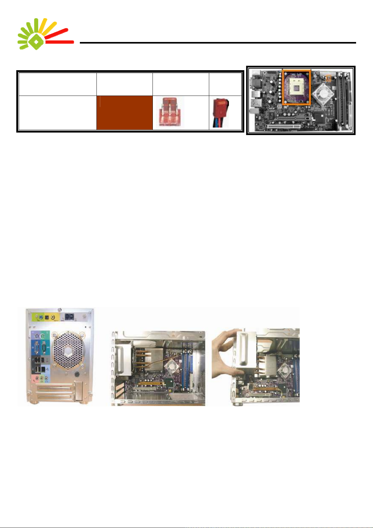
The Installation of the PC case
Installing the PC case
F. Plug the power cord with the red
line on the inside.
This clearance is about
5cm. A longer or shorter
clearance may causes
inconvenience in
installation.
A. Lay the cover on the chassis leaving a 5cm clearance
from the front panel, and then push it forward to lock the
cover.
12
B. Screw the cover with three screws and finish with the
hardware installation.
Page 13

The Installation of External Power Supply
The Installation Locations and Colors
Name Corresponding
Color
External Power
Supply
Socket Plug
Installation Notes:
1. This PC mainly uses an external power supply as its power source. In addition to this PC, you also have to install an
external power supply; otherwise, this PC will not be able to function.
2. The installation of the external power supply has two steps. Firstly, you need to connect the power cord with the
external power supply, and then connect the other end of the power cord to the power socket.
3. Secondly, you have to connect the external power supply to the PC. In this step, please note that the joints
connecting the external power supply and the PC are foolproof-designed. Please make sure the side with an arro w
mark is facing upwards.
Installing the External Power Supply
平面朝上
The Installation of Monitor
The Installation Locations and Colors
13
Page 14

Name Corresponding
Color
Monitor
Socket Plug
Installation Notes:
1. Computer monitors usually have an independent power source. Please follow the
instruction in the manual of the monitor for monitor installation.
2. This PC offers no extra power source for monitors, and requires a monitor that comes
with an independent power source.
3. Before a monitor is used, please follow the instructions in the monitor manual to t urn o n
the power; otherwise, the monitor will display nothing.
The Installation of a Keyboard, Mouse and FM antenna
Installation Notes:
1. Keyboards and mice come with two connector types: PS/2 and USB. These two connector types have dif f erent
installation procedures. It is recommended that you use a mouse and a keyboard with the same connectio n type.
However, a keyboard and a mouse having different connection types can still be used on this PC.
2. Your EZ-Buddie 2 comes with a exclusive FM antenna. You can find it in the accessory package.
Connecting a PS/2 Keyboard/Mouse Connecting a USB Keyboard Connecting an FM antenna
14
Page 15

The Installation of Speakers
Installation Notes:
1. There are three kinds of Speakers available: 2-Channel, 4-Channel, and 5.1-Channel. This PC can support up to
5.1-Channel speakers (for windows only.).
2. Both 4 Channel and 5.1 Channel speakers are designed with a front channel and a rear channel. Connect these
speakers to the correct jacks (show in the following illustration) for correct multi-channel outputs.
3. Both 4 Channel and 5.1 Channel speakers are designed with both a front channel and a rear channel. These
speakers can offer surrounded sound effect with the proper speaker arrangement. Please see the speaker manual.
4. The following illustration shows the function of each labeled speaker jack in this PC. You can follow the labels and the
instructions in the speaker manual to correctly connect the speakers to this PC.
5. For the 2-Channel speakers, just connected them to the audio jack for front speakers.
Mic. /Central &
Sub-Woofer
Line-In/Front
Speakers
Line-Out/Rear
Speakers
15
 Loading...