

Page 1

i
Page 2

Page 3

Preface
©Copyright 2007
©
All Rights Reserved.
The information in this document is subject to change without prior
notice in order to improve reliability, design and function and does
not represent a commitment on the part of the manufacturer.
In no event will the manufacturer be liable for direct, indirect,
special, incidental, or consequential damages arising out of the
use or inability to use the product or documentation, even if
advised of the possibility of such damages.
This document contains proprietary information protected by
copyright. All rights are reserved. No part of this manual may be
reproduced by any mechanical, electronic, or other means in any
form without prior written permission of the manufacturer.
Limitation of Liability
While reasonable efforts have been made to ensure the accuracy
of this manual, the manufacturer and distributor assume no liability
resulting from errors or omissions in this manual, or from the use of
the information contained herein.
Notices
Federal Communications Commission Radio Frequency
Interference Statement
This equipment has been tested and
found to comply with the limits for a Class B digital device,
pursuant to Part 15 of the FCC Rules. These limits are
designed to provide reasonable protection against harmful
interference in a residential installation. This equipment
generates, uses, and can radiate radio frequency energy and
if not installed and used in accordance with the instruction
manual may cause harmful interference to radio
communications. However, there is no guarantee that
interference will not occur in a particular installation.
i
Page 4

If this equipment does cause harmful interference to radio or
television reception, which can be determined by turning the
equipment off and on, the user is encouraged to try to correct
the interference by one or more of the following measures:
• Reorient or relocate the receiving antenna
• Increase the separation between the equipment and receiver
• Connect the equipment into an outlet on a circuit different from
that to which the receiver is connected
Consult the dealer or an experienced radio TV technician for help.
This device complies with Part 15 of the FCC Rules. Operation is
subject to the following two conditions: (1) This device may not
cause harmful interference, and (2) this device must accept any
interference received, including interference that may cause
undesired operation.
FCC Caution: Any changes or modifications not expressly
approved by the party responsible for compliance could void
the user's authority to operate this equipment.
Notice:
Changes or modifications not expressly approved by the party
responsible for compliance could void the user’s authority to
operate the equipment. Shielded interface cables and a nonshielded AC power cord must be used in order to comply with
emission limits.
ii
Page 5

Table of Content
ATTENTION: TEACHERS, PARENTS AND ADULT SUPERVISORS.................1
1. AGENCY REGULATORY NOTICES................................................3
MODIFICATIONS...................................................................................4
CONNECTIONS TO PERIPHERAL DEVICES.............................................. 4
EUROPEAN NOTICE .............................................................................4
CANADIAN NOTICE...............................................................................5
ATTACHMENT LIMITATIONS STATEMENT................................................5
POWER CORD REQUIREMENT ..............................................................6
BATTERY PACK SAFETY.......................................................................8
LITHIUM BATTERY WARNING / BRIDGE BATTERY WARNING ......................9
2. GETTING TO KNOW THE BASICS ...............................................11
TOP VIEW .........................................................................................11
SYSTEM & POWER STATUS INDICATORS.............................................15
FUNCTION KEYS (QUICK KEYS).......................................................... 16
WINDOWS* KEYS...............................................................................17
EMBEDDED NUMERIC KEYPAD ...........................................................17
ABOUT THE DISPLAY SWITCHER UTILITY.............................................18
ADJUSTING THE DISPLAY BRIGHTNESS ...............................................18
EXTENDING THE LIFE OF THE TFT DISPLAY DEVICE ............................19
OPENING AND CLOSING THE DISPLAY PANEL ...................................... 19
ADJUSTING THE VOLUME MANUALLY ..................................................19
ADJUSTING THE AUDIO VOLUME IN OPERATING SYSTEM ..................... 19
VOICE RECORDING............................................................................19
CONNECTING TO THE NETWORK.........................................................20
CABLING RESTRICTION FOR NETWORKS .............................................20
3. BATTERY POWER & POWER MANAGEMENT ...........................21
LITHIUM-ION BATTERY .......................................................................21
BATTERY LOW-POWER WARNING.......................................................21
CHARGING THE BATTERY AND CHARGING TIME ................................... 22
CHECKING THE BATTERY LEVEL .........................................................22
PROLONGING THE BATTERY’S LIFE AND USAGE CYCLES...................... 22
STANDBY SUSPEND ...........................................................................23
HIBERNATE SUSPEND ........................................................................23
iii
Page 6

4. BIOS SETUP AND SECURITY FEATURE.....................................25
ENTERING THE BIOS SETUP SCREEN ................................................25
BIOS ACTION KEYS ..........................................................................26
MAIN SETUP ..................................................................................... 27
ADVANCED SETUP.............................................................................28
SECURITY SETUP ..............................................................................29
BOOT SETUP.....................................................................................30
EXIT SETUP ......................................................................................32
5. UPGRADING YOURCOMPUTER..................................................33
6. TROUBLE SHOOTING ..................................................................43
NO SPEAKER OUTPUT ........................................................................44
SOUND CANNOT BE RECORDED ..........................................................44
THE HARD DRIVE IS MAKING ABNORMAL WHINING NOISES .....................44
THE HARD DISK DRIVE HAS REACHED ITS CAPACITY ............................. 45
THE HARD DISK TAKES LONGER TO READ A FILE...................................45
THE DISPLAY PANEL IS BLANK WHEN THE SYSTEM IS TURNED ON ..........45
THE SCREEN IS DIFFICULT TO READ ....................................................45
THE SCREEN FLICKERS ......................................................................45
THE BUILT-IN TOUCH PAD PERFORMS ERROTICALLY .............................45
THE BUILT-IN KEYBOARD ACCEPTS NO INPUT .......................................45
THE CHARACTERS ON THE SCREEN REPEAT WHILE I TYPE. ...................46
THE POST DOES NOT SHOW AN INCREASED MEMORY CAPACITY WHEN
YOU HAVE ALREADY INSTALLED ADDITIONAL MEMORY
..........................46
THE O/S ISSUES AN INSUFFICIENT MEMORY ERROR MESSAGE DURING
OPERATION
.......................................................................................46
THE ETHERNET ADAPTER DOES NOT WORK ......................................... 46
THE ETHERNET ADAPTER DOES NOT APPEAR TO OPERATE IN THE
100MBPS TRANSMISSION MODE .........................................................46
THE COMPUTER BECOMES HOT ..........................................................47
THE PROGRAM APPEARS STOPPED OR RUNS VERY SLOWLY .................47
THE USB DEVICE DOES NOT WORK ....................................................47
APPENDIX: SPECIFICATION....................................................................49
iv
Page 7

AAtttteennttiioonn:: TTeeaacchheerrss,, PPaarreennttss aanndd
AAdduulltt SSuuppeerrvviissoorrs
Please ensure that students understand the following:
• Emphasize to student that this device is an educational tool
and not a toy. The computer, power supply, battery pack or
power cord should not be dropped, crushed, stepped on or
otherwise abused.
• This product is intended for school age children, ages 6 and up.
• Ensure students understand the safe and proper handling of
power cord and power supply. Misuse could result in serious
injury.
• Use caution when using this computer around younger children.
Keep power cords away from younger children. Keep small
accessories away from younger children. If computer is
damaged, keep any resulting small parts (such as a keyboard
key) away from younger children and report damage or loose
parts to their teacher, parent or adult supervisor, immediately.
• The teacher, parent or adult supervisor should periodically
inspect the computer, power supply and power cord for
damage and replace, if necessary.
• Students should report any damage or loose parts to their
teacher, parent or adult supervisor, immediately.
• Caution students to avoid using device in wet conditions and to
protect the unit when carrying in wet conditions.
• When cleaning the unit, clean only with a slightly damp soft
cloth. Do not pour liquid onto the unit. Do not clean while
computer is “on” or plugged into wall socket.
• Do not leave PC plugged in or “on” when enclosed in a non-
vented container, such as a school backpack, as overheating
may occur.
• The most suitable time for students to use the PC on their lap
not exceeding 30 minutes and take a 5 minutes break.
s
1
Page 8

2
Page 9

11.. AAGGEENNCCYY RREEGGUULLAATTOORRYY
NNOOTTIICCEESS
Federal Communications Commission Notice
This equipment has been tested and found to comply with the
limits for a Class B digital device, pursuant to Part 15 of the FCC
Rules. These limits are designed to provide reasonable protection
against harmful interference in a residential installation. This
equipment generates, uses, and can radiate radio frequency
energy and, if not installed and used in accordance with the
instructions, may cause harmful interference to radio
communications. However, there is no guarantee that interference
will not occur in a particular installation. If this equipment does
cause harmful interference to radio or television reception, which
can be determined by turning the equipment off and on, the user is
encouraged to try to correct the interference by one or more of the
following measures:
• Reorient or relocate the receiving antenna.
• Increase the separation between the equipment and the
receiver.
• Connect the equipment into an outlet on a circuit different from
that to which the receiver is connected.
• Consult the dealer or an experienced radio or television
technician for help.
This transmitter must not be colocated or operating in conjunction with any other antenna or
transmitter.
FCC Radiation Exposure Statement:
This equipment complies with FCC radiation exposure limits
set forth for an uncontrolled environment. This equipment
should be installed and operated with minimum distance
19cm between the radiator & your body
3
Page 10

Modifications
The FCC requires the user to be notified that any changes or
modifications made to this device that are not expressly approved
by the Manufacture may void the user’s authority to operate the
equipment.
Connections to Peripheral Devices
Connections to this device must be made with shielded cables with
metallic RFI/EMI connector hoods to maintain compliance with
FCC Rules and Regulations.
Declaration of Conformity
This device complies with Part 15 the FCC Rules. Operation is
subject to the following two conditions: (1) this device may not
cause harmful interference, and (2) this device must accept any
interference received, including interference that may cause
undesired operation.
European Notice
Products with the CE Marking comply with both the EMC Directive
(89/336/EEC) and the Low Voltage Directive (73/23/EEC) and
R&TTE Directive (1999/5/EC) issued by the Commission of the
European Community.
Compliance with these directives implies conformity to the
following European Norms:
• EN55022: 1998+A1: 2000+A2: 2003, CLASS B
• EN61000-3-2: 2000
• EN61000-3-3: 1995+A1: 2001
• EN55024: 1998+A1: 2001+A1: 2003
• IEC61000-4-2: 2001
• IEC61000-4-3: 2002+A1: 2002
• IEC61000-4-4: 1995+A1: 2000+A2:2001
• IEC61000-4-5: 2001
• IEC61000-4-6: 2001
• IEC61000-4-8: 2001
• IEC61000-4-11: 2001
• EN50082 (IEC801-2, IEC801-3, IEC801-4) Electro-magnetic
Immunity
4
Page 11

• EN 300 328-2, EN 300 328-1, EN 301 489-1, EN 301 489-17
(ETSI 300 328, ETSI 301 489) Electro-magnetic Compatibility
and Radio Spectrum Matter.
• TBR21 (ETSI TBR21) Terminal Equipment.
• EN60950 (IEC60950) I.T.E. Product Safety
Canadian Notice
This digital apparatus does not exceed the Class B limits for radio
noise emissions from digital apparatus as set out in the radio
interference regulations of the Canadian Department of
Communications.
Le present appareil numerique nemet pas de bruits
radioelectriques depassant les limites applicables aux appareils
numeriques de Classe B prescrites dans le reglement sur le
brouillage radioelectrique edicte par le Ministere des
Communications du Canada.
Attachment Limitations Statement
This equipment meets
telecommunications network protective, operational and
safety requirements as prescribed in the appropriate Terminal
Equipment Technical Requirements document(s).
This is confirmed by marking the equipment with the Industry
Canada certification number. The Department does not guarantee
the equipment will operate to the user's satisfaction.
Before installing this equipment, users should ensure that it is
permissible to be connected to the facilities of the local
telecommunications company.
The equipment must also be installed using an acceptable method
of connection. The customer should be aware that compliance with
the above conditions may not prevent degradation of service in
some situations.
Repairs to certified equipment should be coordinated by a
representative designated by the supplier. Any repairs or
alterations made by the user to this equipment, or equipment
malfunctions, may give the telecommunications company cause to
request the user to disconnect the equipment.
5
Page 12

Users should ensure for their own protection that the electrical
ground connections of the power utility, telephone lines and
internal metallic water pipe system, if present, are connected
together. This precaution may be particularly important in rural
areas.
Users should not attempt to make such
connections themselves, but should contact the appropriate
electric inspection authority, or electrician, as appropriate.
Power Cord Requirement
The power cord supplied with the AC adapter should match the
plug and voltage requirements for your local area. Regulatory
approval for the AC adapter has been obtained using the power
cord for the local area.
However, if you travel to a different area and need to connect to a
different outlet or voltage, you should use one of the power cords
listed below. To purchase a power cord (including one for a country
not listed below) or a replacement AC adapter, contact your local
dealer.
U.S. and Canada
• The cord set must be UL-Listed and CSA-Certified or C-UL
Listed.
• The minimum specifications for the flexible cord are (1) No. 18
AWG, (2) Type SJ, and (3) 3-conductor.
• The cord set must have a rated current capacity of at least 10
A.
• The attachment plug must be an earth-grounding type with a
NEMA 5-15P (15A, 125V) or NEMA 6-15P (15 A, 250V)
configuration.
Japan
• All components of the cord set (cord, connector, and plug)
must bear a “PSE” mark and registration number in
accordance with the Japanese Dentori Law.
• The minimum specification for the flexible cord are: (1) 0.75
2
mm
conductors, (2) Type VCT or VCTF, and (3) 3-conductor.
• The cord set must have minimum rated current capacity of 7 A.
6
Page 13

• The attachment plug must be a two-pole, grounded type with a
Japanese Industrial Standard C8303 (15 A, 125 VAC)
configuration.
Other Countries
• The cord set fittings must bear the certification mark of the
agency responsible for evaluation in a specific country.
Acceptable agencies are:
BSI (UK)
OVE (Australia)
CEBEC (Belgium)
SEMKO (Sweden)
FIMKO (Finland)
DEMKO (Denmark)
NEMKO (Norway)
SETI (Finland)
EANSW (Australia)
SEV (Switzerland)
IMQ (Italy)
UTE (France)
CCC (China)
PSB (Singapore)
PSE (Japan)
BSMI (Taiwan)
B (Polish)
VDE (Germany)
SASO (Saudi Arabia)
• The flexible cord must be of a HAR (harmonized) type HO5VV-
F 3-conductor cord with a minimum conductor size of 0.03
square inches.
• The minimum specification for the flexible cord for Class II
product are: (1) 2X0.75 mm
2
conductors, (2) 2-conductor cord.
• The cord set must have a current capacity of at least 10 A and
a nominal voltage rating of 125 / 250 VAC.
MODEL E07EIx IS DESIGNED TO USE
WITH THE FOLLOWING AC ADAPTER MODEL ONLY
Manufacture: LI SHIN INTERNATIONAL ENTERPRISE CORP.
Model: 0335C2065 (65W), 0335A2065 (65W), 0225C2040 (40W)
Manufacture: HIPRO
7
Page 14

Model: HP-OK065E03 (65W), HP-OK065E13 (65W)
Battery Pack Safety
• The battery pack is intended to use only with this notebook.
• The battery pack is not replaceable by the end user. Only
qualified service technicians should replace the battery pack.
• Do not disassemble the pack.
• Do not dispose of the battery pack in fire or water.
• To avoid risk of fire, burns, or damage to your battery pack, do
not allow a metal object to touch the battery contacts.
• Handle a damaged or leaking battery with extreme care. If you
come in contact with the electrolyte, wash the exposed area
with soap and water. If it contacts the eye, flush the eye with
water for 15 minutes and seek medical attention.
• Do not charge the battery pack if the ambient temperature
exceeds 45℃ (113℉).
• To obtain a replacement battery, contact your local dealer.
• Do not expose the battery pack to high storage temperatures
(above 60℃, 140℉).
• When discarding a battery pack, contact your local waste
disposal provider regarding local restrictions on the disposal or
recycling of batteries.
• Use only supplied AC Adapter for charging.
Danger of explosion if battery is
incorrectly replaced. Only qualified service technicians
should replace and discard the battery pack. Replace only
with same or equivalent type recommended by the
manufacturer. Discard used batteries according to the
manufacturer’s instructions or local laws.
Explisionsgefahr bei unsachgernazen
Austausch der Batterie. Ersatz nur durch denselben oder
einem vom Hersteller empfohlenem ahnlichen Typ.
Entsorgung gebrauchter Batterien navh Angaben des
Herstellers.
8
Page 15

Lithium battery warning / Bridge battery warning
This computer contains a lithium battery to power the clock and
calendar circuitry.
Danger of explosion if battery is
replaced incorrectly. Replace only with the same or equivalent
type recommended by the manufacturer. Discard used
batteries according to the manufacturer’s instructions.
Il y a danger d’xplosion s’il y a
remplacement incorrect de la batterie. Remplacer uniquement
avcc unc batterie du meme type ou d’un type recommande
par le constructer. Mettre au rebut les batteries usagees
conformement aux instructions du fabricant.
Explosionsgefahr bei unsachgemBen
Austausch der Batterie Ersatz nur durch denselben oder
einem vom Hersteller empfohlenem ahnlichen Typ.
Entsorgung gebrauchter Batterien nach Angaben des
Herstellers.
Der Arbeitsplatzbezogene Schalldruckpegel nach DIN 45 635
betragt 70dB (A) oder weniger.
Zum Netzanschlua dieses Gerates ist eine geprufte Leitung zu
verwenden. Fur einen Nennstrom bis 6A und einem Gerategewicht
groBer 3kg ist eine Leitung nicht leichter als (1)H05VV-F, 3G,
0.75mm
2
(2)2X0.75 mm2 conductors einzusetzen.
Die Steckdose muB nahe dem Gerat angebracht und leicht
zuganglich sein.
This part is hot. Be careful.
Diese Flachewird sehr heiss.
When you see this symbol, be careful as this spot may be
very hot.
When you see this symbol, be careful as this spot may be very hot.
The heat is generated from the CPU.
9
Page 16

10
Page 17
22.. GGEETTTTIINNGG TTOO KKNNOOWW TTHHE
System At A Glance
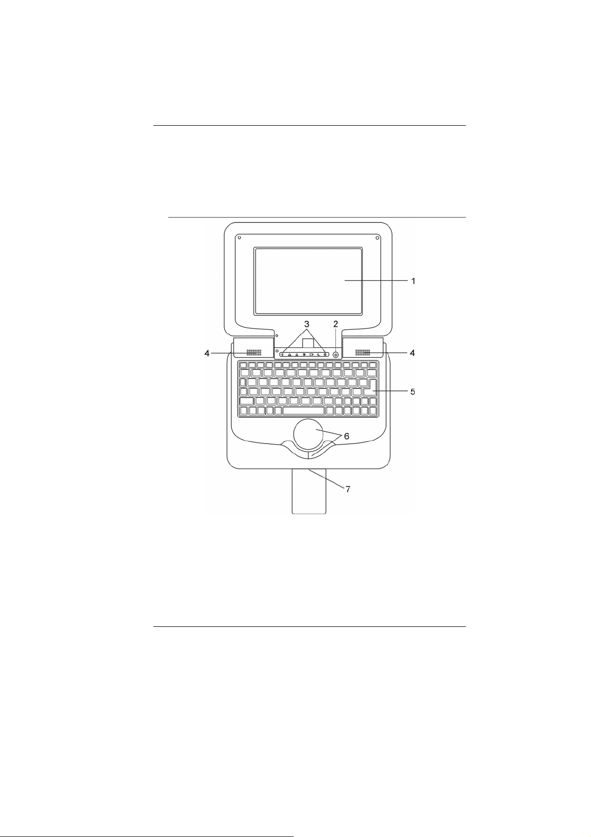
Top View
E
BBAASSIICCSS
1. LCD Display
The panel is where the system content is displayed.
2. Power / Suspend Button
The power/suspend button turns the notebook on and off
and it also acts as a system suspend key.
Press momentarily to turn on the system.
Press and hold for at least four seconds to turn off the
system.
11
Page 18
Press the power/suspend button again to return from the
suspend mode. (See Chapter 3 for more details on
system suspend function.)
When the system is in Suspend Mode, the
status indicator shows green light.
3. LED Status Indicator
The LED Status indicators reveal the status of these
functions: Numeric keypad, cap lock, WLAN module
enabling and disabling and also the data activities. (See
the LED Status Indicator Section for details.)
The LED Status indicators also reveal the status of the
system power state and battery-charging state. See the
LED Status Indicator Section for details.
4. Built-in Stereo Speakers
The built-in speakers output the sound in stereo.
5. Keyboard
The keyboard is used to enter data. (See Keyboard
Section for details.)
6. Touch Pad
The touch pad is a built-in pointing device with functions
similar to a mouse.
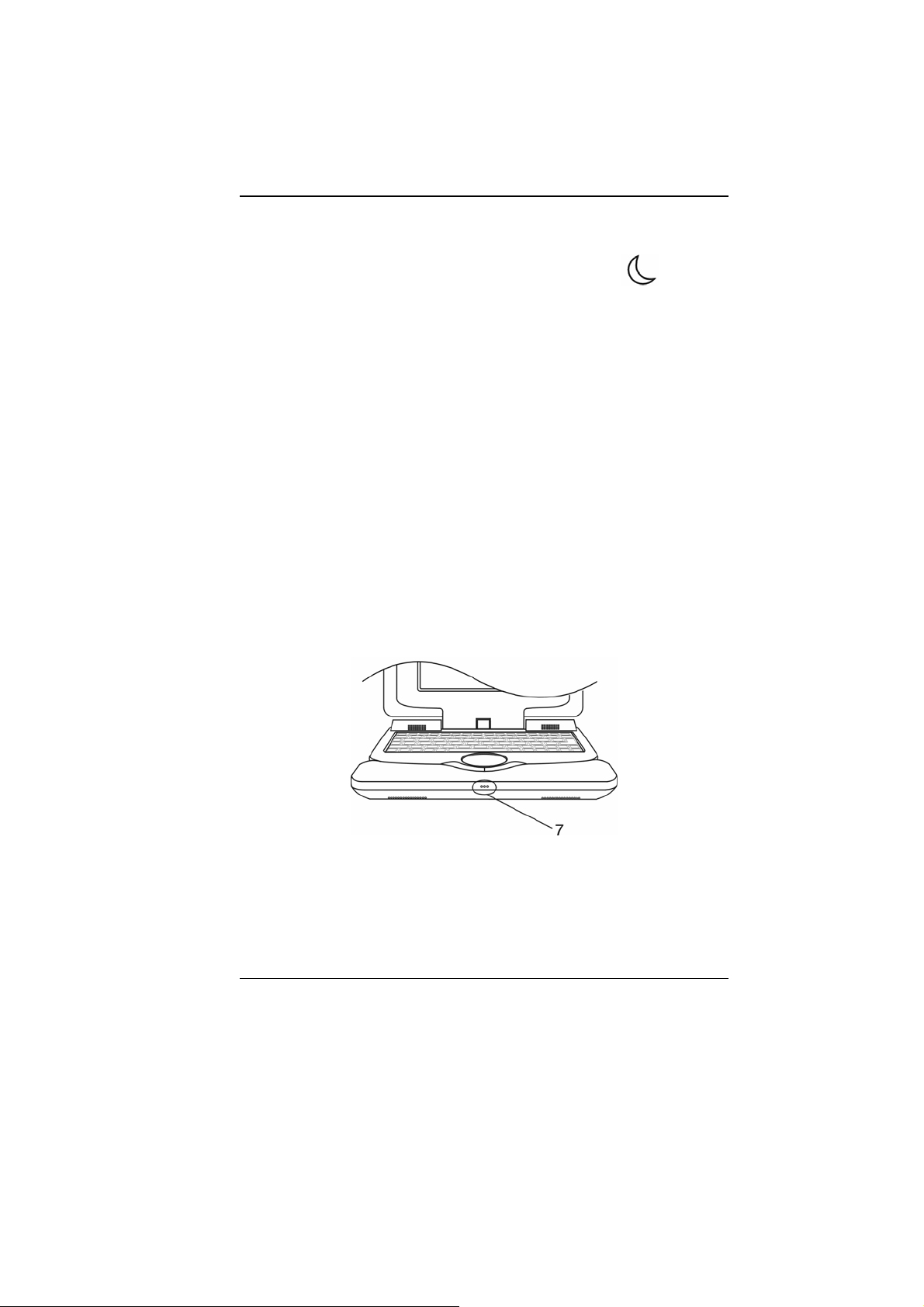
7. Built-in Microphone
The built-in microphone records sound.
LED
12
Page 19

Side Views
Do not place any heavy objects
on the top of notebook. This may damage the display.
1. Ethernet / LAN Port
The port connects to a network hub via the RJ-45 cable
and also conforms to 10/100Base-TX transmission
protocol.
2. USB2.0 Port (x2)
The Universal Serial Bus (USB2.0-compliant) port allows
you to connect a wide variety of devices to your computer
at a rate of up to 480 Mbps. This port conforms to the
latest USB2.0 plug-and-play standards.
3. Microphone Jack
The microphone jack (3.5 mm diameter) is where you
connect a microphone.
4. Stereo Headphone Jack
The stereo headphone jack (3.5 mm diameter) is where
you connect the headphones or external speakers.
5. Ventilation Grill
The fan grill is where air is exchanged to dissipate the
internal heat. Do not completely block this airway.
13
Page 20

6. Power Jack (DC-in)
The DC-out jack of the AC Adapter connects here and
powers the computer.
7. 2-in-1 Card Reader
The 2-in-1 Card Reader supports SD Card and MMC
Card. You need to remove the outer jacket to access the
card reader slot on the rear side of the computer.
Flip open the jacket and the card reader slot is seen.
AC Adapter
14
Page 21

1. DC-out Connector
The DC-out connector docks to the power jack (DC-in) on
the computer.
2. Adapter
The adapter converts alternating current into constant DC
voltage for the computer.
3. AC Plug
The AC Plug plugs to the AC wall outlet.
LED Status Indicator
The LED Status Indicator displays the operating status of your
notebook. When a certain function is enabled, an LED will light up.
The following section describes the indication.
System & Power Status Indicators
LED Graphic
Symbol
Indication
Green light indicates the system is ON.
Green light indicates the notebook is in the suspend
mode.
Orange light indicates the battery is being charged.
Blinking Orange light indicates the battery power is low.
Green light indicates the battery is Full and the AC
Adapter is plugged in.
No light indicates that the battery pack is removed.
When the AC Adapter is plugged in, the alternating
Green-and-Orange LED light indicates that the system
stops charging the battery because the battery-pack’s
temperature is too high.
Green light indicates the NAND Flash or the hard drive
(optional) is being accessed.
Green light indicates the cap-lock is activated.
Green light indicates the numeric keypad is activated.
Green light indicates the WLAN module is active.
15
Page 22

Keyboard Features
Function Keys (Quick Keys)
The function keys allow you to quickly access certain controls,
such as screen brightness, audio volume, suspend mode, etc.
Press and hold the Fn key and then press the various function key
to activate the following controls.
Graphic
Symbol
Action System Control
Fn + F1 Turns the WLAN module off or on.
When the Wireless LAN function is enabled, the
LED status indicator shows green light.
Fn + F2 Enables or Disables the Card Reader function.
Fn + F4 Enters the Suspend Mode.
When the system is in Suspend Mode, the
LED status indicator shows green light.
Fn + F5 Decreases Display Brightness.
Fn + F6 Increases Display Brightness.
Fn + F9 Turns Speaker Volume down.
Fn + F10 Turns Speaker Volume up.
Fn+Num Lk Enables the embedded keypad to work in
numeric mode. The keys act like numeric
keypads in a calculator. Use this mode when
you need to do a lot of numeric data entry. An
alternative would be to connect an external
numeric keypad.
Caps Lock Turns the character capitalization on or off.
Fn+Scr Lk
16
When the numeric keypad is enabled, the
LED status indicator shows green light.
When the cap lock is enabled, the LED
status indicator shows green light.
Press the Fn+Scroll Lock key and then press ↑
or ↓to move one line up or down.
Page 23

Windows* Keys
Your keyboard also has two Windows keys:
1. Start Key
This key allows you to pull up the Windows Start Menu at the
bottom of the taskbar.
2. Application Menu Key
This key brings up the popup menu for the application, similar to a
click of the right mouse button.
Embedded Numeric Keypad
Press Fn+Num Lk to enable the embedded numeric keypad. The
numbers are printed in the upper right corner of a key, in a color
different from the alphabets. This key pad is complete with
arithmetic operators (+, -, * , /).
Press Fn+Num Lk to revert to normal character keys.
Touch Pad
The built-in touch pad, which is a PS/2-compatible pointing device,
senses movement on its surface. As you move your fingertip on
the surface of the pad, the cursor responds accordingly.
The following items teach you how to use the touch pad:
1. Move your finger across the touch pad to move the cursor.
2. Press buttons to select or execute functions.
These two buttons are similar to the left and right buttons on a
mouse. Tapping on the touch pad twice produces is similar to
clicking the left button of a mouse.
Function Left Button Right
Button
Execution Click twice
quickly
Selection Click once Tap once
Drag Click and
hold to drag
the cursor
Tap twice (at the same speed
Tap twice quickly and on the
Equivalent Tapping Action
as double-clicking
the mouse button)
second tap hold finger to the
touch pad to drag the cursor
17
Page 24

Access Context
Menu
Move One Page
Up or Down
Click once
Tips on Using the Touch Pad:
1. The double-click speed is timed. If you double-click too
slowly, your notebook responds as if you single-clicked
twice.
2. Keep your fingers dry and clean when using the touch
pad. Also keep the surface of touch pad clean and dry to
prolong its life.
3. The touch pad is sensitive to finger movements. Hence,
the lighter the touch, the better the response. Heavy touch
does not produce better response.
Graphic Subsystem
Your computer uses a high performance 7 inch active matrix TFT
panel with high resolution and multi-million colors for comfortable
viewing. The Intel Express integrated video graphics accelerator,
which is Microsoft DirectX 9 compatible, performs graphic
rendering at a lighting-fast speed.
About the Display Switcher Utility
A classmate PC has unique utility software called the Display
Switcher that allows the user to choose between the different
display modes quickly and easily.
The native display resolution for a classmate PC is 800x480, which
is 16:9 in aspect ratio. The 16:9 LCD panel may cause some
display problems because most applications are written for the
typical 4:3 display-panel. The Display Switcher utility allows you to
solve this problem.
Please refer to the Display Switcher
Utility user’s manual for detailed information.
Adjusting the Display Brightness
The notebook uses special key combinations, called hot keys, to
control brightness.
• Press Fn + F6 to increase the brightness.
• Press Fn + F5 to decrease the brightness.
18
Page 25

To maximize your battery operating time,
set the brightness to the lowest comfortable setting, so that
the internal backlight uses less power.
Extending the Life of the TFT Display Device
Observe the following guidelines to maximize the life of the
backlight in the display.
1. Set the brightness to the lowest comfortable setting
(Fn+F5).
2. Do not disable the suspend time-outs.
3. If you are using AC power, change to suspend mode
when not in use.
Opening and Closing the Display Panel
To open the display, simply lift up the lid and then tilt it to a
comfortable viewing position.
To close the display cover, fold it down gently.
To avoid damaging the display,
do not slam it when closing. Do not place any object on top of
the computer when the display is closed.
Audio Subsystem
Your computer’s audio subsystem is Sound Blaster Pro-compatible.
Adjusting the Volume Manually
To increase the volume, press Fn + F10.
To decrease the volume, press Fn + F9.
Adjusting the Audio Volume in Operating System
1. Click the speaker symbol in the task tray in operating
system.
2. Drag the volume control bar up or down to adjust the
volume.
3. To temporarily silence the speaker without changing the
volume setting, click Mute.
Voice Recording
A built-in microphone allows you to record sound. You will need to
use audio processing software to enable the built-in microphone.
19
Page 26

For example, you may use Microsoft Sound Recorder.
Ethernet
Your computer is equipped with a 10/100Base-TX Fast Ethernet
network adapter. Connect the active LAN cable to the RJ-45 LAN
port located on the left side of the computer. This allows you to
access and transmit data in the local area network.
Connecting to the Network
Use Unshielded Twisted Pair (UTP) Ethernet cable only.
1. Insert one end of the UTP cable into the network
connector until the connector snaps securely into the
receptacle.
2. Either connect the other end of the cable to an RJ-45 jack
wall outlet or to an RJ-45 port on a UTP concentrator or
hub in the network.
Cabling Restriction for Networks
The following restrictions should be observed for 10/100BASE-TX
networks:
• The maximum cable run length is 100 meters (m) (328 feet [ft]).
Consult Operating System manual for
the software installation, configuration, and operation of the
network.
20
Page 27

33.. BBAATTTTEERRYY PPOOWWEERR && PPOOWWEERR
MMAANNAAGGEEMMEENNTT
In this chapter, you will learn how to operate your notebook on
battery power and learn about the system’s power saving features.
TFT display, central processor, hard disk drive (optional) are the
major hardware subsystems that consume the most power. Power
management deals how these key components should behave to
conserve power. For example, you can have the system turn off its
display after two minutes of inactivity to save power. Efficient
power management can help you for work longer sessions before
having to recharge the battery.
The Battery Pack
Lithium-Ion Battery
Your notebook uses a six-cell Lithium-Ion battery pack that
provides power when you don’t have access to an AC outlet.
You must charge the battery pack for at
least six hours before using it for the first time.
In the Standby Suspend mode, a fully charged battery loses
its power in roughly 1/2 day or less. When not being used, the
battery’s power will deplete in one to two months.
The battery pack in this system is not removable by the user.
Battery Low-Power Warning
1. Low Battery Warning
Low battery condition occurs when battery power is reduced to 6
percent. The red battery status LED indicator blinks and the
system beeps once every 16 seconds or so.
2. Very Low Battery Warning
Very Low battery condition occurs at 3 percent power remaining.
The red battery status LED indicator blinks and the system beeps
at 4-second interval.
21
Page 28

When the notebook warns you of its low battery condition, you will
have about three to five minutes to save your current work.
Do not expose battery packs to
temperatures below 0 degree Celsius (32 degree F) or above
60 degree C (140 degree F). This may adversely affect the
battery pack.
Charging the Battery and Charging Time
To charge the battery, plug the AC adapter into the notebook and
an electrical outlet.
For a totally discharged battery, it will take approximately two hours
to charge to 90% capacity, and approximately three hours to 100%
capacity while classmate PC is powered off. It will take about 5 hrs
to charge the battery to 100% capacity while classmate PC is
powered on.
When the battery is fully charged, the battery charge indicator
becomes green.
If system runs at heavy loads or in a high
temperature environment, the battery may not be fully
charged. You need to continue to charge it with the AC
adapter plugged in until the charging LED turns green.
System will not charge battery when
temperature exceeds 45°C.
Checking the Battery Level
You can check the remaining battery power in Operating System
battery status indicator.
Prolonging the Battery’s Life and Usage Cycles
There are ways you can prolong the use of battery.
• Use the AC adapter wherever AC wall outlet is available. This
will ensure uninterrupted computing.
• Store the battery pack in room temperature. Higher
temperature tends to deplete the battery’s power faster.
• Make good use of the power management function. Save To
Disk (Hibernate) saves the most energy by storing current
system contents in a hard disk space reserved for this function.
22
Page 29

• The life expectancy of the battery is approximately 300
recharges.
• See the notices section in the beginning of the user manual on
how to care for the battery pack.
• Use Function+F5 key to decrease the brightness of the screen.
To achieve optimal battery performance, you may need to do
a battery calibration at a 3-month interval. To do this:
• Fully charge the battery.
• Then discharge the battery by entering the BIOS setup screen.
(Press DEL key as soon as you turn on the computer. And let it
remain at the setup screen until the battery runs out.
• Fully charge the battery again.
Using Power Options
Operating System Power Management provides basic power
saving features. In the power configuration dialogue box, you may
enter time-out values for display and hard disk drive. Operating
System power manager saves power by turning off hard drive after
1 minute of inactivity, for example.
Also consult Operating System user
guide for more information on how to use Operating System
power management functions. Actual dialogue box shown
above may appear slightly different.
Suspend Mode
Standby Suspend
The system automatically enters this mode after a period of
inactivity, which is set in the Power Schemes dialog box. In
Standby mode, hardware devices, such as display panel and hard
disk, are turned off to conserve energy.
Hibernate Suspend
In this mode, all system data are saved in the hard disk before
powering down. When this mode is activated, all system state and
contents are saved to the hard disk drive after a period of inactivity
defined by the user.
No power or very little power is drawn from the battery module
under this mode.
23
Page 30

However, depending on how much RAM that has been installed on
your computer, the amount of time the system requires to restore
all its previous contents can range from five to 20 seconds.
Power Button Action
A classmate PC’s power button can be set to turn off the system or
activate the suspend mode.
24
Page 31

44.. BBIIOOSS SSEETTUUPP AANNDD SSEECCUURRIITTYY
FFEEAATTUURREE
The Setup Utility is a hardware configuration program built into
your computer’s BIOS (Basic Input/Output System). It runs and
maintains a variety of hardware functions. It is menu-driven
software, which allows you to easily configure and change the
settings.
The BIOS contains manufacturer’s default settings for the
computer’s standard operations. However, there are occasions
when you may be required to modify the default settings in the
BIOS.
The BIOS allows you to set up passwords to limit access to users.
This is an important feature because a great deal of vital
information is carried within the computer nowadays. Unauthorized
access can be prevented. Later in this chapter, you will learn how
to use this security feature.
The BIOS Setup Utility you see on your
notebook may appear slightly different than what is shown in
this manual, because your notebook may have newer BIOS
version installed.
Entering the BIOS Setup Screen
First turn on the power. When the BIOS performs the POST
(Power-On Self Test), press Del key quickly to activate the AMI
BIOS Setup Utility.
You may need to press Del key fairly
quickly. Once the system begins to load Operating System,
you may have to retry by cycle-power on again.
Leaving the BIOS Setup Screen
When you have finished modifying the BIOS settings, exit the
BIOS. It takes a few seconds to record changes in the CMOS.
25
Page 32

BIOS Action Keys
Function Key Command Description
Leaves a sub-menu to return to the
ESC Exit
Enter Go to Sub Screen Shows the Sub Menu.
F1 General Help Shows the Help Screen .
F9 Setup Defaults Load default values.
F10 Save and Exit
<Tab> Select a field Selects the next field.
↑ Select an item Selects the next upper item.
↓ Select an item Selects the next lower item.
- Lower value Selects the next value within a field.
+ Higher value Selects the next value within a field.
previous menu OR exits the BIOS setup
while saving changes.
Saves changes and reboots the
computer.
Modifying the BIOS Settings
The AMI BIOS setup main menu is subdivided into sub-menus.
Each menu item is described in this section.
26
Page 33

Main Setup
Under this menu, you may view BIOS Version and system memory
capacity and also change system time and date.
BIOS SETUP UTILITY
Main Advanced Security Boot Exit
BIOS Information
BIOS Version: x.xx
EC Version: x.xx
System Memory
Size: 248MB
System Time: [12:12:00]
System Date: [Thu
10/26/2006]
Language: [English]
Use [+] or [-] to configure
system Time.
←→ Select Screen
↑↓ Select Item
-/+ Change Field
Tab Select Field
F1 General Help
F10 Save and Exit
ESC Exit
(C) Copyright 1985-2004, American Megatrends, Inc.
Due to various configurations on this
model, your system may show different information.
• System Time: Type in the current time, in HH:MM:SS format.
• System Date: Type in the current date, in MM/DD/YY format.
• Language: See Below.
Item Selections /
Sub-menu
Language Spanish
Portuguese
English
This is the language selection for Intel’s
TPM function (the new hardware-based
security protocol that authenticates the
notebook PC.)
Description
27
Page 34

Advanced Setup
Under this menu, you may view CPU information, configure HDD
(optional), and enable/disable wireless LAN and LAN port.
BIOS SETUP UTILITY
Main Advanced Security Boot Exit
Advance Settings
WARNING: Setting wrong values in below
sections may cause system to malfunction.
► CPU Configuration
► IDE Configuration
► Communication
(C) Copyright 1985-2004, American Megatrends, Inc.
Configure CPU.
←→ Select Screen
↑↓ Select Item
Enter Go to Sub Screen
F1 General Help
F10 Save and Exit
ESC Exit
Communication: See Below.
Item Selections /
Sub-menu
Wireless LAN Enable/Disable Enable or disable the WLAN Module.
Card Reader Enable/Disable Enable or disable the Card Reader
function.
Description
28
Page 35

Security Setup
BIOS SETUP UTILITY
Main Advanced Security Boot Exit
Security Settings
Supervisor Password: Not Installed
User Password: Not Installed
Change Supervisor Password
Change User Password
(C) Copyright 1985-2004, American Megatrends, Inc.
Install or change the
password.
←→ Select Screen
↑↓ Select Item
Enter Change
F1 General Help
F10 Save and Exit
ESC Exit
• Supervisor Password: Install or Change the Password.
• User Password: Install or Change the Password.
Using Password Protection
Two Levels of Password Protection are available. The BIOS
provides both a Supervisor and a User password. If you try to
activate both passwords, the Supervisor password must be set first.
The passwords activate two different levels of protection:
1. System always asks for password every time it is powered on.
2. System asks for password only when you attempt to enter
BIOS utility.
The passwords are encrypted and stored in NVRAM. Make sure
you write them down or memorize them. If you loose the
passwords, the computer may need to be sent back to the factory
or to an authorized service dealer to reset the passwords.
29
Page 36

Boot Setup
BIOS SETUP UTILITY
Main Advanced Security Boot Exit
Boot Settings
► Boot Settings Configuration
► Boot Device Priority
► Hard Disk Drives
► Removable Drives
(C) Copyright 1985-2004, American Megatrends, Inc.
Install or change the
password.
←→ Select Screen
↑↓ Select Item
Enter Change
F1 General Help
F10 Save and Exit
ESC Exit
• Boot Settings Configuration: See Below.
Item Selections /
Sub-menu
Quick Boot Disabled
Enabled
Quiet Boot Disabled
Enabled
PS/2 Mouse
Support
Disabled
Enabled
Auto
30
Description
[Enabled]: The system skips certain tests
while booting. This shortens the boot-up
time.
[Disabled]: The system performs full tests
while booting.
When Enabled, the system will display
OEM logo instead of the POST messages.
When Disabled, the system will display
POST messages (i.e. devices information.)
Disable or Enable the built-in touchpad.
Page 37

• Boot Device Priority: See Below.
Item Selections /
Sub-menu
First Boot
Device
Second
Boot Device
Third Boot
Device
USB: M-Sys
uDiskOnChip
USB: Generic
STORAGE
Network: Realtek
Boot Agent
Set the type of device for the first drive
BIOS attempts to boot from. If Realtek
Boot Agent is selected, system will attempt
to load boot sector from the Ethernet port.
Set the type of device for the second drive
BIOS attempts to boot from.
Description
M-System uDiskOnChip is the system’s
built-in flash storage, where programs and data are stored.
The Realtek Boot Agent allows you to boot from the Network.
When the BIOS performs POST, you may also press F11 Key
to enable the Boot Device selection menu. You may choose
“USB: M-Sys uDiskOnChip”, “USB: Generic Storage Device”,
or “Network: Realtek Boot Agent” as the first storage device
to boot from. If you have already connected a USB Floppy
Disk Drive before powering up, it will appear as a USB FDC in
the Boot Device selection menu.
31
Page 38

Exit Setup
BIOS SETUP UTILITY
Main Advanced Security Boot Exit
Exit Options
Save Changes & Exit
Discard Changes & Exit
Discard Changes
Load Optimal Defaults
(C) Copyright 1985-2004, American Megatrends, Inc.
Exit system setup after saving
the changes.
F10 key can be used for this
operation.
←→ Select Screen
↑↓ Select Item
Enter Go to the Sub Screen
F1 General Help
F10 Save and Exit
ESC Exit
• Save Changes and Exit: After you have completed the BIOS
settings, select this item to save all settings, exit BIOS Setup
utility, and reboot. New system settings will take effect on next
power-up. F10 key can be used for this operation.
• Discard Changes and Exit: Discards changes done so far to
any of the setup questions and exit.
• Discard Changes: Discards changes done so far to any of the
setup questions.
• Load Optimal Defaults: Load Optimal Default value for all the
setup questions. F9 key can be used for this operation.
32
Page 39

55.. UUPPGGRRAADDIINNGG YYOOUUR
CCOOMMPPUUTTEERR
This upgrade activity should only be performed by an adult.
Upgrading the System Memory Module
Many applications will generally run faster when the computer’s
dynamic memory capacity is increased. The computer has a DDR2
memory socket, which is located underneath the keyboard. You
can increase the amount of memory by replacing the existing one
with a dual inline memory module (commonly known as SO-DIMM)
of a higher capacity. The SO-DIMM can be 256MB, 512MB, or
1024MB in capacity. The SO-DIMM is of type DDR2 SDRAM, has
200 pins and runs on 1.8V.
Memory upgrade is a delicate
process. Please observe the following instructions carefully
or have a qualified technician install it for you. Damages due
to mishandling of this procedure are NOT covered by the
manufacturer’s warranty. Changing memory while your
computer is in suspend or power-saving mode may cause
permanent damage to the hardware. Make sure you turn off
the power and unplug the AC cord before proceeding with a
memory upgrade.
R
You should only use the DIMM module that is approved by the
reseller or the manufacturer; otherwise the system may
become unstable.
To install the DIMM under the keyboard, do the following:
1. Power OFF the notebook. Unplug the AC cord and all
cables/devices attached to the notebook.
2. Place your hand on a large metal object momentarily to
discharge any static electricity. Place the notebook on a
flat surface and fully open the LCD lid.
3. Find the keyboard latches near the bottom edge of the
keyboard. The latch is spring-loaded. It will retract when
pressed and revert back to its original position when
released.
33
Page 40

Use a small blade to press the latch inward. The keyboard
tray should pop up slightly over the latch.
If the keyboard tray does not pop up, try to gently lift it up
slightly above the latch. Repeat this step for the other
keyboard latch.
34
4. Carefully lift up the bottom edge and do not break-loose
the flex-cable that connects to the keyboard. Turn the
keyboard and the metal cover over, and then the DDR
DIMM Socket is revealed.
Page 41

5. To remove an old DIMM from the socket, press out on the
latches located on both edges of the socket at the same
time. The DIMM should pop up to an angle of 30 degree
(see diagram below). Pull the DIMM module out of the
memory socket. Store the DIMM for the future use.
6. Install the new DIMM module into the memory socket.
The DIMM will only fit in one orientation. Insert the DIMM
at an angle of approximately 30 degrees into the empty
memory socket. Then press it firmly so that the contact
edge is driven into the receiving socket.
35
Page 42

7. Pivot the DIMM until the latches on both sides of the
socket snap into place.
Notice the notch on the DIMM. The
notches should fit nicely with the socket.
8. Put the metal cover and the keyboard back to their
original position. Make sure the bottom edge of the
keyboard now resides under the spring-loaded latches.
You may need to use a small pin to push in the latch first,
otherwise the keyboard will not fit in.
Congratulations! You have just completed the memory upgrade.
When you boot up the computer, you should expect to see an
increase in DRAM capacity.
36
Page 43

Your computer has been tested with a
wide range of DIMM on the market. However, not all memory
modules are compatible. Check with your system vendor for a
list of compatible DIMM for your computer.
Upgrading the Mass-Data-Storage Device
To upgrade the mass-data-storage capacity, you can either replace
the existing M-System flash storage module with one that has a
higher capacity, or instead, replace it with the 1.8 inch P-ATA-type
hard disk drive module. You need to obtain the optional upgrade
kits from your dealer, as this type of module is not commonly
available.
Be sure to make a backup copy of all your data before attempting
this operation.
The upgrade is a delicate
process. Please observe the following instructions carefully
or have a qualified technician install it for you. Damages due
to mishandling of this procedure are NOT covered by the
manufacturer’s warranty.
Apply care when handling the hard disk.
• Do not drop or apply any shock.
• Do not press on the cover.
• Do not touch the connector with your fingertips.
• Mishandling of the hard drive can result in permanent loss of
data. Make a backup copy of the content within the drive
before you remove it.
Upgrading the M-System Flash Storage Module
To upgrade the flash storage module, do the following:
1. Follow the first four steps in the previous section,
Upgrading the System Memory Module, to access the
Flash Storage Module.
2. Locate and remove one Screw A.
37
Page 44

3. Gently lift the old module and replace it with the new one.
When you do this, be sure that the flash module
connector is properly seated on the main-board, as the
connector may be attached to the old flash module. The
connector is what links the flash module to the system
board.
38
4. Re-attach Screw A.
5. Put the metal cover and the keyboard back to their
original position. Make sure the bottom edge of the
keyboard now resides under the spring-loaded latches.
You may need to use a small pin to push the latch in first,
before you lower the keyboard.
Page 45

Congratulations! You have just completed the flash module
upgrade. You may need to reformat the new flash storage module
and re-install O/S, drivers, and all the necessary applications.
Installing the Optional Hard Disk Drive Module
To replace the flash storage module with the hard disk drive
module, do the following:
1. Follow the first four steps in the previous section,
Upgrading the System Memory Module, to access the
hard disk drive bay.
2. Locate and remove one Screw A.
39
Page 46

3. Gently lift the old module. Be sure that you remove the
flash connector as well. You need to remove the existing
flash module in order to install the hard disk drive module.
40
4. The HDD module comes with a metal casing and a flex-
cable with HDD connector. Place the HDD module into
the HDD module bay and join together the two HDD
connectors as shown below.
Page 47

5. Put the metal cover and the keyboard back to their
original position. Make sure the bottom edge of the
keyboard now resides under the spring-loaded latches.
You may need to use a small pin to push the latch in first,
before you lower the keyboard.
41
Page 48

Congratulations! You have just completed the hard disk drive
installation. You may need to reformat the new drive and re-install
O/S, drivers, and all the necessary applications.
42
Page 49

66.. TTRROOUUBBLLEE SSHHOOOOTTIINNGG
The trouble shooting activity should only be performed by an adult.
Your computer has been fully tested and complies with the system
specifications before shipping. However, incorrect operations
and/or mishandling may cause problems.
This chapter provides a reference for identifying and correcting
common hardware and software problems that you may encounter.
When you encounter a problem, you should first try to go through
the recommendations in this chapter. Instead of returning the
computer and waiting for repair, you may easily solve the problems
by considering the following scenarios and possible solutions. If
the error continues, contact your reseller for service information.
Before taking further actions, consider the following suggestions:
• Check to see if the problem persists when all the external
devices are removed.
• Check to see if the power cord is properly plugged into the wall
outlet and to the computer.
• Check to see the power indicator of the computer is on.
• Check to see if your keyboard is operational by pressing and
holding any key.
• Check for any incorrect or loose cable connections. Make sure
the latches on the connectors latch securely on to the receptor
end.
• Be sure you have not performed an incorrect setting on the
hardware devices in the BIOS Setup utility. A faulty setting may
cause the system to malfunction. If you are not sure of the
changes you made, try to restore all the settings to factory
defaults.
• Be sure all the device drivers are installed properly. For
example, without the audio driver properly installed, the
speakers and microphone will not work.
• If external devices such as USB camera, scanner or printer do
not function correctly when connected to the system, it is
usually the device’s own problem. Consult the device’s
manufacturer first.
43
Page 50

• Some software programs, which have not gone through
rigorous coding and testing, may cause problems during your
routine use. Consult the software vendor for problem solving.
• Be sure to go to BIOS SETUP and load DEFAULT SETTING
after BIOS re-flash.
Audio Problems
No speaker output
• Software volume control is turned down in Operating System’s
Sound System or is muted. Double-click the speaker icon on
the lower right corner of the taskbar to see if the speaker has
been muted or turned down all the way.
• Most audio problems are software-related. If your computer
worked before, chances are software may have been set
incorrectly.
Sound cannot be recorded
• Double-click the speaker icon on the lower right corner of the
taskbar to see if the microphone has been muted.
1. Click Options and select Properties.
2. Select Recording and click the OK button.
3. After clicking the OK button, the recording volume control
panel will appear.
Hard Disk (Optional) Problems
The hard disk drive does not work or is not recognizable:
• If you had just performed a hard disk upgrade, make sure the
hard drive connector is not loose and the hard disk drive is also
correctly seated. Remove it and reinsert it firmly, and restart
your PC. (Refer to Chapter 5 for details.)
• The new HDD may need to be partitioned and reformatted. O/S
and drivers will need to be re-installed as well.
• Check the hard disk indicator LED. When you access a file, the
LED lamp should light up momentarily.
• The new HDD may be defective or is not compatible.
• If your computer has been subjected to static electricity or
physical shock, you may have damaged the disk drive.
The hard drive is making abnormal whining noises
• You should back up your files as soon as possible.
44
Page 51

• Make sure the source of noise is indeed from the hard drive
and not the fan or other devices.
The hard disk drive has reached its capacity
• Archive files or programs that you had no longer used by
moving them to an alternative storage medium (card reader,
etc.) or uninstall programs that are no longer used.
• Many browsers store files in the hard drive as a cache to speed
up the performance. Check the program’s Online Help for
instructions on decreasing the cache size or on removing
temporary Internet files.
The hard disk takes longer to read a file
• Interrupt requests or problems with other hardware devices
may have occupied the CPU and therefore slows down the
system performance.
Display Problems
The display panel is blank when the system is turned on
• Make sure the computer is not in the Standby or Hibernate
suspend modes. The display is turned off to conserve energy in
these modes.
The screen is difficult to read
• The display resolution should at least be set to at least
800x480 for optimal viewing.
The screen flickers
• It is normal if the display flickers a few times during shutting
down or powering up processes.
Keyboard and Touchpad Problems
The built-in touch pad performs errotically
• Make sure there is no excess perspiration or moisture on your
hand when using the touch pad. Keep the surface of the touch
pad clean and dry.
• Do not rest your palm or wrist on the surface of the touch pad
while typing or using the touch pad.
The built-in keyboard accepts no input
• If you are connecting an external keyboard to the system, the
built-in keyboard may not work.
45
Page 52

• Try restarting the system.
The characters on the screen repeat while I type.
• You may be holding the keys down too long while you’re typing.
• Keep the keyboard clean. Dust and dirt under the keys could
cause them to stick.
Memory Problems
The POST does not show an increased memory capacity
when you have already installed additional memory
• Certain brands of memory module may not be compatible with
your system. You should ask your vendor for a list of
compatible DIMM.
• The memory module may not be installed properly. Go back to
Chapter 4 to review the details of this operation.
• The memory module may be defective.
The O/S issues an insufficient memory error message during
operation
• This is often a software or Operating System-related problem.
A program is draining the memory resources.
• Close the application programs you’re not using and restart the
system.
• You need to install additional memory module. For instructions,
go to Chapter 4 Upgrading Your Computer.
Network Adapter / Ethernet Problems
The Ethernet adapter does not work
• Make sure the physical connections on both ends of the cable
are good.
• The hub or concentrator may not be working properly. Check to
see if other workstations connected to the same hub or
concentrator is working.
The Ethernet adapter does not appear to operate in the
100Mbps transmission mode
• Make sure the hub you are using supports 100Mbps operation.
• Make sure that your RJ-45 cable meets the 100Base-TX
requirements.
46
Page 53

• Make sure the Ethernet cable is connected to the hub socket
that supports 100Base-TX mode. The hub may have both
10Base-TX and 100Base-T sockets.
Performance Problems
The computer becomes hot
• In a 35oC environment, the certain areas of the computer’s
back case are expected to reach 50 degrees.
• Make sure the air vents are not blocked.
• If the fan does not seem to be working at high temperature (50
degrees Celsius and up), contact the service center.
• Certain programs that are processor-intensive may increase
the computer temperature to a degree where the computer
automatically slows down its CPU clock to protect itself from
heat damage.
The program appears stopped or runs very slowly
• Restart the computer.
• This may be normal for Operating System when it is
processing other CPU-intensive programs in the background or
when the system is accessing slow-speed devices such the
floppy disk drive.
• You may be running too many applications. Try to close some
applications or increase system memory for higher
performance.
• The processor may have been overheated due to the system’s
inability to regulate its internal temperature. Make sure the
computer’s ventilation grills are not blocked.
USB2.0 Problems
The USB device does not work
• Make sure the cable is fully connected.
• Make sure you have installed the necessary device drivers.
• Contact the device vendor for additional support.
47
Page 54

48
Page 55

AAppppeennddiixx:: SSppeecciiffiiccaattiioonn
Processor and Core Logic
¾ Intel Celeron M, Ultra Low Voltage version
Core Logic
¾ Intel 915GMS+ICH6-M chipset with graphic, audio, and
USB2.0 controllers integrated
¾ 400MHz Front Side Bus
¾ 400MHz DDR2 interface
System Memory
¾ DDR2 SDRAM 400
¾ 256 / 512MB
¾ One 200-pin DIMM socket
Display
¾ 7-inch 800x480 TFT LCD
VGA
¾ Intel Express Integrated Graphic Engine
¾ Hardware Motion Compensation and IDCT Supported
for MPEG1/2 Playback
¾ DirectX compatible
Audio
¾ Intel ICH6-M integrated audio controller
¾ VIA VT1618
¾ DirectSound 3D, EAX 1.0 & 2.0 compatible
¾ A3D, I3DL2 compatible
¾ AC97 V2.3 compatible
¾ Two Stereo Speakers
Wireless LAN
¾ Billionton GUSBWLRGM Wireless Card
¾ USB Interface, IEEE802.11B&G
LAN / Ethernet
¾ Realtak RTL8100CL Ethernet function for 10/100Base-
TX network standards
49
Page 56

PnP Function
¾ Plug and Play compatible
Flow Control
¾ Automatic Jam and auto-negotiation for flow control
¾ Auto Negotiation and Parallel detection for automatic
Speed Selection
¾ Speed selection (IEEE 802.3u)
¾ High performance 32-bit PCI bus master architecture
with integrated DMA controller for low CPU and bus
utilization
Other Features
¾ Remote Wake-up Scheme supported
¾ Hot Insertion supported
Mass Data Storage
¾ NAND-type, 1GB / 2GB
¾ P-ATA 1.8-inch format hard disk drive
Keyboard & Touch pad
¾ 77-key QWERTY keyboard
¾ Built-in Touch Pad
Multiple Card Reader
¾ Multimedia Card (MMC) and Secure Digital Card (SD)
Ports and Connectors
¾ One Microphone jack
¾ One Headphone jack
¾ Two USB2.0-compliant connectors
¾ One standard network Ethernet connector (RJ-45)
¾ One DC-in connector
¾ One 2-in-1 Card Reader Slot
Battery Pack / AC Adapter
¾ Li-ion 4-Cell pack, 14.8 V x 2000 mAH or
¾ Li-ion 4-Cell pack, 14.4 V x 2200 mAH or
¾ Li-ion 6-Cell pack, 11.1V x 4000 mAH or
¾ Li-ion 6-Cell pack, 10.8V x 4400 mAH or
¾ Li-ion 6-Cell pack, 11.1V x 4400 mAH
¾ Low battery state with low battery warning beep
50
Page 57

Adapter
¾ Autosensing AC-in 100~240V, DC-out 20V, 65W or 40W
BIOS
¾ AMI PnP BIOS
¾ Power On Self Test
¾ DRAM auto-detection, auto-sizing
¾ L2 Cache auto-detection
¾ Hard disk type auto-detection
¾ ACPI 2.0 (Advanced Configuration Power Interface)
¾ Two Level Password Protections
¾ 32bit access, Ultra DMA, PIO5 Mode support
¾ Multi-boot capability
Operating System
¾ Compatible with Microsoft Windows XP Pro
¾ Linux
Physical Specification
¾ 244 (W) x 191.2 (D) x 35.4 (H) mm
¾ 1.38KG / 3.04lbs (with 4-cell battery pack)
Temperature
¾ Operating Humidity: 20 to 80 percent RH (5°C to 40°C or
41°F to 104°F)
¾ Storage Temperature: -15°C to 60°C (-5°F to 140°F)
51
 Loading...