

Page 1

Page 2

Page 3

Preface
Copyright
This publication, including all photographs, illustrations and software, is protected under
international copyright laws, with all rights reserved. Neither this manual, nor any of the
material contained herein, may be reproduced without written consent of the author.
Version 1.0
Disclaimer
The information in this document is subject to change without notice. The manufacturer
makes no representations or warranties with respect to the contents hereof and specifically
disclaims any implied warranties of merchantability or fitness for any particular purpose.
The manufacturer reserves the right to revise this publication and to make changes from
time to time in the content hereof without obligation of the manufacturer to notify any
person of such revision or changes.
Trademark Recognition
Microsoft, MS-DOS and Windows are registered trademarks of Microsoft Corp.
MMX, Pentium, Pentium-II, Pentium-III, Celeron are registered trademarks of Intel Corporation.
Other product names used in this manual are the properties of their respective owners and
are acknowledged.
Federal Communications Commission (FCC)
This equipment has been tested and found to comply with the limits for a Class B digital
device, pursuant to Part 15 of the FCC Rules. These limits are designed to provide reasonable protection against harmful interference in a residential installation. This equipment
generates, uses, and can radiate radio frequency energy and, if not installed and used in
accordance with the instructions, may cause harmful interference to radio communications.
However, there is no guarantee that interference will not occur in a particular installation.
If this equipment does cause harmful interference to radio or television reception, which
can be determined by turning the equipment off and on, the user is encouraged to try to
correct the interference by one or more of the following measures:
• Reorient or relocate the receiving antenna.
• Increase the separation between the equipment and the receiver.
• Connect the equipment onto an outlet on a circuit different from that to which
the receiver is connected.
• Consult the dealer or an experienced radio/TV technician for help.
Shielded interconnect cables and a shielded AC power cable must be employed with this
equipment to ensure compliance with the pertinent RF emission limits governing this
device. Changes or modifications not expressly approved by the system’s manufacturer
could void the user’s authority to operate the equipment.
Preface
Page 4

ii
Declaration of Conformity
This device complies with part 15 of the FCC rules. Operation is subject to the following
conditions:
• This device may not cause harmful interference, and
• This device must accept any interference received, including interference that
may cause undesired operation.
Canadian Department of Communications
This class B digital apparatus meets all requirements of the Canadian Interference-causing
Equipment Regulations.
Cet appareil numérique de la classe B respecte toutes les exigences du Réglement sur le
matériel brouilieur du Canada.
About the Manual
The manual consists of the following:
Chapter 1
Introducing the Motherboard
Chapter 2
Installing the Motherboard
Chapter 3
Using BIOS
Chapter 4
Using the Motherboard Software
Describes features of the motherboard.
Go to
Describes installation of motherboard
components.
Go to
Provides information on using the BIOS
Setup Utility.
Go to
Describes the motherboard software
Go to
H
H
H
H
page 1
page 7
page 23
page 47
Preface
Page 5

TT
ABLE OF CONTENTSABLE OF CONTENTS
T
ABLE OF CONTENTS
TT
ABLE OF CONTENTSABLE OF CONTENTS
Preface i
iii
Chapter 1
Introducing the Motherboard 1
Introduction................................................................................................1
Features.......................................................................................................2
Motherboard Components.......................................................................4
1
Chapter 2
Installing the Motherboard 7
Safety Precautions......................................................................................7
Choosing a Computer Case.......................................................................7
Installing the Motherboard in a Case......................................................7
Checking Jumper Settings.........................................................................8
Setting Jumpers..............................................................................8
Checking Jumper Settings..............................................................9
Jumper Settings..............................................................................9
Connecting Case Components...............................................................10
Front Panel Header.....................................................................11
Installing Hardware...................................................................................12
Installing Memory Modules.........................................................12
Installing a Hard Disk Drive/CD-ROM/SATA Hard Drive........15
Installing Add-on Cards..............................................................17
Connecting Optional Devices......................................................19
Connecting I/O Devices..........................................................................21
7 7
7
7 7
Chapter 3
Using BIOS 23
About the Setup Utility............................................................................23
The Standard Configuration........................................................23
Entering the Setup Utility..............................................................23
Updating the BIOS.......................................................................25
Using BIOS................................................................................................25
Standard CMOS Features...........................................................26
Advanced BIOS Features.............................................................28
23 23
23
23 23
Page 6

iv
Advanced Chipset Features.........................................................31
Integrated Peripherals.................................................................34
Power Management Setup...........................................................37
PNP/PCI Configurations.............................................................41
PC Health Status..........................................................................42
Frequency/Voltage Control..........................................................43
Load Fail-Safe Defaults................................................................44
Load Optimized Defaults.............................................................44
Set Supervisor/User Password....................................................44
Save & Exit Setup Option.............................................................45
Exit Without Saving......................................................................45
Chapter 4
47 47
47
47 47
Using the Motherboard Software 47
About the Software CD-ROM................................................................47
Auto-installing under Windows 98/ME/2000/XP................................47
Running Setup..............................................................................48
Manual Installation..................................................................................50
Utility Software Reference.......................................................................50
Page 7

Chapter 1
Introducing the Motherboard
Introduction
Thank you for choosing C7VCM2 motherboard of great performance and with enhanced
function. This motherboard has onboard C7 processor with a Mini-ITX form factor of 170
x 170 mm.
The motherboard integrates the VIA CN700 Northbridges and VT8237R Plus Southbridge.
The Northbridge supports a Front Side Bus (FSB) frequency of 400 MHz. The memory
controller supports DDR2 memory DIMM frequencies of 533/400. It supports one DDR2
Socket with up to maximum memory of 1 GB.
The VT8237R Plus Southbridge on this motherboard supports one PCI slot which is PCI 2.2
compliant. It implements eight USB ports with data transfers up to 480 Mb/s. Two onboard
IDE connectors support four IDE devices in Ultra ATA 133/100/66/33 mode. The southbridge
complies with Serial ATA Specification Revision 1.0 with transfer rate up to 1.5 Gb/s per
channel.
There is an advanced full set of I/O ports in the rear panel, including PS/2 ports for mouse
and keyboard, one serial ports, one parallel port, one VGA port, one optional LAN port,
four back-panel USB2.0 ports, and two audio jacks for microphone and line-out.
1
Introducing the Motherboard
Page 8

2
Features
Processor
This motherboard uses onboard C7 processor that carries the following features:
• Accommodates VIA C7 processor
• Supports a system bus (FSB) of 400 MHz
Chipset
The CN700 Northbridge (NB) and VT8237R Plus Southbridge (SB) chipsets are based on
an innovative and scalable architecture with proven reliability and performance.
CN700(NB)
VT8237R
Plus(SB)
Memory
• Supports 400 MHz FSB VIA C7 Processor
• Supports Host dynamic bus inversion (DBI)
• Supports AGP v3.5 compliant 8x/4x transfer modes with Fast
write
• Supports Advanced 64-bit SDRAM controller supportingDDR2
and DDR400/333/226 SDRAM
• Supports Integrated UniChrome Pro 3D/2D Graphics & Video
Controller
• Compliant with UltraDMA-133/100/66/33 Master Mode EIDE Controller supporting four Enhanced IDE devices
• Supports eight USB ports with data transfers up to 480 Mb/s
• Supports AC’97 2.3 specification
• Compliant with Serial ATA Specification Revision1.0
• Supports DDR2 533/400 memory bus
• Supports one Un-Buffered DIMM
• Maximum installed memory is 1 GB
Audio
• Compliant with the AC’97 v2.3 CODEC
• Supports 6-channel audio CODEC designed for PC multimedia systems
• Provides three analog line-level stereo inputs with 5-bit volume control:
LINE_IN, CD, AUX
• Meets Microsoft WHQL/WLP 2.0 audio requirements
Onboard LAN
The onboard LAN provides the following features:
• Supports 10/100 Mb/s N-Way Auto negotiation operation
• Half/Full duplex capability
• Supports Wake-On-LAN (WOL) function and remote wake-up
Onboard Giga LAN (Optional)
The onboard Giga LAN provides the following features:
• Integrated 10/100/1000 transceiver
• Supports PCI v2.3, 32-bit, 33/66MHz
• Supports fully with IEEE802.3, IEEE802.3u and IEEE802.3ab
Introducing the Motherboard
Page 9

Expansion Options
The motherboard comes with the following expansion options:
• One 32-bit PCI slot
• Two IDE connectors which support four IDE devices
• Two 7-pin SATA connectors
The motherboard supports Ultra DMA bus mastering with transfer rates of 133/100/66
33MB/s.
Integrated I/O
The motherboard has a full set of I/O ports and connectors:
• Two PS/2 ports for mouse and keyboard
• One serial port
• One parallel port
• One VGA port
• Four back-panle USB2.0 ports
• One LAN port (optional)
• Audio jacks for microphone and line-out
BIOS Firmware
This motherboard uses Award BIOS that enables users to configure many system
features including the following:
• Power management
• CPU parameters
• CPU and memory timing
The firmware can also be used to set parameters for different processor clock speeds.
3
Some hardware specifications and software items are subject to change
without prior notice.
Introducing the Motherboard
Page 10
4
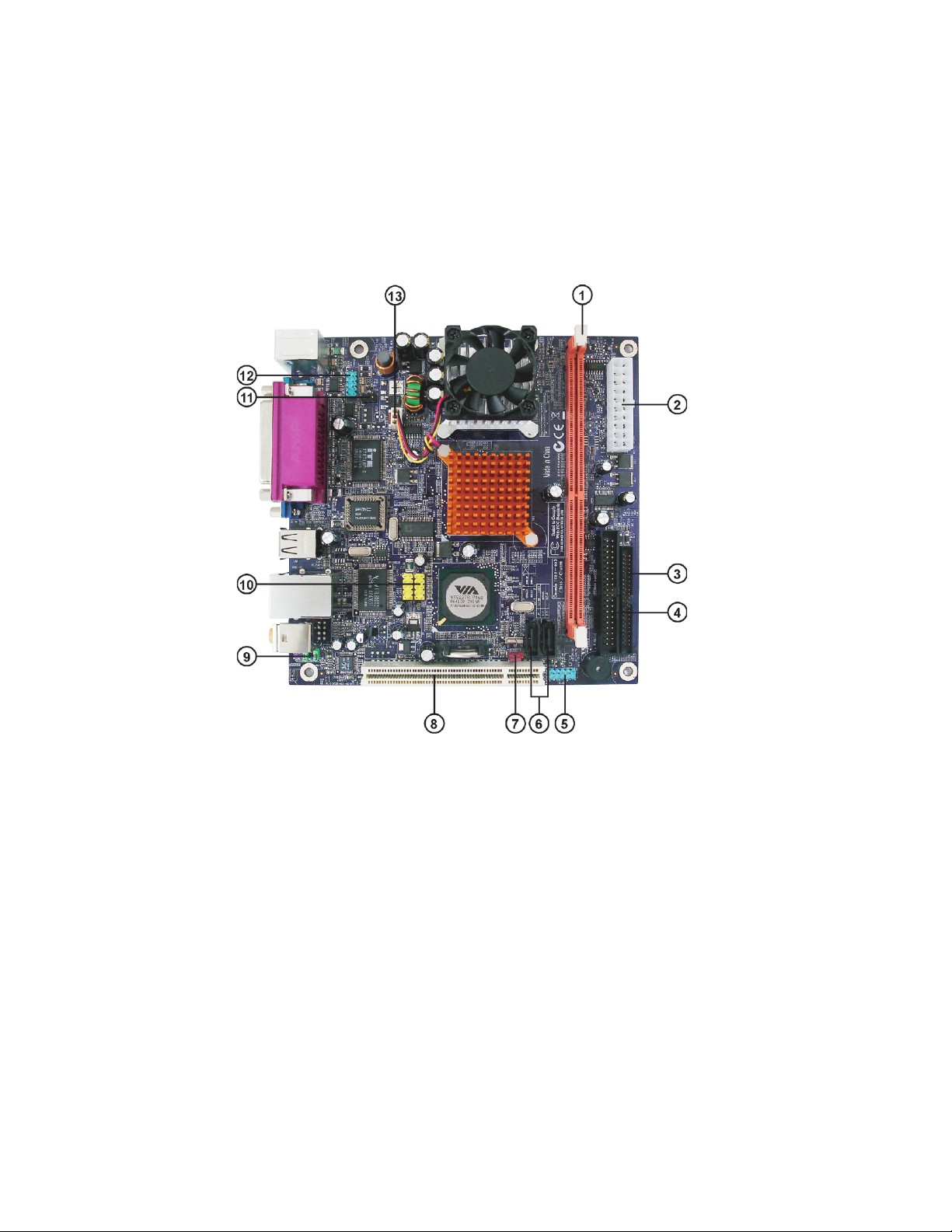
Motherboard Components
Introducing the Motherboard
Page 11

Table of Motherboard Components
LABEL COMPONENTS
1. DDRII1
2. ATX_POWER2
3. IDE2
4. IDE1
5. PANEL1
6. SATA1~2
7. CLR_CMOS1
8. PCI1
9. AUDIO1
10. F_USB1~2
11. IR1
12. COM2
13. CPUFAN1
This concludes Chapter 1. The next chapter explains how to install the motherboard.
240-pin DDR2 SDRAM slot
Standard 20-pin ATX power connector
Secondary IDE connector
Primary IDE connector
Front Panel switch/LED header
Serial ATA connectors
Clear CMOS jumper
32-bit add-on card slot
Front panel Audio header
Front Panel USB headers
Infrared header
Onboard Serial port header
CPU cooling fan connector
5
Introducing the Motherboard
Page 12

6
Memo
Introducing the Motherboard
Page 13

Chapter 2
Installing the Motherboard
Safety Precautions
• Follow these safety precautions when installing the motherboard
• Wear a grounding strap attached to a grounded device to avoid damage from
static electricity
• Discharge static electricity by touching the metal case of a safely grounded
object before working on the motherboard
• Leave components in the static-proof bags they came in
• Hold all circuit boards by the edges. Do not bend circuit boards
Choosing a Computer Case
There are many types of computer cases on the market. The motherboard complies with
the specifications for the Mini-ITX system case. First, some features on the motherboard
are implemented by cabling connectors on the motherboard to indicators and switches on
the system case. Make sure that your case supports all the features required. Secondly, this
motherboard supports one or two floppy diskette drives and four enhanced IDE drives.
Make sure that your case has sufficient power and space for all drives that you intend to
install.
Most cases have a choice of I/O templates in the rear panel. Make sure that the I/O
template in the case matches the I/O ports installed on the rear edge of the motherboard.
This motherboard carries an Mini-ITX form factor of 170 x 170 mm. Choose a case that
accommodates this form factor.
7
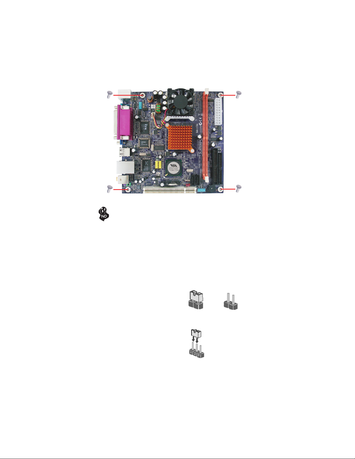
Installing the Motherboard in a Case
Refer to the following illustration and instructions for installing the motherboard in a case.
Most system cases have mounting brackets installed in the case, which correspond the holes
in the motherboard. Place the motherboard over the mounting brackets and secure the
motherboard onto the mounting brackets with screws.
Ensure that your case has an I/O template that supports the I/O ports and expansion slots
on your motherboard.
Installing the Motherboard
Page 14
8
Do not over-tighten the screws as this can stress the motherboard.
Checking Jumper Settings
This section explains how to set jumpers for correct configuration of the motherboard.
Setting Jumpers
Use the motherboard jumpers to set system configuration options. Jumpers with more than
one pin are numbered. When setting the jumpers, ensure that the jumper caps are placed on
the correct pins.
The illustrations show a 2-pin jumper. When
the jumper cap is placed on both pins, the
jumper is SHORT. If you remove the jumper
cap, or place the jumper cap on just one pin,
the jumper is OPEN.
This illustration shows a 3-pin jumper. Pins
1 and 2 are SHORT
SHORT OPEN
Installing the Motherboard
Page 15
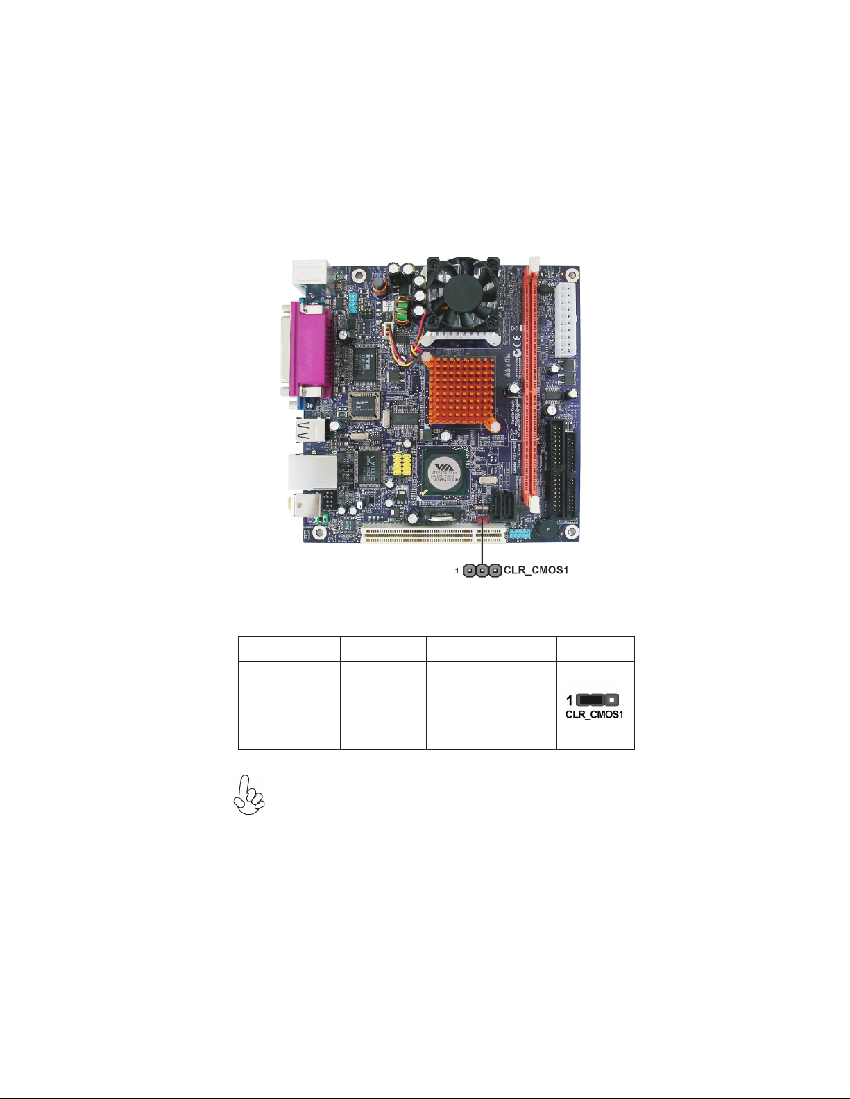
Checking Jumper Settings
The following illustration shows the location of the motherboard jumpers. Pin 1 is labeled.
9
Jumper Settings
Jumper Type Description Setting (default)
1-2: NORMAL
CLR_CMOS1
3-pin
CLEAR CMOS
To avoid the system unstability after clearing CMOS, we recommend users to
enter the main BIOS setting page to “Load Optimal Defaults” and then
“Save Changes and Exit”.
2-3: CLEAR CMOS
Before clearing the CMOS,
make sure to turn the system off.
Installing the Motherboard
Page 16
10
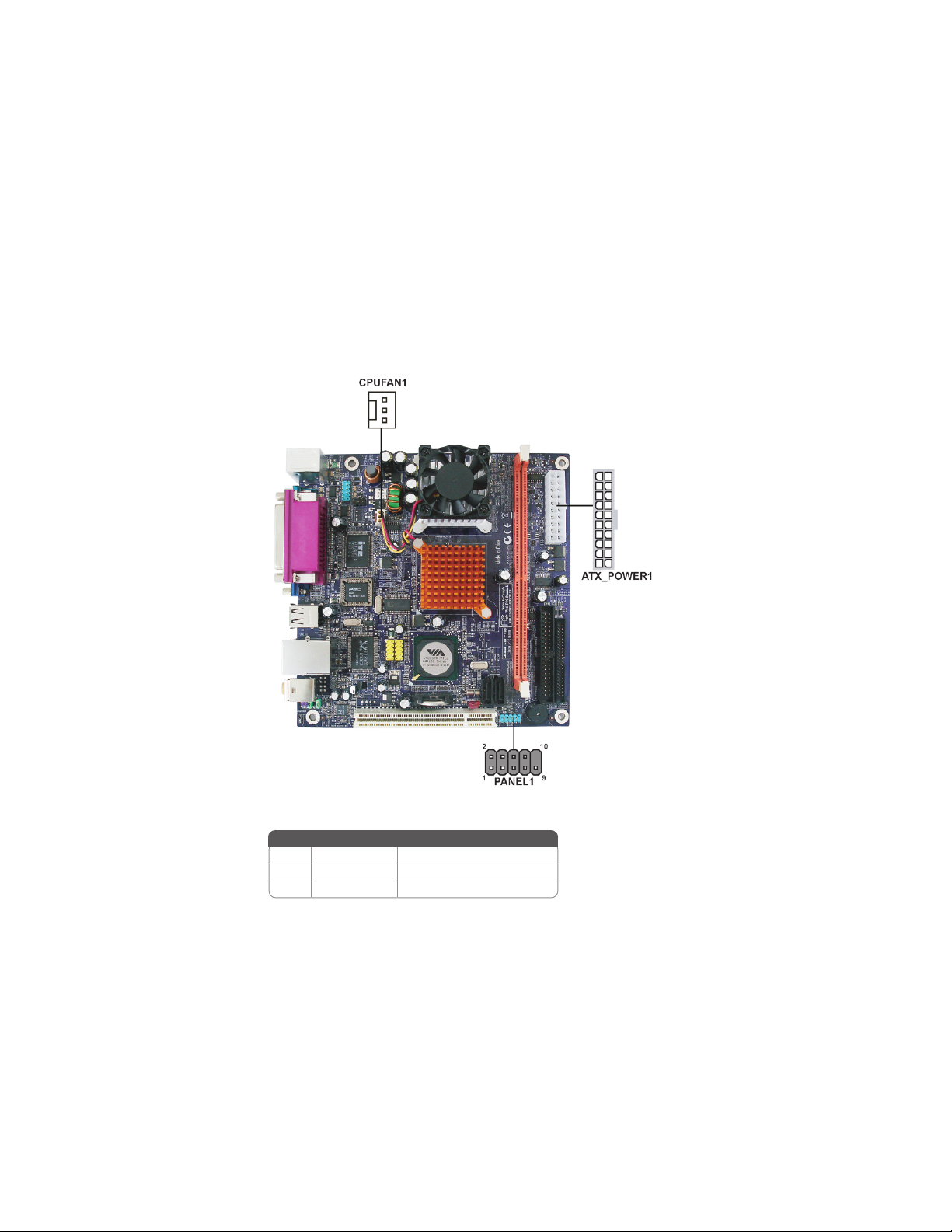
Connecting Case Components
After you have installed the motherboard into a case, you can begin connecting the motherboard components. Refer to the following:
1 Connect the CPU cooling fan cable to CPUFAN1.
2 Connect the case switches and indicator LEDs to the PANEL1.
3 Connect the standard power supply connector to ATX_POWER1.
CPU_FAN1: FAN Power Connector
Pin Signal Name Function
1 GND System Ground
2 +12V Power +12V
3 Sense Sensor
Installing the Motherboard
Page 17
ATX_POWER1: ATX 20-pin Power Connector
Pin Signal Name Pin Signal Name
1 VCC3 11 VCC3
2 VCC3 12 -12V
3 GND 13 GND
4 VCC 14 PS-ON#
5 GND 15 GND
6 VCC 16 GND
7 GND 17 GND
8 PWROK 18 -5V
9 5VSB 19 VCC
10 +12V 20 VCC
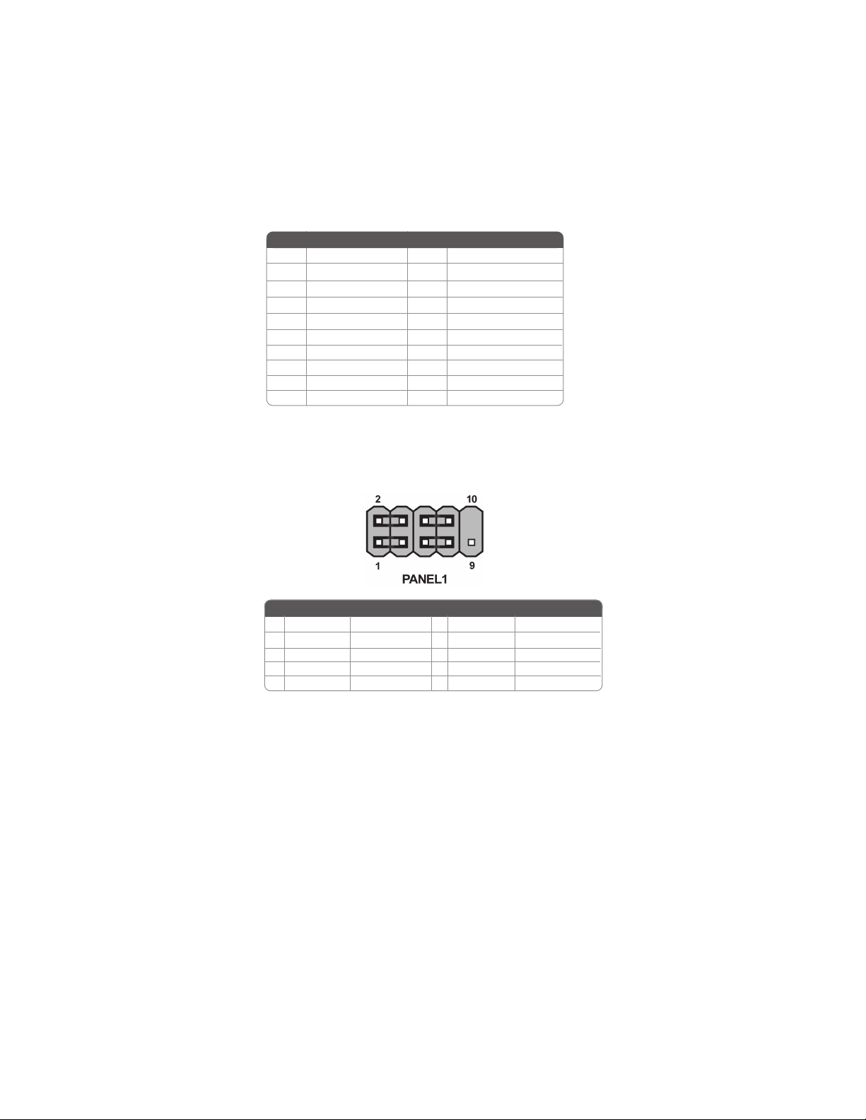
Front Panel Header
The front panel header (PANEL1) provides a standard set of switch and LED headers
commonly found on ATX or micro-ATX cases. Refer to the table below for information:
11
Pin Signal Name Function
1 HD_LED_P Hard Disk LED(+) 2 FP PWR/SLP *MSG LED(+)
3 HD_LED_N Hard disk LED(-)
5 RST_SW_N Reset Switch(-)
7 RST_SW_P Reset Switch(+)
9 RSVD_DNU Reserved
* MSG LED (dual color or single color)
Pin Signal Name Function
4 FP PWR/SLP *MSG LED(-)
6 PWR_SW_P Power Switch(+)
8 PWR_SW_N Power Switch(-)
10 Key No pin
Hard Drive Activity LED
Connecting pins 1 and 3 to a front panel mounted LED provides visual indication that data
is being read from or written to the hard drive. For the LED to function properly, an IDE
drive should be connected to the onboard IDE interface. The LED will also show activity
for devices connected to the SCSI (hard drive activity LED) connector.
Installing the Motherboard
Page 18

12
Power/Sleep/Message waiting LED
Connecting pins 2 and 4 to a single or dual-color, front panel mounted LED provides power
on/off, sleep, and message waiting indication.
Reset Switch
Supporting the reset function requires connecting pin 5 and 7 to a momentary-contact
switch that is normally open. When the switch is closed, the board resets and runs POST.
Power Switch
Supporting the power on/off function requires connecting pins 6 and 8 to a momentarycontact switch that is normally open. The switch should maintain contact for at least 50 ms
to signal the power supply to switch on or off. The time requirement is due to internal debounce circuitry. After receiving a power on/off signal, at least two seconds elapses before
the power supply recognizes another on/off signal.
Installing Hardware
Installing Memory Modules
This motherboard accommodates one memory module. It can support one 240-pin DDR2
533/400 DDR2 SDRAM. The total memory capacity is 1 GB.
DDR2 SDRAM memory module table
Memory module Memory Bus
DDR2 400 200MHz
DDR2 533 266MHz
You must install one module in the slot.The module can be installed with 1 GB; total
memory capability is 1 GB.
Do not remove any memory module from its antistatic packaging until
you are ready to install it on the motherboard. Handle the modules only
by their edges. Do not touch the components or metal parts. Always wear
a grounding strap when you handle the modules.
Installing the Motherboard
Page 19

Installation Procedure
Refer to the following to install the memory modules.
1 This motherboard supports unbuffered DDR2 SDRAM only.
2 Push the latches on each side of the DIMM slot down.
3 Align the memory module with the slot. The DIMM slots are keyed with notches
and the DIMMs are keyed with cutouts so that they can only be installed
correctly.
4 Check that the cutouts on the DIMM module edge connector match the notches
in the DIMM slot.
5 Install the DIMM module into the slot and press it firmly down until it seats
correctly. The slot latches are levered upwards and latch on to the edges of
the DIMM.
13
Installing the Motherboard
Page 20

14
Table A: DDR2 (memory module) QVL (Qualified Vendor List)
The following DDR2 memory modules have been tested and qualified for use with this
motherboard.
Typ e Size Vendor Module Name
DDR2 400
DDR2 533
Samsung M378T3354BZ0-CCC K4T51163QB-ZCCC
256 MB
Samsung M378T65 53BG0-CCC K4T51083QB-GCCC
512MB
TwinMos Samsung K4T51083QB-GCCC
Corsair Aeneon AET94F-370
Corsair VC256MB533D2 4PB11D9CHM
Eipida Eipida E2508AA-DF-E
Eipida Japan E2508AA-T7F-E
Hynix Hynix HY5PS121621
Kingmax Hynix HY5PS121621
256 MB
Kingston Elpida E5116F-5C-E
Kingston Infineon KVR533D2N4/256 HYB18T512260AF-3.7
Nanya Nanya NT5TU32M16AG-37B
Ramaxel Elpida D5116AF-5C-E
Ramaxel 5PB4 D9DCD
Twinmos Elpida 8D 22IB-ED
Corsair
Corsair VS512MB533D2 64M8CEC
Eipida Eipida 04180WB01
Hynix Hynix HY5PS12821
Infineon HY818T512 800AF37 33346778
Kingston Hynix HYB18T512800AF37
Kingston Hynix H Y5PS12821
512MB
Kingston Nanya NT5TU64M8 AE-37B
Ramaxel Elpida E5108AG-5C-E
Ramaxel 5PB32D9DCDN
Samsung PC2-4200U-4444-10-B1 K4T51083QF-ZCD5
Samsung PC2-4200U- 4444-12-DS K4T51083QC
Twinmos Elpida E5108AB-5C-E
Twinmos Samsung 8D22JB-KM
Apacer Eipida E5108AB-5C-E
Apacer K4T51083QC
Geil A016E2864T2AG8AKT5H120001
1GB
Infineon HY818T512 800AF37 33344539
Kingmax KKEA88E4AAKG-37
UMAX U2S12D30TP-5C
Samsung K4T51083QB-ZCD5
Installing the Motherboard
Page 21

Installing a Hard Disk Drive/CD-ROM/SATA Hard Drive
This section describes how to install IDE devices such as a hard disk drive and a CD-ROM
drive.
About IDE Devices
Your motherboard has a primary and secondary IDE channel interface (IDE1 and IDE2).
An IDE ribbon cable supporting two IDE devices is bundled with the motherboard.
You must orient the cable connector so that the pin1 (color) edge of the
cable corresponds to the pin 1 of the I/O port connector.
IDE1: Primary IDE Connector
The first hard drive should always be connected to IDE1.
15
IDE2: Secondary IDE Connector
The second drive on this controller must be set to slave mode. The configuration is the
same as IDE1.
IDE devices enclose jumpers or switches used to set the IDE device as MASTER or SLAVE.
Refer to the IDE device user’s manual. Installing two IDE devices on one cable, ensure that
one device is set to MASTER and the other device is set to SLAVE. The documentation of
your IDE device explains how to do this.
About UltraDMA
This motherboard supports UltraDMA 133/100/66/33. UDMA is a technology that accelerates the performance of devices in the IDE channel. To maximize performance, install
IDE devices that support UDMA and use 80-pin IDE cables that support UDMA 133/100/
66/33.
Installing the Motherboard
Page 22

16
About SATA Connectors
Your motherboard features two SATA connectors supporting a total of two drives. SATA
refers to Serial ATA (Advanced Technology Attachment) is the standard interface for the
IDE hard drives which are currently used in most PCs. These connectors are well designed
and will only fit in one orientation. Locate the SATA connectors on the motherboard and
follow the illustration below to install the SATA hard drives.
Installing Serial ATA Hard Drives
To install the Serial ATA (SATA) hard drives, use the SATA cable that supports the Serial
ATA protocol. This SATA cable comes with an SATA power cable. You can connect either
end of the SATA cable to the SATA hard drive or the connector on the motherboard.
SATA cable (optional)
Refer to the illustration below for proper installation:
1 Attach either cable end to the connector on the motherboard.
2 Attach the other cable end to the SATA hard drive.
3 Attach the SATA power cable to the SATA hard drive and connect the other
end to the power supply.
This motherboard does not support the “Hot-Plug” function.
SATA power cable (optional)
Installing the Motherboard
Page 23

Installing Add-on Cards
The slots on this motherboard are designed to hold expansion cards and connect them to the
system bus. Expansion slots are a means of adding or enhancing the motherboard’s features
and capabilities. With these efficient facilities, you can increase the motherboard’s capabilities by adding hardware that performs tasks that are not part of the basic system.
17
PCI1 Slot
This motherboard is equipped with one PCI slot. PCI stands for Peripheral
Component Interconnect and is a bus standard for expansion cards, which for
the most part, is a supplement of the older ISA bus standard. The PCI slot on
this board is PCI v2.2 compliant.
Before installing an add-on card, check the documentation for the card
carefully. If the card is not Plug and Play, you may have to manually
configure the card before installation.
Installing the Motherboard
Page 24

18
Follow these instructions to install an add-on card:
1 Remove a blanking plate from the system case corresponding to the slot you
are going to use.
2 Install the edge connector of the add-on card into the expansion slot. Ensure
that the edge connector is correctly seated in the slot.
3 Secure the metal bracket of the card to the system case with a screw.
For some add-on cards, for example graphics adapters and network adapters, you have to install drivers and software before you can begin using the
add-on card.
Installing the Motherboard
Page 25

Connecting Optional Devices
Refer to the following for information on connecting the motherboard’s optional devices:
IR1: Infrared header
19
Pin Signal Name Function
1 Not Assigned
2 K ey
3 + 5V
4 GND
5 IR_TX IrDA serial output
6 IR_RX IrDA serial input
Not assigned
No pin
IR Power
Ground
COM2: Onboard serial port header
Connect a serial port extension bracket to this header to add a second serial port to your
system.
Pin Signal Name Function
1 NDCDC/NDCDD Data Carrier Detect
2 NSINC/NSIND Serial Input
3 NSOUTC/NSOUTD UART B Serial Output
4 NDTRC/NDTRD UART B Data Terminal Ready
5 Ground Ground
6 NDSRC/NDSRD Data Set Ready
7 NRTSC/NRTSD RART B Request to Send
8 NCTSC/NCTSD Clear to Send
9 XNRI3/XNRI4 Ring Indicator
10 Key No pin
Installing the Motherboard
Page 26

20
AUDIO1: Front Panel Audio header
This header allows the user to install auxiliary front-oriented microphone and line-out ports
for easier access.
Pin Signal Name Function
1 AUD_MIC Front Panel Microphone input signal
2 AUD_GND Ground used by Analog Audio Circuits
3 AUD_MIC_BIAS Microphone Power
4 AUD_VCC Filtered +5V used by Analog Audio Circuits
5 AUD_FPOUT_R Right Channel Audio signal to Front Panel
6 AUD_RET_R Right Channel Audio signal to Return from Front Panel
7 HP_ON Reserved
8 Key No Pin
9 AUD_FPOUT_L Left Channel Audio signal to Front Panel
10 AUD_RET_L Left Channel Audio signal to Return from Front Panel
Pin Signal Name
F_USB1/2: Front Panel USB headers
The motherboard has four USB ports installed on the rear edge I/O port array. Additionally,
some computer cases have USB ports at the front of the case. If you have this kind of case,
use auxiliary USB connector to connect the front-mounted ports to the motherboard.
Pin Signal Name Function
1 VCC Power
2 VCC Power
3 USBP2-N Negative data signal of
4 USBP3-N Positive data signal of
5 USBP2-P Positive data signal of
6 USBP3-P Negative data signal of
7 GND System
8 GND System
9 Key No pin
10 OC# Over current detection of
Please make sure that the USB cable has the same pin assignment as
indicated above. A different pin assignment may cause damage or system
hang-up.
SATA1/2: Serial ATA connectors
These connectors are use to support the new Serial ATA devices for the highest date transfer
rates (1.5 Gb/s), simpler disk drive cabling and easier PC assembly. It eliminates limitations
of the current Parallel ATA interface. But maintains register compatibility and software
compatibility with Parallel ATA.
Pin Signal Name
Pin Signal Name Function
1 Ground 2 TX+
3 TX- 4 Ground
5 RX- 6 RX+
7 Ground - -
Pin Signal Name
Installing the Motherboard
Page 27

Connecting I/O Devices
The backplane of the motherboard has the following I/O ports:
21
PS2 Mouse
PS2 Keyboard
Parallel Port
(LPT1)
Serial Ports
(COM1)
VGA Port
LAN Port
(optional)
USB Ports
Audio Ports
Use the upper PS/2 port to connect a PS/2 pointing device.
Use the lower PS/2 port to connect a PS/2 keyboard.
Use the LPT1 to connect printer or other parallel communications
devices.
Use the COM ports to connect serial devices such as mice or fax/
modems.
Connect your monitor to the VGA port.
Connect an RJ-45 jack to the LAN port to connect your computer to the Network.
Use the USB ports to connect USB devices.
Use the two audio ports to connect audio devices. The first jack
is for stereo line-out signal. The second jack is for microphone.
This concludes Chapter 2. The next chapter covers the BIOS.
Installing the Motherboard
Page 28

22
Memo
Installing the Motherboard
Page 29

Chapter 3
Using BIOS
About the Setup Utility
The computer uses the latest Award BIOS with support for Windows Plug and Play. The
CMOS chip on the motherboard contains the ROM setup instructions for configuring the
motherboard BIOS.
The BIOS (Basic Input and Output System) Setup Utility displays the system’s configuration status and provides you with options to set system parameters. The parameters are
stored in battery-backed-up CMOS RAM that saves this information when the power is
turned off. When the system is turned back on, the system is configured with the values you
stored in CMOS.
The BIOS Setup Utility enables you to configure:
• Hard drives, diskette drives and peripherals
• Video display type and display options
• Password protection from unauthorized use
• Power Management features
The settings made in the Setup Utility affect how the computer performs. Before using the
Setup Utility, ensure that you understand the Setup Utility options.
This chapter provides explanations for Setup Utility options.
23
The Standard Configuration
A standard configuration has already been set in the Setup Utility. However, we recommend
that you read this chapter in case you need to make any changes in the future.
This Setup Utility should be used:
• when changing the system configuration
• when a configuration error is detected and you are prompted to make changes
to the Setup Utility
• when trying to resolve IRQ conflicts
• when making changes to the Power Management configuration
• when changing the password or making other changes to the Security Setup
Entering the Setup Utility
When you power on the system, BIOS enters the Power-On Self Test (POST) routines.
POST is a series of built-in diagnostics performed by the BIOS. After the POST routines are
completed, the following message appears:
Using BIOS
Page 30

24
Press DEL to enter SETUP
Pressing the delete key accesses the BIOS Setup Utility:
Phoenix-AwardBIOS CMOS Setup Utility:
Standard CMOS Features
Advanced BIOS Features Load Fail-Safe Defaults
Advanced Chipset Features Load Optimized Defaults
Integrated Peripherals Set Supervisor Password
Power Management Setup Set User Password
PnP/PCI Configurations Save & Exit Setup
PC Health Status Exit Without Saving
Esc: Quit
F10: Save & Exit Setup
Time, Date, Hard Disk Type...
Frequency/Voltage Control
BIOS Navigation Keys
The BIOS navigation keys are listed below:
KEY FUNCTION
Enter
+/-/PU/PD
ESC Exits the current menu
F1
F2
F5
F6
F7
F10
Move
Select
Value
General Help
Item Help
Previous Values
Fail-Safe Defaults
Optimized Defaults
Save
: Select Item
Using BIOS
Page 31

Updating the BIOS
You can download and install updated BIOS for this motherboard from the manufacturer’s
Web site. New BIOS provides support for new peripherals, improvements in performance,
or fixes for known bugs. Install new BIOS as follows:
1 If your motherboard has a BIOS protection jumper, change the setting to allow
BIOS flashing.
2 If your motherboard has an item called Firmware Write Protect in Advanced
BIOS features, disable it. (Firmware Write Protect prevents BIOS from being
overwritten.
3 Create a bootable system disk. (Refer to Windows online help for information
on creating a bootable system disk.)
4 Download the Flash Utility and new BIOS file from the manufacturer’s Web
site. Copy these files to the system diskette you created in Step 3.
5 Turn off your computer and insert the system diskette in your
computer’s diskette drive. (You might need to run the Setup Utility and change
the boot priority items on the Advanced BIOS Features Setup page, to force
your computer to boot from the floppy diskette drive first.)
6 At the A:\ prompt, type the Flash Utility program name and press <Enter>.
7 Type the filename of the new BIOS in the “File Name to Program” text box.
Follow the onscreen directions to update the motherboard BIOS.
8 When the installation is complete, remove the floppy diskette from the diskette
drive and restart your computer. If your motherboard has a Flash BIOS jumper,
reset the jumper to protect the newly installed BIOS from being overwritten.
Using BIOS
When you start the Setup Utility, the main menu appears. The main menu of the Setup
Utility displays a list of the options that are available. A highlight indicates which option is
currently selected. Use the cursor arrow keys to move the highlight to other options. When
an option is highlighted, execute the option by pressing <Enter>.
25
Some options lead to pop-up dialog boxes that prompt you to verify that you wish to
execute that option. Other options lead to dialog boxes that prompt you for information.
Some options (marked with a triangle
values for the option. Use the cursor arrow keys to scroll through the items in the submenu.
In this manual, default values are enclosed in parenthesis. Submenu items are denoted by a
triangle
.
) lead to submenus that enable you to change the
Using BIOS
Page 32

26
Standard CMOS Features
This option displays basic information about your system.
Phoenix-AwardBIOS CMOS Setup Utility
Standard CMOS Features
Date (mm:dd:yy) Wed , Jan 1 2003
Time (hh:mm:ss) 0 : 1 : 0
IDE Channel 0 Master [ST3802110A]
IDE Channel 0 Slave [None]
IDE Channel 1 Master [None]
IDE Channel 1 Slave [None]
IDE Channel 2 Master [None]
IDE Channel 3 Master [None]
Video [EGA/VGA]
Halt On
Base Memory 640K
Extended Memory 194 560K
Total Memory 195584 K
: Move Enter: Select +/-/PU/PD:Value F10:Save ESC:Exit F1: General Help
F5:Previous Values F6:Fail-Safe Defaults F7:Optimized Defaults
[All,But Keyboard]
Date and Time
The Date and Time items show the current date and time on the computer. If
you are running a Windows OS, these items are automatically updated whenever you make
changes to the Windows Date and Time Properties utility.
IDE Devices (None)
Your computer has two IDE channels (Primary and Secondary) and each channel can be
installed with one or two devices (Master and Slave). Use these items to
configure each device on the IDE channel.
Item Help
Menu Level
Change the day, month,
year and century
Press <Enter> to display the IDE submenu:
Phoenix-AwardBIOS CMOS Setup Utility
IDE Channel 0 Master
IDE HDD Auto-Detection [Press Enter]
IDE Channel 0 Master [Auto]
Access Mode [Auto]
Capacity 80 GB
Cylinder 38309
Head 16
Precomp 0
Landing Zone 38308
Sector 255
: Move Enter: Select +/-/PU/PD:Value F10:Save ESC:Exit F1: General Help
F5:Previous Values F6:Fail-Safe Defaults F7:Optimized Defaults
Item Help
Menu Level
To auto-detect the
HDD’s size, head... on
this channel
IDE HDD Auto-Detection (Press Enter)
Press <Enter> while this item is highlighted to prompt the Setup Utility to automatically
detect and configure an IDE device on the IDE channel.
Using BIOS
Page 33

If you are setting up a new hard disk drive that supports LBA mode, more
than one line will appear in the parameter box. Choose the line that lists
LBA for an LBA drive.
IDE Channel 0/1 Master/Slave IDE/Extended IDE Drives (Auto)
Leave this item at Auto to enable the system to automatically detect and configure IDE
devices on the channel. If it fails to find a device, change the value to Manual and then
manually configure the drive by entering the characteristics of the drive in the items
described below. Please noted that if you choose IDE Channel 2/3 Master, the item may
change to Extended IDE Drive.
Refer to your drive’s documentation or look on the drive casing if you need to obtain this
information. If no device is installed, change the value to None.
Before attempting to configure a hard disk drive, ensure that you have the
configuration information supplied by the manufacturer of your hard drive.
Incorrect settings can result in your system not recognizing the installed hard
disk.
Access Mode (Auto)
This item defines ways that can be used to access IDE hard disks such as LBA (Large Block
Addressing). Leave this value at Auto and the system will automatically decide the fastest
way to access the hard disk drive. If you choose IDE Channel 2/3 Master, the item only
have Large and Auto.
Press <Esc> to return to the Standard CMOS Features page.
27
Video (EGA/VGA)
This item defines the video mode of the system. This motherboard has a built-in VGA
graphics system; you must leave this item at the default value.
Halt On (All,But Keyboard)
This item defines the operation of the system POST (Power On Self Test) routine. You
can use this item to select which types of errors in the POST are sufficient to halt the
system.
Base Memory, Extended Memory, and Total Memory
These items are automatically detected by the system at start up time. These are
display-only fields. You cannot make changes to these fields.
Press <Esc> to return to the main menu setting page.
Using BIOS
Page 34

28
3
Advanced BIOS Features
This option defines advanced information about your system.
Phoenix-AwardBIOS CMOS Setup Utility
Advanced BIOS Features
CPU Feature
Hard Disk Boot Priority [Press Enter]
CPU L1 & L2 Cache [Enabled]
CPU L2 Cache ECC Checking [Enabled]
Quick Power On Self Test [Enabled]
First Boot Device [Hard Disk]
Second Boot Device [CDROM]
Thir d Boot Device [LS120]
Boot Other Device [Enabled]
Boot Up NumLock Status [On]
Typematic Rate Setting [Disabled]
Typematic Rate (Chars/Sec) 6
X
Typematic Delay (Msec) 250
X
Security Option [Setup]
MPS Version Control For OS [1.4]
OS Select For DRAM>64MB [Non-OS2]
Video BIOS Shadow [Enabled]
Small Logo (EPA) Show [Disabled]
: Move Enter: Select +/-/PU/PD:Value F10:Save ESC:Exit F1: General Help
F5:Previous Values F6:Fail-Safe Defaults F7:Optimized Defaults
CPU Features (Press Enter)
Scroll to this item and press <Enter> to view the following screen:
[Press Enter]
2
Menu Level
Item Help
Phoenix-AwardBIOS CMOS Setup Utility
1.Delay Prior to Thermal [16 Min]
: Move PU/PD:Value F10:Save ESC:Exit F1:General Help
Enter: Select +/-/
F5:Previous Values F6:Fail-Safe Defaults F7:Optimized Defaults
CPU Features
Item Help
Menu Level
Delay Prior to Thermal (16 Min)
Enables you to set the delay time before the CPU enters auto thermal mode.
Press <Esc> to return to the Advanced BIOS Features screen.
Using BIOS
Page 35

Hard Disk Boot Priority (Press Enter)
Scroll to this item and press <Enter> to view the following screen:
Phoenix-AwardBIOS CMOS Setup Utility
Hard Disk Boot Priority
1.Ch0 M. : ST3802110A
2. Bootable Add-in Cards
: Move PU/PD+/-/:Change Priority F10:Save ESC:Exit
F5:Previous Values F6:Fail-Safe Defaults F7:Optimized Defaults
Item Help
Menu Level
Use < > or < > to
select a device, then
press <+> to move it up,
or <-> to move it down
the list. Press <ESC>
to exit this menu.
Press <Esc> to return to the Advanced BIOS Features screen.
CPU L1 & L2 Cache (Enabled)
All processors that can be installed motherboard use CPU internal cache memory to improve performance. This item enables or disables the actual CPU internal level 1/2 cache
function. Leave this item at default value for better performance.
CPU L2 Cache ECC Checking (Enabled)
Enable this item to allow CPU L2 Cache ECC (Error Correcting Code) checking.
Quick Power On Self Test (Enabled)
Enable this item to shorten the power on testing (POST) and have your system start
up faster. You might like to enable this item after you are confident that your system
hardware is operating smoothly.
First/Second/Third Boot Device (Hard Disk/CDROM/LS120)
Use these three items to select the priority and order of the devices that your system
searches for an operating system at start-up time.
29
Boot Other Device (Enabled)
When enabled, the system searches all other possible locations for an operating system if
it fails to find one in the devices specified under the First, Second, and Third boot devices.
Boot Up NumLock Status (On)
This item defines if the keyboard Num Lock key is active when your system is started.
Typematic Rate Setting (Disabled)
If this item is enabled, you can use the following two items to set the typematic rate and the
typematic delay settings for your keyboard.
• Typematic Rate (Chars/Sec): Use this item to define how many characters
per second are generated by a held-down key.
Using BIOS
Page 36

30
• Typematic Delay (Msec): Use this item to define how many milliseconds
must elapse before a held-down key begins generating repeat characters.
Security Option (Setup)
If you have installed password protection, this item defines if the password is required at
system start up, or if it is only required when a user tries to enter the Setup Utility.
MPS Version Control For OS (1.4)
This item specifies which version of MPS of (Multi-Processor Specification) this
motherboard will use. Leave this item to its default setting.
OS Select For DRAM > 64 MB (Non-OS2)
This item is only required if you have installed more than 64 MB of memory and you are
running the OS/2 operating system. Otherwise, leave this item at the default.
Video BIOS Shadow (Enabled)
Enable this item to shadow basic BIOS function in ROM in order to invoke these
function whenever needs.
Small Logo (EPA) Show (Disabled)
Enables or disables the display of the EPA logo during boot.
Press <Esc> to return to the main menu setting page.
Using BIOS
Page 37

Advanced Chipset Features
These items define critical timing parameters of the motherboard. You should leave the
items on this page at their default values unless you are very familiar with the technical
specifications of your system hardware. If you change the values incorrectly, you may
introduce fatal errors or recurring instability into your system.
Phoenix-AwardBIOS CMOS Setup Utility
Advanced Chipset Features
DRAM Clock/Drive Control [Press Enter]
CPU & PCI Bus Control [Press Enter]
System BIOS Cacheable [Enabled]
Video RAM Cacheable [Disabled]
: Move Enter: Select +/-/PU/PD:Value F10:Save ESC:Exit F1: General Help
F5:Previous Values F6:Fail-Safe Defaults F7:Optimized Defaults
Item Help
Menu Level
31
DRAM Clock/Drive Control
(Press Enter)
Scroll to this item and press <Enter> to view the following screen:
Phoenix-AwardBIOS CMOS Setup Utility
DRAM Clock/Drive Control
Current FSB Frequency 100MHz
Current DRAM Frequency 200MHz
DRAM Clock
DRAM Timing
x
SDRAM CAS Latency [ DDR/DDR 2.5 / 4]
x
Bank Interleave Disabled
x
Precharge to Active (Trp) 4T
x
Active to Precharge (Tras) 07T
x
Active to CMD (Trcd) 4T
x
REF to ACT/REF (Trfc) 21T
x
ACT (0) to ACT(1) (TRRD) 3T
Read to Precharge (Trtp) [2T]
Write to Read CMD (Twtr) [1T/2T]
Write Recovery Time (Twr) [4T]
DRAM Command Rate [2T Command]
RDSAIT mode [Auto]
x
RDSAIT selection 03
: Move Enter: Select +/-/PU/PD:Value F10:Save ESC:Exit F1: General Help
F5:Previous Values F6:Fail-Safe Defaults F7:Optimized Defaults
[By SPD]
[Auto By SPD]
Item Help
Current FSB/DRAM Frequency (100MHz/200MHz)
This item displays current FSB/DRAM frequency.
Using BIOS
Menu Level
Page 38

32
DRAM Clock (By SPD)
This item sets the DRAM clock module.
DRAM Timing (Auto By SPD)
This item selects the DRAM timing mode.
• SDRAM CAS Latency (DDR/DDR 2.5/4): This item determines the operation
of DDR SDRAM memory CAS (column address strobe). It is recommended
that you leave this item at the default value. The 2.5T setting requires faster
memory that secifically supports this mode.
• Bank Interleave (Disabled): Depending on your SDRAM module structure,
the 4-Way setting can offer the best performance. If you choose the wrong
setting, the computer system will not run in a stable number.
• Precharge to Active (Trp):This item specifies the the amount of time from a
bank precharge request to when it can be activated. It is usually recommended you use the lowest Trp which your RAM and motherboard can run
stable with.
• Active to Precharge (Tras):This item specifies the the amount of time
required between an active command to a precharge command.
• Active to CMD (Trcd):This item specifies the the amount of time in cycles for
issuing an active command and the read/write commands.
• REF to ACT/REF (Trfc):This item means AutoRefresh period.
• ACT(0) to ACT(1) (TRRD): This item means ACT(0) to ACT(1) delay.
Read to Precharge (Trtp) (2T)
This item defines the precharge operation always starts one clock following the Read
command, independent of CAS Latancy.
Write to Read CMD (Twtr) (1T/2T)
This item species CMD between a valid write command and the next read command.
Write Recovery Time (Twr) (4T)
Use this item to specify the time measured from the last write datum is safely registered by
the DRAM.
DRAM Command Rate (2T Command)
When the host (northbridge locates the desired memory address, it then processors the wait
state of commands.
RDSAIT mode (Auto)
This item enable or disable the RDSAIT mode.
• RDSAIT selection:This item enable or disable to select the RDSAIT mode.
Press <Esc> to return to the Advanced Chipset Features page.
Using BIOS
Page 39

CPU & PCI Bus Control (Press Enter)
Scroll to this item and press <Enter> to view the following screen:
Phoenix-AwardBIOS CMOS Setup Utility
CPU & PCI Bus Control
PCI Master 0 WS Write [Enabled]
PCI Delay Transaction [Enabled]
VLink mode selection [By Auto]
VLink 8X Support [Enabled]
DRDY_Timing [Default]
: Move Enter: Select +/-/PU/PD:Value F10:Save ESC:Exit F1: General Help
F5:Previous Values F6:Fail-Safe Defaults F7:Optimized Defaults
Item Help
Menu Level
PCI Master 0 WS Write (Enabled)
This item determines whether the chipsets inserts a delay before any writes from the PCI
slots. If it is enabled, write requests to the PCI bus are executed immediately (with zero wait
states), if the PCI bus is ready to send data.
PCI Delay Transaction (Enabled)
This item is used to meet the latency of PCI cycles to and from the ISA bus.
VLink mode selection (By Auto)
This item controls the data transfer speed between the north and south bridge.
VLink 8X Support (Enabled)
Use this item to enable or disable VLink 8X support.
DRDY_Timing (Default)
This item specifies the timing of data ready.
33
Press <Esc> to return to the Advanced Chipset Features page.
System BIOS Cacheable (Enabled)
This feature is only valid when the system BIOS is shadowed. It enables or disables the
caching of the system BIOS ROM at F0000h-FFFFFh via the L2 cache. This greatly
speeds up accesses to the system BIOS.
Video RAM Cacheable (Disabled)
Disable or enable this item to read cache data from RAM.
Press <Esc> to return to the main BIOS setting page.
Using BIOS
Page 40

34
Integrated Peripherals
These options display items that define the operation of peripheral components on
the system’s input/output ports.
Phoenix-AwardBIOS CMOS Setup Utility
Integrated Peripherals
VIA OnChip IDE Device [Press Enter]
VIA OnChip PCI Device [Press Enter]
SuperIO Device [Press Enter]
Onboard LAN Device [Enabled]
Onboard LAN Boot ROM [Disabled]
: Move Enter: Select +/-/PU/PD:Value F10:Save ESC:Exit F1: General Help
F5:Previous Values F6:Fail-Safe Defaults F7:Optimized Defaults
VIA OnChip IDE Device (Press Enter)
Scroll to this item and press <Enter> to view the following screen:
Phoenix-AwardBIOS CMOS Setup Utility
VIA OnChip IDE Device
OnChip SATA
SATA Mode
IDE DMA transfer access [Enabled]
Onchip IDE Channel0 [Enabled]
Onchip IDE Channel1 [Enabled]
IDE Prefetch Mode [Enabled]
Primary Master PIO [Auto]
Primary Slave PIO [Auto]
Secondary Master PIO [Auto]
Secondary Slave PIO [Auto]
Primary Master UDMA [Auto]
Primary Slave UDMA [Auto]
Secondary Master UDMA [Disabled]
Secondary Slave UDMA [Disabled]
IDE HDD Block Mode [Enabled]
: Move Enter: Select +/-/PU/PD:Value F10:Save ESC:Exit F1: General Help
F5:Previous Values F6:Fail-Safe Defaults F7:Optimized Defaults
[Enabled]
[IDE]
Item Help
Menu Level
Item Help
Menu Level
OnChip SATA (Enabled)
Enables or Disables the build-in on-chip Serial ATA.
SATA Mode (IDE)
Use this item to select the mode of the Serial ATA.
IDE DMA transfer access (Enabled)
This item allows you to enable the transfer access of the IDE DMA then burst onto the PCI
bus and nonburstable transactions do not.
OnChip IDE Channel0/1 (Enabled)
Use this item to enable or disable the PCI IDE channels that are integrated on the
motherboard.
Using BIOS
Page 41

IDE Prefetch Mode (Enabled)
The onboard IDE drive interface supports IDE prefetching, for faster drive access. If you
install a primary and secondary add-on interface, set this field to Disable if the interface
does not support prefetching.
Primary/Secondary Master/Slave PIO (Auto)
Each IDE channel supports a master device and a slave device. These four items let you
assign the kind of PIO (Programmed Input/Output) was used by the IDE devices. Choose
Auto to let the system auto detect which PIO mode is best, or select a PIO mode from 0-4.
Primary/Secondary Master/Slave UDMA (Auto)
Each IDE channel supports a master device and a slave device. This motherboard supports
UltraDMA technology, which provides faster access to IDE devices.
If you install a device that supports UltraDMA, change the appropriate item on this list to
Auto. You may have to install the UltraDMA driver supplied with this motherboard in order
to use an UltraDMA device.
IDE HDD Block Mode (Enabled)
Enable this field if your IDE hard drive supports block mode. Block mode enables BIOS to
automatically detect the optimal number of block read and writes per sector that the drive
can support. It also improves the speed of access to IDE devices.
Press <Esc> to return to the Integrated Peripherals page.
VIA OnChip PCI Device (Press Enter)
Scroll to this item and press <Enter> to view the following screen:
Phoenix-AwardBIOS CMOS Setup Utility
VIA OnChip PCI Device
AC97 Audio [Auto]
OnChip USB Controller [All Enabled]
OnChip EHCI Controller [Enabled]
USB Emulation [ON]
x
USB Keyboard Support Enabled
x
USB Mo use Supp ort Enabled
Item Help
Menu Level
35
: Move Enter: Select +/-/PU/PD:Value F10:Save ESC:Exit F1: General Help
F5:Previous Values F6:Fail-Safe Defaults F7:Optimized Defaults
AC97 Audio (Auto)
This option allows you to control the onboard AC’ 97 audio. Disable this item if you are
going to install a PCI audio add-on card.
OnChip USB Controller (All Enabled)
This item enables users to enable or disable the onchip USB function, setting it to be USB1.1
or USB2.0 compatible.
OnChip EHCI Controller (Enabled)
Enable or disable the Onboard EHCI controller.
Using BIOS
Page 42

36
USB Emulation (ON)
• USB Keyboard Support (Enabled): Enabled this item if you plan to use a
keyboard connected through the USB port in a legacy operating system
(such as DOS) that does not support Plug and Play.
• USB Mouse Support (Enabled):Enable this item if you plan to use a mouse
connected through the USB port in a legacy operating system (such as DOS)
that does not support Plug and Play.
Press <Esc> to return to the Integrated Peripherals page.
SuperIO Device (Press Enter)
Scroll to this item and press <Enter> to view the following screen:
Phoenix-AwardBIOS CMOS Setup Utility
Onboard Serial Port 1 [3F8/IRQ4]
Onboard Serial Port 2 [2F8/IRQ3]
UART Mode Select [Normal]
x
UR2 Duplex Mode Half
Onboard Parallel Port [378/IRQ7]
Parallel Port Mode [Normal]
x
ECP Mode Use DMA 3
SuperIO Device
Item Help
Menu Level
: Move Enter: Select +/-/PU/PD:Value F10:Save ESC:Exit F1: General Help
F5:Previous Values F6:Fail-Safe Defaults F7:Optimized Defaults
Onboard Serial Port 1/2 (3F8/IRQ4)(2F8/IRQ3)
This option is used to assign the I/O address and interrupt request (IRQ) for onboard serial
port 1/2 (COM1/2).
UART Mode Select (Normal)
• UR2 Duplex Mode (Half):This field is available when UART Mode is set to
either ASKIR or IrDA. This item enables you to determine the infrared function
of the onboard infrared chip. The options are Full and Half (default). Fullduplex means that you transmit and send information simultaneously. Halfduplex is the tranmission of data in both directions, but only one direction at a
time.
Onboard Parallel Port (378/IRQ7)
This option is used to assign the I/O address and interrupt request (IRQ) for the onboard
parallel port.
Parallel Port Mode (Normal)
Enables you to set the data transfer protocol for your parallel port. There are four options:
SPP (Standard Parallel Port), EPP (Enhanced Parallel Port), ECP (Extended Capabilities
Port) and ECP+EPP.
• ECP Mode Use DMA (3):When the onboard parallel port is set to ECP mode,
the parallel port can use DMA 3 or DMA 1.
Press <Esc> to return to the Integrated Peripherals page.
Using BIOS
Page 43

Onboard LAN Device (Enabled)
Enables or disables the onboard LAN.
Onboard LAN Boot ROM (Disabled)
This item allows you to enable or disable the onboard LAN Boot ROM function.
Power Management Setup
This option lets you control system power management. The system has various powersaving modes including powering down the hard disk, turning off the video, suspending
to RAM, and software power down that allows the system to be automatically resumed
by certain events.
ACPI Suspend Type [S1(POS)]
HDD Power Down [Disabled]
Suspend Mode [Disabled]
Video Off Option [Suspend--> Off]
Video Off Method [V/H SYNC+Blank]
MODEM Use IRQ [3]
Soft-Off by PWRBTN [Instant-Off]
Run VGABIOS if S3 Resume [Auto]
Ac Loss Auto Restart [Off]
IRQ/Event Activity Detect [Press Enter]
Phoenix-AwardBIOS CMOS Setup Utility
Power Management Setup
Item Help
Menu Level
37
: Move Enter: Select +/-/PU/PD:Value F10:Save ESC:Exit F1: General Help
F5:Previous Values F6:Fail-Safe Defaults F7:Optimized Defaults
ACPI Suspend Type (S1(POS)
Use this item to define how your system suspends. In the default, S3 (STR), the suspend
mode is a suspend to RAM, i.e., the system shuts down with the exception of a refresh
current to the system memory.
HDD Power Down (Disabled)
The IDE hard drive will spin down if it is not accessed within a specified length of time.
Options are from 1 Min to 15 Min and Disable.
Suspend Mode(Disabled)
The CPU clock will be stopped and the video signal will be suspended if no Power
Management events occur for a specified length of time. Full power function will return
when a Power Management events is detected.
Video Off Option (Suspend —> Off)
This option defines if the video is powered down when the system is put into suspend mode.
Video Off Method (V/H SYNC+Blank)
This item defines how the video is powered down to save power. This item is set to DPMS
(Display Power Management Software) by default.
MODEM Use IRQ (3)
If you want an incoming call on a modem to automatically resume the system from a powersaving mode, use this item to specify the interrupt request line (IRQ) that is used by the
modem. You might have to connect the fax/modem to the motherboard Wake On Modem
connector for this feature to work.
Using BIOS
Page 44

38
Soft-Off by PWRBTN (Instant Off)
Under ACPI (Advanced Configuration and Power management Interface) you can create a
software power down. In a software power down, the system can be resumed by Wake Up
Alarms. This item lets you install a software power down that is controlled by the power
button on your system. If the item is set to Instant-Off, then the power button causes a
software power down. If the item is set to Delay 4 Sec. then you have to hold the power
button down for four seconds to cause a software power down.
Run VGABIOS if S3 Resume (Auto)
This item allows the system to initialize the VGA BIOS from S3 (Suspend to RAM) sleep
state.
Ac Loss Auto Restart (Off)
This item enables your computer to automatically restart or return to its last operating
status.
IRQ/Event Activity Detect (Press Enter)
Scroll to this item and press <Enter> to view the following screen:
Phoenix-AwardBIOS CMOS Setup Utility
IRQ/Event Activity Detect
PS2KB Wakeup Select [Hot Key]
PS2KB Wakeup from S3 [Disabled]
x
Power Button Lock Enabled
PS2MS Wakeup from S3 [Disabled]
Resume By USB(S3) [Disabled]
VGA [OFF]
LPT & COM [LPT/COM]
HDD & FDD
PCI Master [OFF]
Resume By PCI PME [Enabled]
Resume By RING [Disabled]
RTC Alarm Resume [Disabled]
x
Date (of Month) 0
x
Resume Time (hh:mm:ss) 0: 0: 0
IRQs Activity Monitoring [Press Enter]
[ON]
Item Help
Menu Level
When Select Password,
Please press ENTER
key to change Password
Max 8 numbers.
: Move Enter: Select +/-/PU/PD:Value F10:Save ESC:Exit F1: General Help
F5:Previous Values F6:Fail-Safe Defaults F7:Optimized Defaults
PS2KB Wakeup Select (Hot Key)
This item enables you to select any key, hot key or power key to allow keyboard
activity to awaken the system.
PS2KB Wakeup from S3 (Disabled)
This item enables or disables you to allow keyboard activity to awaken the system from S3
mode.
• Power Button Lock (Enabled): If you enabled this item, the system can
automatically resume by pressing power key on the keyboard, or typing in the
password.You must use an ATX power supply in order to use this feature.
PS2MS Wakeup from S3 (Disabled)
This item enables or disables you to allow mouse activity to awaken the system from S3
mode.
Using BIOS
Page 45

Resume by USB (S3) (Disabled)
This option allows the activity of the USB devices to wake up the system from S3 sleep
state.
VGA (OFF)
Use this item to enable power management unit to monitor VGA activities.
LPT & COM (LPT/COM)
Use this item to enable power management unit to monitor LPT or COM activities.
HDD & FDD (ON)
Use this item to enable power management unit to monitor HDD or FDD activities.
PCI Master (OFF)
This item enable or disable that the system will be waken up by PCI master command.
Resume by PCI PME (Enabled)
This item specifies whether the system will be awakened from power saving modes when
activity or input signal of the specified hardware peripheral or component is detected.
Resume by Ring (Disabled)
This item specifies whether the system will be awakened from power saving modes when
activity or input signal of WOL/WOM/Ring device is detected.
RTC Alarm Resume (Disabled)
When set to Enabled, additional fields become available and you can set the date (day of
the month), hour, minute and second to turn on your system. When set to 0 (zero) for
the day of the month, the alarm will power on your system every day at the specified
time.
• Date of Month: Use this item to define the date of month when using the RTC
alarm to resume the system.
• Resume Time (hh:mm:ss): Use this item to define the time when using the
RTC alarm to resume the system.
39
Press <Esc> to return to the Power Management Setup screen.
Using BIOS
Page 46

40
IRQs Activity Monitoring (Press Enter)
Scroll to this item and press <Enter> to view the following screen:
Phoenix-AwardBIOS CMOS Setup Utility
IRQs Activity Monitoring
Primary INTR [ON]
IRQ3 (COM 2)
IRQ4 (COM 1)
IRQ5 (LPT 2)
IRQ6 (Floppy Disk)
IRQ7 (LPT 1)
IRQ8 (RTC Alarm)
IRQ9 (IRQ2 Redir)
IRQ10 (Reserved)
IRQ11 (Reserved)
IRQ12 (PS/2 Mouse)
IRQ13 (Coprocessor)
IRQ14 (Hard Disk)
IRQ15 (Reserved)
: Move Enter: Select +/-/PU/PD:Value F10:Save ESC:Exit F1: General Help
F5:Previous Values F6:Fail-Safe Defaults F7:Optimized Defaults
[Disabled]
[Enabled]
[Enabled]
[Enabled]
[Enabled]
[Disabled]
[Disabled]
[Disabled]
[Disabled]
[Enabled]
[Enabled]
[Enabled]
[Disabled]
The screen enables you to set IRQs that will resume the system from a power saving
mode.
Set any IRQ ro Enabled to allow activity at the IRQ to wake up the system from a
power saving mode.
Item Help
Menu Level
Press <Esc> to return to the Power Management Setup screen.
Using BIOS
Page 47

PNP/PCI Configurations
These options configure how PnP (Plug and Play) and PCI expansion cards operate in
your system. Both the the ISA and PCI buses on the motherboard use system IRQs
(Interrup ReQuests) and DMAs (Direct Memory Access). You must set up the IRQ and
DMA assignments correctly through the PnP/PCI Configurations Setup utility for the
motherboard to work properly. Selecting PnP/PCI Configurations on the main program
screen displays this menu:
Phoenix-AwardBIOS CMOS Setup Utility
PnP/PCI Configurations
Reset Configuration Data
Resources Controlled By [Auto(ESCD)]
X
IRQ Resources Press Enter
PCI/VGA Palette Snoop [Disabled]
Assign IRQ For USB [Enabled]
: Move Enter: Select +/-/PU/PD:Value F10:Save ESC:Exit F1: General Help
F5:Previous Values F6:Fail-Safe Defaults F7:Optimized Defaults
[Disabled]
Item Help
Menu Level
Default is Disabled.
Select Enabled to reset
Extended System Configuration Data (ESCD) when
you exit Setup if you have
installed a new add-on and
the system reconfiguration
has caused such a serious
conflict that the OS cannot
boot.
41
Reset Configuration Data (Disabled)
If you enable this item and restart the system, any Plug and Play configuration data stored
in the BIOS Setup is cleared from memory.
Resouces Controlled By (Auto(ESCD)
You should leave this item at the default Auto (ESCD). Under this setting, the system
dynamically allocates resourcesPCI/VGA Palette Snoop (Disabled) to Plug and Play
devices as they are required.
If you cannot get a legacy ISA (Industry Standard Architecture) expansion card to work
properly, you might be able to solve the problem by changing this item to Manual, and
then opening up the IRQ Resources submenu.
• IRQ Resources [Press Enter]:In the IRQ Resources submenu, if you assign an IRQ to Legacy ISA, then that Interrupt Request Line is reserved for a
legacy ISA expansion card. Press <Esc> to close the IRQ Resources submenu.
PCI/VGA Palette Snoop (Disabled)
This item is designed to overcome problems that can be caused by some non-standard
VGA cards. This board includes a built-in VGA system that does not require palette
snooping so you must leave this item disabled.
Assign IRQ For USB (Enabled)
Enable or Disable this item when users are to assign IRQ for the USB interface onboard.
Using BIOS
Page 48

42
PC Health Status
On motherboards that support hardware monitoring, this item lets you monitor the
parameters for critical voltages, temperatures and fan speeds.
Phoenix-AwardBIOS CMOS Setup Utility
PC Health Status
Shutdown Temperature [Disabled]
CPU Vcore 0.99V
VDIMM 1.85V
CPU Temperature 30°C
SYSTEM Temperature 39°C
CPU FAN SPEED 6026 RPM
: Move Enter: Select +/-/PU/PD:Value F10:Save ESC:Exit F1: General Help
F5:Previous Values F6:Fail-Safe Defaults F7:Optimized Defaults
Shutdown Temperature (Disabled)
Enables you to set the maximum temperature the system can reach before powering down.
System Component Characteristics
These fields provide you with information about the systems current operating status. You
cannot make changes to these field.
Item Help
Menu Level
• CPU Vcore
• VDIMM
• CPU Temperature
• SYSTEM Temperature
• CPU FAN SPEED
Using BIOS
Page 49

Frequency/Voltage Control
This item enables you to set the clock speed and system bus for your system. The clock
speed and system bus are determined by the kind of processor you have installed in your
system.
Phoenix-AwardBIOS CMOS Setup Utility
Frequency/Voltage Control
43
Auto Detect PCI Clk [Enabled]
Spread Spectrum [+/- 0.20%]
CPU Host/AGP/PCI Clock 100/66/33Mhz
: Move Enter: Select +/-/PU/PD:Value F10:Save ESC:Exit F1: General Help
F5:Previous Values F6:Fail-Safe Defaults F7:Optimized Defaults
Item Help
Menu Level
Auto Detect PCI Clk (Enabled)
When this item is enabled, BIOS will disable the clock signal of free PCI slots.
Spread Spectrum (+/- 0.20%)
If you enable spread spectrum, it can significantly reduce the EMI (Electro-Magnetic
Interference) generated by the system.
CPU Host/AGP/PCI Clock (100/66/33 MHz)
This item allows you to select the CPU Host/AGP/PCI Clock frequency.
Press <Esc> to return to the main menu setting page.
Using BIOS
Page 50

44
Load Fail-Safe Defaults
This option opens a dialog box that lets you install fail-safe defaults for all appropriate
items in the Setup Utility: Press <Y> and the <Enter> to install the defaults. Press
<N> and then <Enter> to not install the defaults. The fail-safe defaults place no great
demands on the system and are generally stable. If your system is not functioning
correctly, try installing the fail-safe defaults as a first step in getting your system working
properly again. If you only want to install fail-safe defaults for a specific option, select
and display that option, and then press <F6>.
Load Optimized Defaults
This option opens a dialog box that lets you install optimized defaults for all appropriate
items in the Setup Utility. Press <Y> and then <Enter> to install the defaults. Press
<N> and then <Enter> to not install the defaults. The optimized defaults place demands on the system that may be greater than the performance level of the components,
such as the CPU and the memory. You can cause fatal errors or instability if you install
the optimized defaults when your hardware does not support them. If you only want to
install setup defaults for a specific option, select and display that option, and then press
<F7>.
Set Supervisor/User Password
When this function is selected, the following message appears at the center of the screen
to assist you in creating a password.
ENTER PASSWORD
Type the password, up to eight characters, and press <Enter>. The password typed now
will clear any previously entered password from CMOS memory. You will be asked to
confirm the password. Type the password again and press <Enter>. You may also press
<Esc> to abort the selection.
To disable password, just press <Enter> when you are prompted to enter password. A
message will confirm the password being disabled. Once the password is disabled, the
system will boot and you can enter BIOS Setup freely.
PASSWORD DISABLED
If you have selected “System” in “Security Option” of “BIOS Features Setup” menu,
you will be prompted for the password every time the system reboots or any time you try
to enter BIOS Setup.
If you have selected “Setup” at “Security Option” from “BIOS Features Setup” menu,
you will be prompted for the password only when you enter BIOS Setup.
Supervisor Password has higher priority than User Password. You can use Supervisor
Password when booting the system or entering BIOS Setup to modify all settings. Also
you can use User Password when booting the
system or entering BIOS Setup but can not modify any setting if Supervisor Password
is enabled.
Using BIOS
Page 51

Save & Exit Setup
Highlight this item and press <Enter> to save the changes that you have made in the
Setup Utility and exit the Setup Utility. When the Save and Exit dialog box appears,
press <Y> to save and exit, or press <N> to return to the main menu.
Exit Without Saving
Highlight this item and press <Enter> to discard any changes that you have made in the
Setup Utility and exit the Setup Utility. When the Exit Without Saving dialog box
appears, press <Y> to discard changes and exit, or press <N> to return to the main
menu.
If you have made settings that you do not want to save, use the “Exit
Without Saving” item and press <Y> to discard any changes you have
made.
This concludes Chapter 3. Refer to the next chapter for information on the software
supplied with the motherboard.
45
Using BIOS
Page 52

46
Memo
Using BIOS
Page 53

Chapter 4
Using the Motherboard Software
About the Software CD-ROM
The support software CD-ROM that is included in the motherboard package contains all the
drivers and utility programs needed to properly run the bundled products. Below you can find
a brief description of each software program, and the location for your motherboard
version. More information on some programs is available in a README file, located in the
same directory as the software.
Never try to install all software from folder that is not specified for use with
your motherboard.
Before installing any software, always inspect the folder for files named README.TXT,
INSTALL.TXT, or something similar. These files may contain important information that
is not included in this manual.
Auto-installing under Windows 98/ME/2000/XP
The Auto-install CD-ROM makes it easy for you to install the drivers and software for your
motherboard.
If the Auto-install CD-ROM does not work on your system, you can still install
drivers through the file manager for your OS (for example, Windows Explorer). Refer to the Utility Folder Installation Notes later in this chapter.
47
The support software CD-ROM disc loads automatically under Windows 98/ME/2000/XP.
When you insert the CD-ROM disc in the CD-ROM drive, the autorun feature will automatically bring up the install screen. The screen has three buttons on it, Setup, Browse CD and
Exit.
If the opening screen does not appear; double-click the file “setup.exe” in the
root directory.
Using the Motherboard Software
Page 54
48
Setup Tab
Setup Click the Setup button to run the software installation program. Select
Browse CD
Exit The EXIT button closes the Auto Setup window.
Application Tab
Lists the software utilities that are available on the CD.
Read Me Tab
Displays the path for all software and drivers available on the CD.
from the menu which software you want to install.
The Browse CD button is the standard Windows command that allows
you to open Windows Explorer and show the contents of the support
CD.
Before installing the software from Windows Explorer, look for a file
named README.TXT, INSTALL.TXT or something similar. This file
may contain important information to help you install the software
correctly.
Some software is installed in separate folders for different operating
systems, such as DOS, WIN NT, or WIN98/95. Always go to the correct
folder for the kind of OS you are using.
In install the software, execute a file named SETUP.EXE or INSTALL.EXE
by double-clicking the file and then following the instructions on the
screen.
Running Setup
Follow these instructions to install device drivers and software for the motherboard:
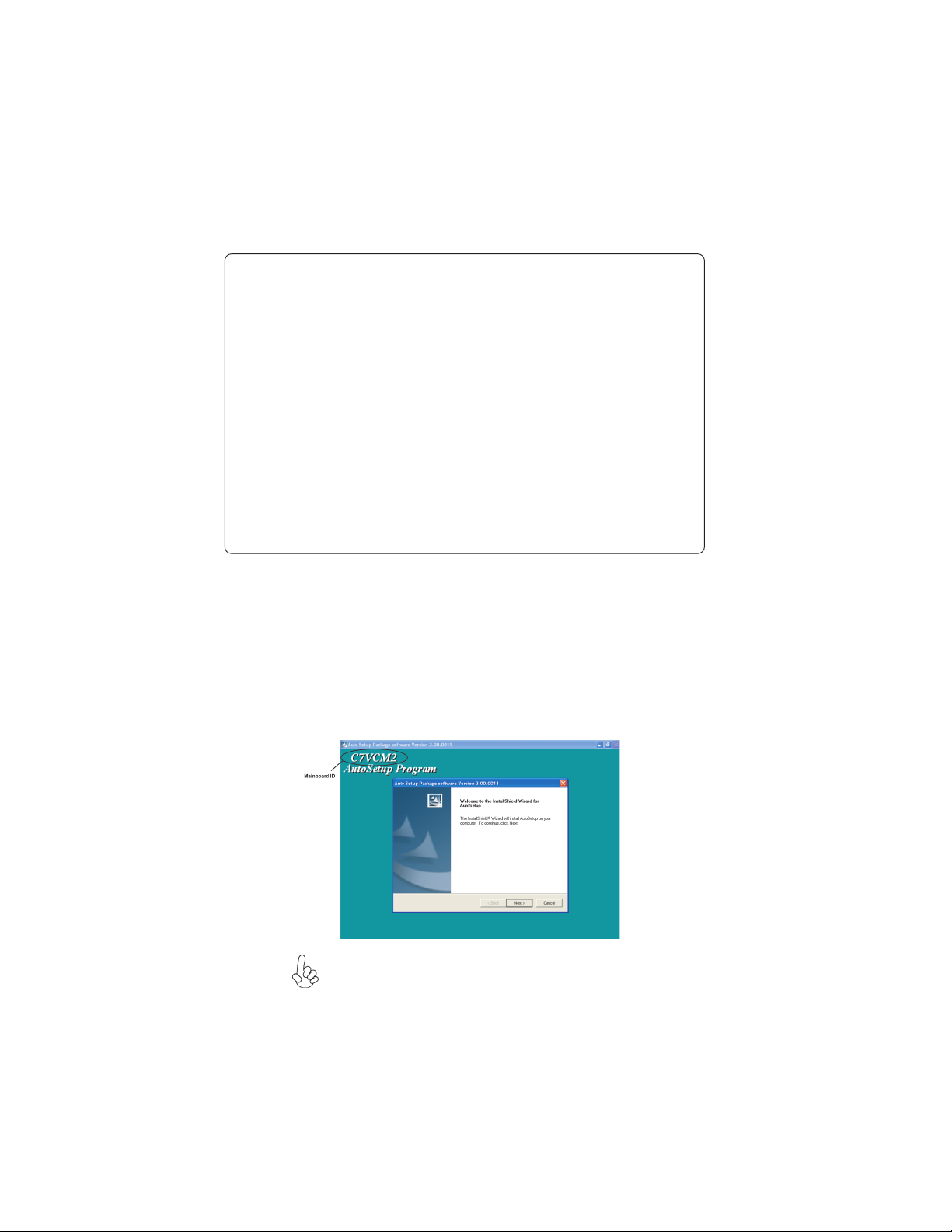
1. Click Setup. The installation program begins:
The following screens are examples only. The screens and driver lists will
be different according to the motherboard you are installing.
The motherboard identification is located in the upper left-hand corner.
Using the Motherboard Software
Page 55

2. Click Next. The following screen appears:
3. Check the box next to the items you want to install. The default options are recommended.
4. Click Next run the Installation Wizard. An item installation screen appears:
49
5. Follow the instructions on the screen to install the items.
Drivers and software are automatically installed in sequence. Follow the onscreen instructions, confirm commands and allow the computer to restart a few times to complete the
installation.
Using the Motherboard Software
Page 56

50
Manual Installation
Insert the CD in the CD-ROM drive and locate the PATH.DOC file in the root directory.
This file contains the information needed to locate the drivers for your motherboard.
Look for the chipset and motherboard model; then browse to the directory and path to
begin installing the drivers. Most drivers have a setup program (SETUP.EXE) that automatically detects your operating system before installation. Other drivers have the setup
program located in the operating system subfolder.
If the driver you want to install does not have a setup program, browse to the operating
system subfolder and locate the readme text file (README.TXT or README.DOC) for
information on installing the driver or software for your operating system.
Utility Software Reference
All the utility software available from this page is Windows compliant. They are provided
only for the convenience of the customer. The following software is furnished under license
and may only be used or copied in accordance with the terms of the license.
These software(s) are subject to change at anytime without prior notice.
Please refer to the support CD for available software.
This concludes Chapter 4.
Using the Motherboard Software
 Loading...