

Page 1

VGA User’s Manual
This publication, photographs, illustrations and software are under
the protection of international copyright laws and all rights
reserved. It does not allow any reproduction of this manual,
content and any materials contained herein without the written
consent of the authentic manufacturer.
The information in this manual is subject to change without notice
and without obligation to notify any person of such revision
change.
Macrovision Corporation Product Notice
This product incorporates copyright protection technology that is
protected by method claims of certain US. Patents and other
intellectual property rights owned by Macrovision Corporation and
other rights owners. Use of this copyright protection technology
must be authorized by Macrovision Corporation, and is intended
for home and other limited viewing uses only unless otherwise
authorized by Macrovision Corporation. Reverse engineering or
disassembly is prohibited.
Trademarks
All mentioned brands or product names are trademarks or
registered trademarks of their respective holders.
Copyright © 2003
All Rights Reserved
AG400 Series
XBR400/January 2003
V1.0
Page 2

VGA User’s Manual
II
Page 3

VGA User’s Manual
Table of Contents
Chapter 1 Introduction.....................................................................1
Key Features...................................................................2
Chapter 2 Hardware Installation......................................................5
Package Contents............................................................5
Card Layout....................................................................6
Jumper Settings..............................................................7
Connectors......................................................................8
Installing The Card.......................................................10
Chapter 3 Software Installation.....................................................11
Driver Installatin...........................................................11
VGA Utility.......................…………………………...13
III
Page 4

VGA User’s Manual
IV
Page 5

Chapter 1:Introduction
Chapter 1
Introduction
Congratulations on purchasing AG400 Series VGA Card, a high
performance graphics accelerator that enables you to experience
the realistic and exciting 3D world.
This VGA card uses a Xabre 400 GPU (Graphics Processing
Unit), the first generation chip of the SiS 256-bit GPU family.
Xabre GPU integrates an 8X/4X/2X AGP controller with full side-
band and pipeline support, a 256-bit 3D/2D graphics engine and a
motion compensation MPEG I /MPEG II accelerator. It offers a
complete 128-bit DDR 500MHz memory data bus. It can achieve
ultra high 2D performance with the maximum memory bandwidth
up to 7.1 GB/s. An optimized 3D pipeline architecture is
implemented for eliminating the overhead resulted from texture
read, Z-buffer read/write and destination read latencies and
achieving a sustain throughput of over 90% of peak throughput
when texture, Z buffer and alpha blending functions are all enabled.
Xabre GPU also includes a video accelerator and a high
performance DVD/HDTV motion compensation logic to provide
very smooth DVD/HDTV playback. Xabre GPU is accompanied
with built-in TV-Out chip SiS301 that integrates a NTSC/PAL
video encoder with Macro Vision Ver. 7.1.L1 option for TV
display.
AG400 Series enables a range of applications from 3D games to
HDTV, DVD, digital content creation, internet browsing and
general productivity. It is the best selection for your system.
1
Page 6

VGA User’s Manual
Key Features
♦ Chipset Xabre 400
-- AGP 8X/4X/2X 256-bit 3D/2D VGA card powered by
Xabre super graphics accelerator
-- Fully Microsoft DirectX8.1 & OpenGL ICD support for
Windows 98/2000/ME/XP
-- Memory Clock DDR 500MHz
-- Engine Clock (ECLK) 250 MHz
-- Maximum 375 MHz Palette-DAC
♦ AGP Interface
-- Supports AGP 3.0/2.0 compliant configuration setting
-- Supports AGP 8X 533MHz/4X with 16 stages
pipeline full side-band/pipe function
♦ High Performance & High Quality 3D Accelerator
-- Built-in 32-bit floating point format geometry transform/
lighting engine
-- Built-in hardware stereo auto rendering engine
-- Supports AGP 8X for texture/vertex fetch
-- Peak polygon rate: 25M polygon/sec @ 1 pixel/polygon
with Gouraud shaded, point-sampled, linear and bilinear
texture mapping
-- Peak fill rate: 1000 M pixel/sec, 2000 M texture/sec @
10,000 pixel/polygon with Gouraud shaded and two
bilinear textured
♦ High Performance 2D Accelerator
-- Built-in hardware command queue
-- Built-in Direct Draw Accelerator, and GDI 2000
Accelerator
-- Built-in an 1T pipelined 128-bit BITBLT graphics engine
-- Built-in 64x64x2 bit-mapped mono hardware cursor, and
64x64x16 bit-mapped blended color hardware cursor
-- Supports AGP 8X data read for all 2D engine
functions
2
Page 7
Chapter 1:Introduction
♦ MPEG-2 Video Decoder
-- MPEG-2 MP @ ML standards compliant
-- Built-in motion compensation logic
♦ Video Accelerator
-- Supports YUV-to-RGB color space conversion
-- Supports graphics and video overlay function
-- Supports tearing free double buffer flipping
-- Supports RGB555, RGB565, YUV422, and YUV420
video capture/playback format
♦ Complete TV-Out Solution (SiS301—for AG400T8-D64,
AG400-128TD and AG400-64TD)
-- Built-in complete NTSC/PAL video encoder
-- Supports VGA and TV simultaneous output with same or
different frame rate
♦ Resolution, Color & Frame Rate
-- Supports up to 375MHz pixel clock
-- Supports VESA standard super high resolution graphics
modes:
Resolutions Color Frame Rate
640x480 16/256/32K/64K/16M 85Hz NI
800x600 16/256/32K/64K/16M 85Hz NI
1024x768 256/32K/64K/16M 85Hz NI
1280x1024 256/32K/64K/16M 85Hz NI
1600x1200 256/32K/64K/16M 85Hz NI
1920x1440 256/32K/64K/16M 85Hz NI
2048x1536 256/32K/64K/16M 85Hz NI
♦ System Requirements:
-- Computer: Intel Pentium II/III/4 processor, Intel Celeron
processor, or compatible system
-- Expansion Slot: AGP slot
-- Monitor: VGA support, minimum 640x480 resolution
-- Operating system: Microsoft Windows
98/ME/NT/2000/XP, DX8.1 compatible
3
Page 8

VGA User’s Manual
♦ Bundled Software: (1) Driver
(2) Elite Castle 3 DNA Desktop
(3) WinDVD Creator
(4) WinDVD
(5) Game
4
Page 9

Chapter 2:Hardware Installation
Chapter 2
Hardware Installation
To install this AG400 Series VGA card, please follow the
instructions.
Package Contents
Attention: This VGA Card series has four models. Please check
with your vendor to make sure you have bought the product you
really want.
Model Specification
AG400T8-D64 Xabre400+SiS301, 64MB DDR
AG400E8-D64 Xabre400, 64MB DDR
AG400-64TD Xabre400+SiS301, 64MB DDR
AG400-128TD Xabre400+SiS301, 128MB DDR
Your card package should contain the following items:
♦ This User’s Manual
♦ The VGA card
♦ Super Software pack.
♦ One cable (optional)
♦ One adapter (optional)
Unpacking
♦ The card contains sensitive electric components, which can be
easily damaged by static electricity, so the card should be left
in its original packing until it is installed.
♦ Unpacking and installation should be done on a grounded
anti-static mat. The operator should be wearing an anti-static
wristband, grounded at the same point as the anti-static mat.
♦ Inspect the card carton for obvious damage. Shipping and
handling may cause damage to your card. Be sure there are no
shipping and handling damages on the card before
proceeding.
DO NOT APPLY POWER TO YOUR SYSTEM IF THE
CARD HAS BEEN DAMANGE.
5
Page 10

VGA User’s Manual
Card Layout
This diagram below identifies major components on the card.
XABRE 400
AG400T8-D64/AG400E8-D64
XABRE 400
AG400-64TD/AG400-128TD
6
Page 11
Chapter 2: Hardware Installation
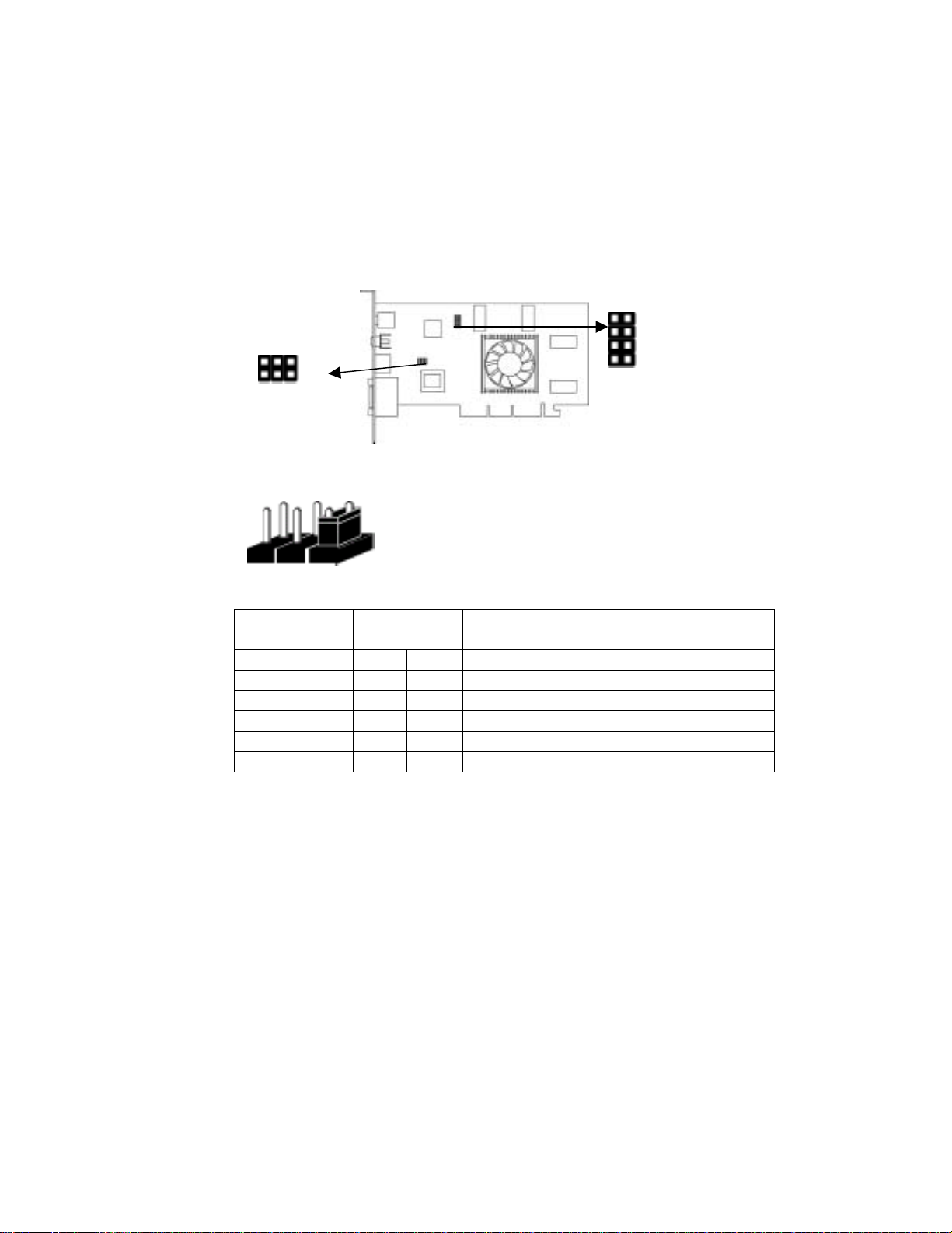
Jumper Settings
1
J3
1
2 4 6
J3
1 3 5
J3 Jumper
Pin1-2 Open NTSC
Short PAL
Pin3-4/Pin5-6 Open Open AGP(2.0) 2X Mode/AGP(3.0) 4X Mode
Open Short AGP(2.0) 4X Mode/AGP(3.0) 4/8X Mode
Short Open AGP(2.0) 1X Mode/AGP(3.0) 8X Mode
Short Short PCI Mode/Reserved
Default setting: Pin5-6 Short
Function
Setting
7
Page 12

VGA User’s Manual
N
X
N
X
N
7 5 3 1
J4
8 6 4 2
J4 Jumper
Pin1-2/Pin3-4 Open Open VGA
Open Short YUV
Short Open SCART TV
Short Short Normal TV
Pin5-6/Pin7-8 Open Open PAL (525I)
Open Short PAL-M (525P)
Short Open PAL-N (750P)
Short Short NTSC (1080I) HDTV
Default setting: All Short
Connectors
Function
Setting
3DCO
RCA
GPU
SCO
CRT
AG400T8-D64/AG400E8-D64
abre 400
DVI-I
SCO
CRT
AG400-64TD/AG400-128TD
GPU
abre 400
8
Page 13

Chapter 2: Hardware Installation
(op
)
(op
)
GPU
3DCON
DVI-I
RCA
SCON
CRT
Xabre 400
3DVR Connector
DVI-I Connector
TV-Out Composite
*TV-Out S-Video
for AG400T8-D64/AG400E8-D64
for AG400-64TD/ AG400-128TD
for AG400T8-D64/AG400E8-D64
for AG400T8-D64/ AG400E8-D64
*TV-Out AV/S-Video
VGA Connector
for AG400-64TD/ AG400-128TD
♦ 3DVR Connector—3DCON
You can connect a 3D glass device to obtain the 3D effect on
the screen.
♦ DVI (Digital Video Interface) Connector— DVI-I
It provides the monitor connection standard from the DDWG
(Digital Display Work Group), converting analog signals into
digital signals to accommodate both analog and digital
monitors. Users can also have the second CRT output by
connecting DVI to D-Sub adapter.
♦ TV-Out Composite/S-Video Connector—RCA/SCON
AG400T8-D64/AG400E8-D64 provide the Composite/
S-Video connectors, for video-out function, which allows you
to connect the TV or video input device.
♦ TV-Out AV/S-Video Connector—SCON
AG400-64TD/AG400-128TD provide AV/S-Video connector
(one bundled cable) for video-out function, which allows you
to connect the TV or video input device.
DVI to CRT Adapter
tional
SCON: 7-pin AV/S-Video Connector
S to AV transfer
cable
tional
♦ VGA Connector—CRT
AG400 Series provides a standard VGA connector that
allows you to connect a CRT monitor. Simply plug your
monitor cable into the VGA connector on your card, and make
sure that the other end of the cable is properly connected to
your monitor.
9
Page 14

VGA User’s Manual
Installing the Card
To install AG400 Series VGA card to your computer, please
follow the steps below:
1. Unplug the computer and remove the cover.
2. Insert the graphics accelerator card.
2-1. Locate the AGP slot on your mainboard.
2-2. Grasp the AG400 Series accelerator card by edges.
2-3. Align it with the empty AGP slot on the mainboard
and gently insert it into place. Make sure the card
evenly and completely seated in the slot.
3. Reconnect all cables and replace the cover.
10
Page 15

Chapter 3: Software Installation
Chapter 3
Software Installation
Driver Installation
Xabre Setup
When you insert the CD-ROM disc in the system CD-ROM drive,
the Xabre Setup main menu pops out. There are some buttons on
the screen:
Driver installation
includes the
VGA, AGP and
DirectX.
Utilities include
Elite Castle,
WinDVD IV and
WinDVD Creator.
Bundled games
It will launch the
browser to check
the CD content.
Readme
ECS contact
information
Note: The attached CD contains the contents subject to change
without notice.
11
Page 16

VGA User’s Manual
Please click the left buttons to install drivers.
All drivers will automatically detect the hardware and select a
suitable driver for users.
1. Again, please click the left buttons to install the utilities.
2. Follow the onscreen instructions to install the utilities.
12
Page 17

Chapter 3: Software Installation
VGA Utility
1.Click the right button of mouse, select and enter in the
following sequence: “Properties”—“Setting”—“Advance”—
“Utilities Manager”.
2. There are several icons on the “Utilities Manager” tab:
“Desktop Gamma Correction”, “Video Setting”, ”Driver Mode
Settings”, and “Product and File Information”.
13
Page 18

VGA User’s Manual
(
2-1.Desktop Gamma Correction: To adjust the color effect of
the current desktop.
Users can adjust
the total color
effect to be blue
or red (Hue).
Users can set up
each R/G/B value
by slide-bar.
Adjust the
brightness.
Adjust the Color
Enhancement
Saturation).
14
Page 19
Chapter 3: Software Installation
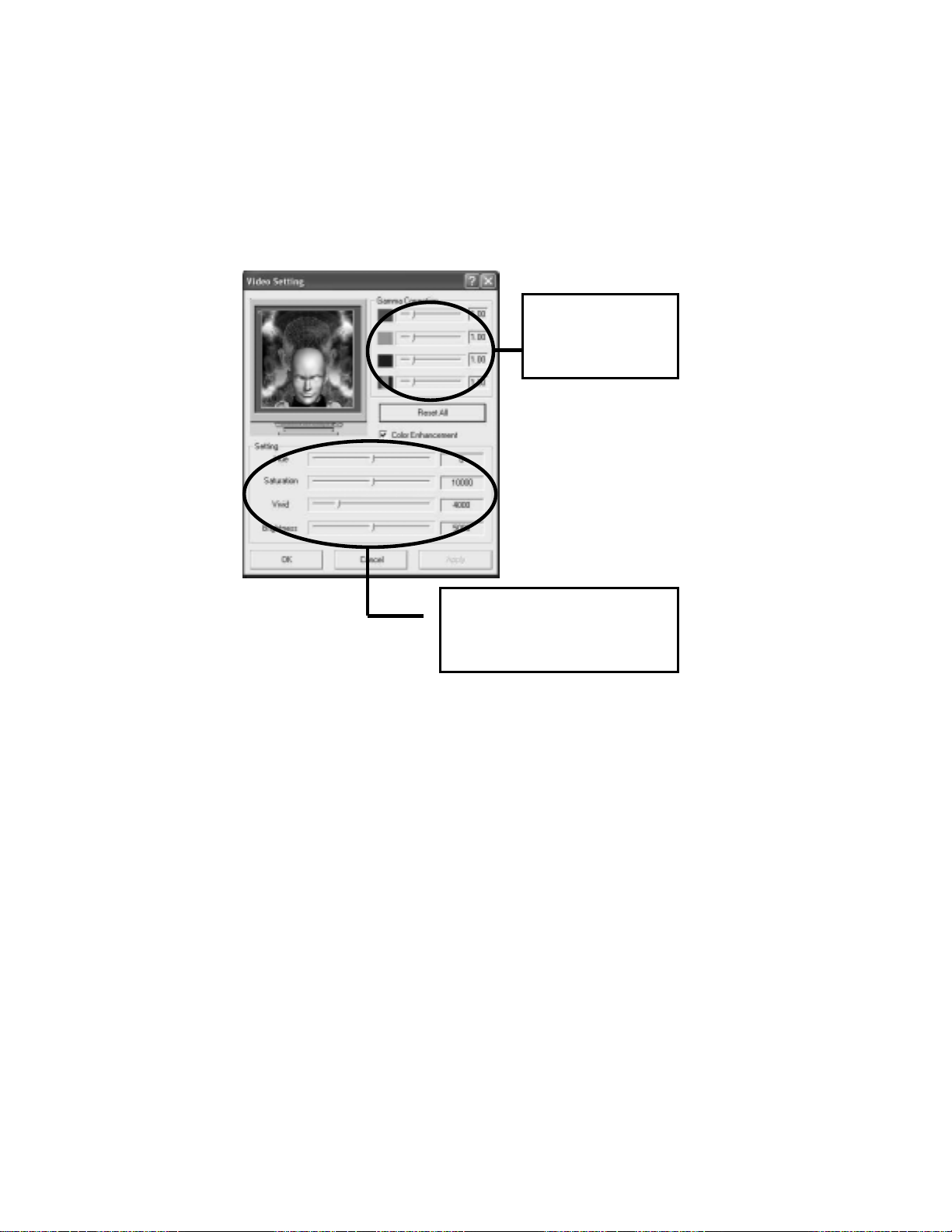
2-2 Video Setting: To adjust the video/overlay color effect.
Users can adjust the
color effect by each
R, G, B color value.
Of course, users can adjust the
color in an analogized method,
that is the Hue Saturation,
Brightness and Vivid.
15
Page 20
VGA User’s Manual
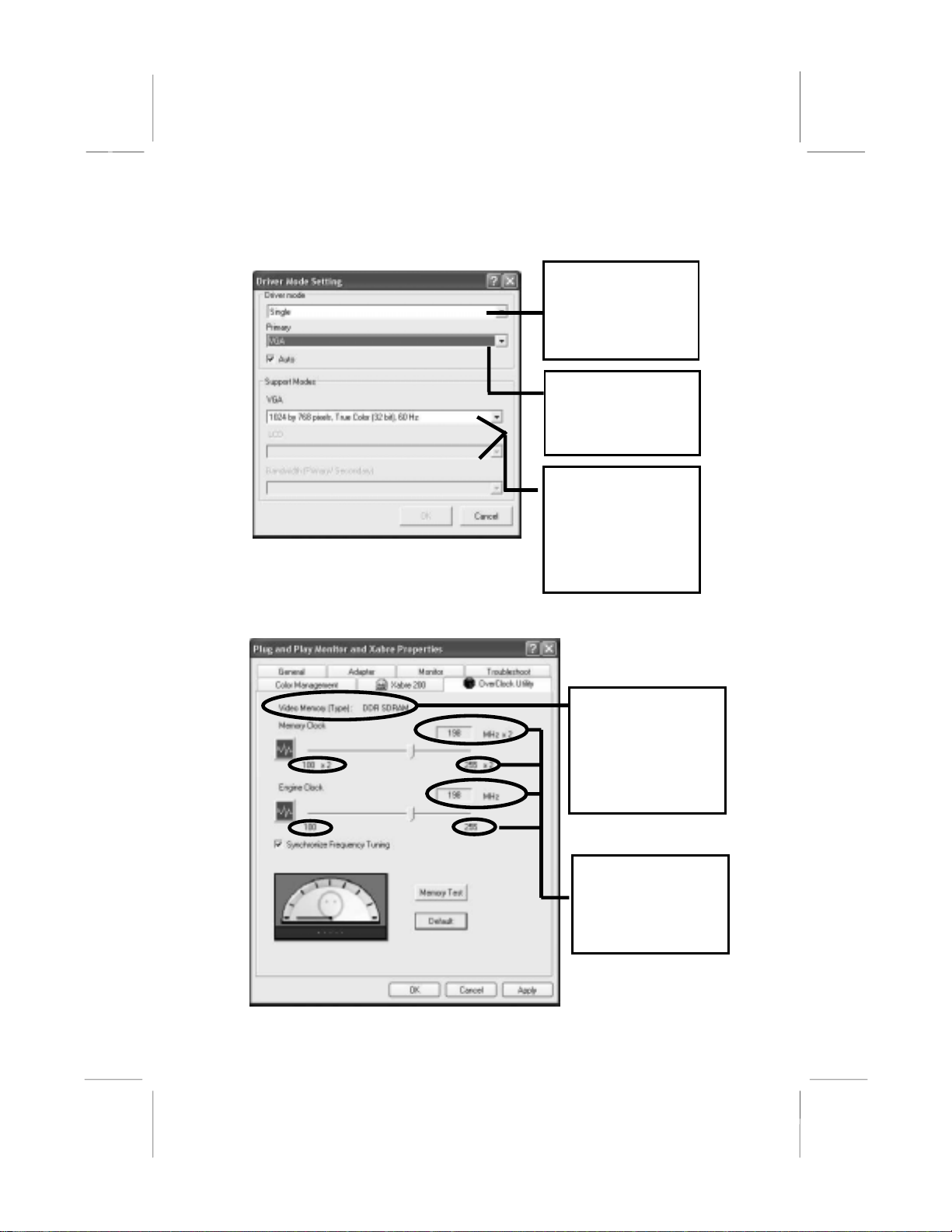
3. Driver Mode Setting
If users have more
than one display
output, they can
enable all output
devices or not.
It shows all available
output devices, and
users can select the
primary one!
According to the
selected device, this
pull-down menu will
list all available
modes and users can
select a desired mode
from the list.
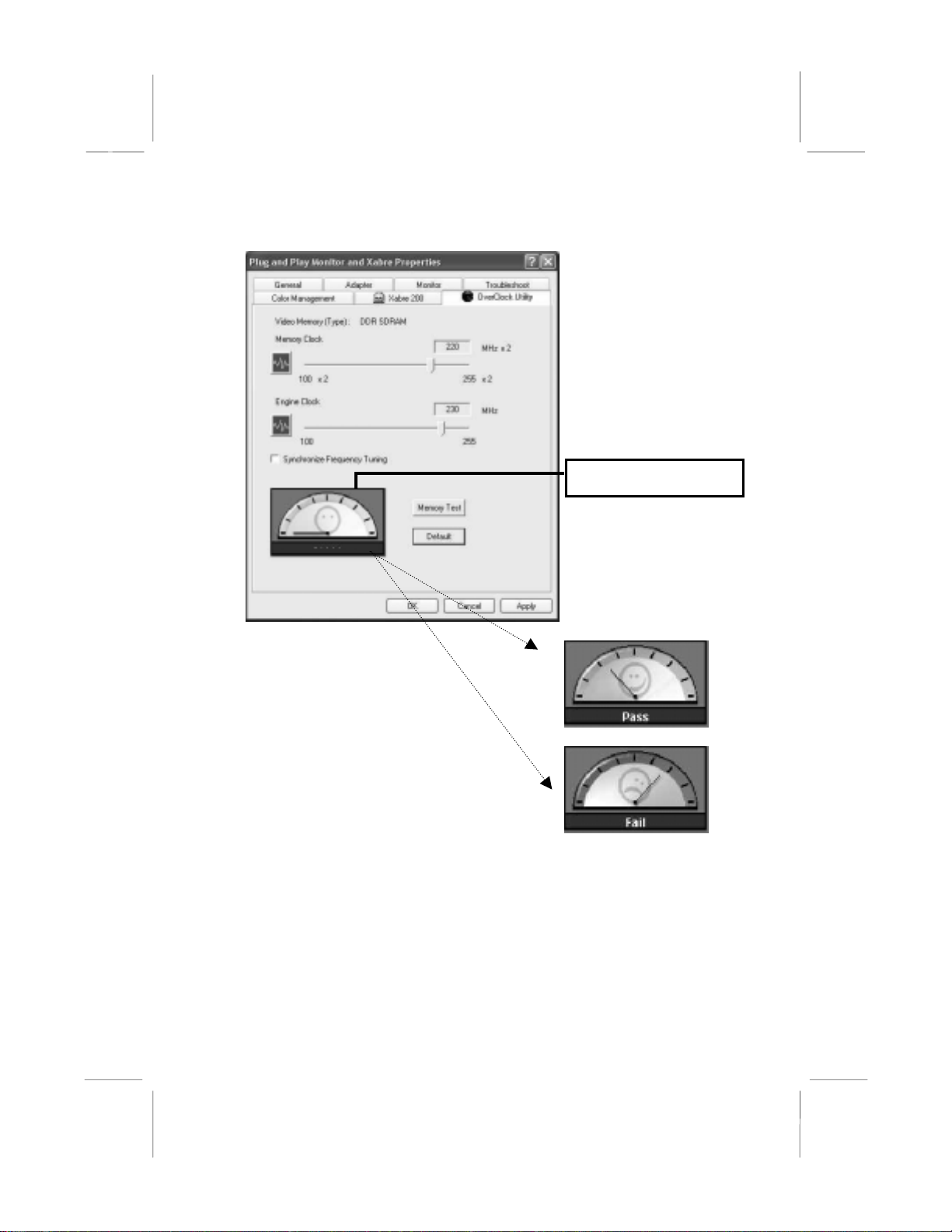
Smart Over-Clocking Utility (SOU)
SOU will
automatically detect
the memory type,
decide the clock
range of the mem
and the engine.
ory
16
At the first launch,
SOU will set up the
memory and engine
clock at the defaulted
value.
Page 21

Chapter 3: Software Installation
For the stability issue,
SOU will enable the
“Synchronize
Frequency Tuning” by
default.
It means SOU will
always set up the
same clock value for
both memory and
engine.
In this condition,
users can set up
different clock values
It may gain
performance.
Of course, users can
uncheck it.
After the clock is set up,
users can click this
button to test the stability
of the desired clock.
better
.
17
Page 22
VGA User’s Manual
Here is the testing result.
18
Or FAIL
Page 23
Chapter 3: Software Installation
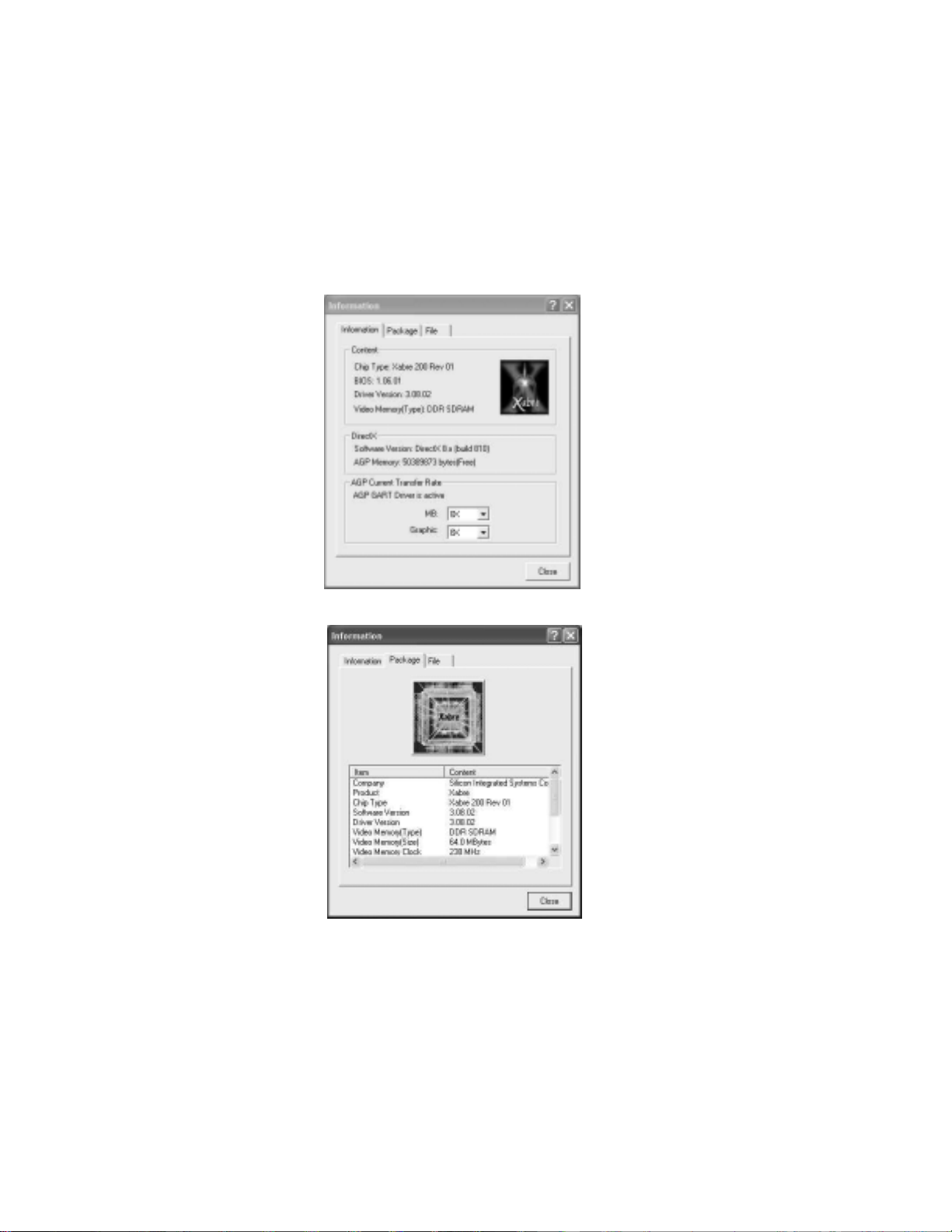
Integrated Information Page
For your convenience, here is the integrated information page
covering all relative details.
19
 Loading...