

Page 1

Mobile PC
Usseerr''ss
U
G
G
uii
u
dee
d
Page 2

Page 3

PPrreeffaaccee
Copyright 2003
All Rights Reserved.
Manual edition, September 2003
The information in this document is subject to change without prior notice in order
to improve reliability, design and function and does not represent a commitment
on the part of the manufacturer.
In no event will the manufacturer be liable for direct, indirect, special, incidental,
or consequential damages arising out of the use or inability to use the product or
documentation, even if advised of the possibility of such damages.
This document contains proprietary information protected by copyright. All rights
are reserved. No part of this manual may be reproduced by any mechanical,
electronic, or other means in any form without prior written permission of the
manufacturer.
TTrraaddeemmaarrkkss
CardSoft is a trademark of SystemSoft Corporation. AutoCAD and Autoshade are
trademarks of Autodesk, Inc. IBM, OS/2, and VGA are trademarks of International
Business Machines Corp. Lotus, 1-2-3, and Symphony are trademarks of Lotus
Development Corp. Windows, Word, MS-DOS, and Microsoft are trademarks of
Microsoft Corp. VESA is a trademark of Video Electronics Standards Association.
Other product names mentioned herein are used for identification purposes only
and may be trademarks and/or registered trademarks of their respective
companies.
LLiimmiittaattiioonn ooff LLiiaabbiilliittyy
While reasonable efforts have been made to ensure the accuracy of this manual,
the manufacturer and distributor assume no liability resulting from errors or
omissions in this manual, or from the use of the information contained herein.
Page 4

NNoottiicceess
FFeeddeerraall CCoommmmuunniiccaattiioonnss CCoommmmiissssiioonn RRaaddiioo FFrreeqquueennccyy IInntteerrffeerreennccee
SSttaatteemmeenntt
limits for a Class B digital device, pursuant to Part 15 of the FCC Rules.
These limits are designed to provide reasonable protection against harmful
interference in a residential installation. This equipment generates, uses,
and can radiate radio frequency energy and if not installed and used in
accordance with the instruction manual may cause harmful interference to
radio communications. However, there is no guarantee that interference
will not occur in a particular installation. If this equipment does cause
harmful interference to radio or television reception, which can be
determined by turning the equipment off and on, the user is encouraged to
try to correct the interference by one or more of the following measures:
• Reorient or relocate the receiving antenna.
• Increase the separation between the equipment and receiver.
• Connect the equipment into an outlet on a circuit different from that to
• Consult the dealer or an experienced radio TV technician for help.
This equipment has been tested and found to comply with the
which the receiver is connected.
ii
Page 5

NNoottiiccee::
Changes or modifications not expressly approved by the party responsible for
compliance could void the user’s authority to operate the equipment. Shielded
interface cables and a non-shielded AC power cord must be used in order to
comply with emission limits.
This equipment is to be used with power supply:
I/P: 100-240 Vac, 50-60Hz, 1.6A max
O/P: 19Vdc, 3.16A
There is no internal power supply.
CCaannaaddiiaann DDOOCC NNoottiiccee FFoorr CCllaassss BB CCoommppuuttiinngg DDeevviicceess
This Class B digital apparatus meets all requirements of the Canadian
Interference - Causing Equipment Regulations.
Cet appareil numerique de la classe B repecte toutes les exigences du Règlement
sur le matèriel brouilleur du Canada.
SSaaffeettyy PPrreeccaauuttiioonnss
This section is designed to assist you in identifying potentially unsafe conditions
while working with this product. Required safety features have been installed in
the computer to protect you from injury. However, you should use good judgment
to identify potential safety hazards:
Please read these safety instructions carefully.
11..
Please keep this User's Manual for later reference.
22..
Please disconnect this equipment from AC outlet before cleaning. Don't use
33..
liquid or sprayed detergent for cleaning. Use moisture sheet or cloth for
cleaning.
- iii -
Page 6

For pluggable equipment, that the socket-outlet shall be installed near the
44..
equipment and shall be easily accessible.
Please keep this equipment from humidity.
55..
Lay this equipment on a reliable surface when isntall. A drop or fall could
66..
cause injury.
Make sure to use the right voltage for the power source when connecting the
77..
equipment to the power outlet.
Place the power cord in such a way that people can not setp on it. Do not
88..
place anything on top of the power cord.
All cautions and warnings on the equipment should be noted.
99..
If the equipment is not use for a long time, disconnect the equipment from the
1100..
main power outlet to avoid being damaged by transient overvoltage.
Never pour any liquid into the opening, this could cause fire or electrical shock.
1111..
Never open the equipment. For safety reason, the equipment should only be
1122..
opened by a qualified service personnel.
iv
If on the following situations arises, get the equipment checked by a service
1133..
personnel:
The Power cord or plug is damaged.
aa..
Liquid has penetrated into the equipment.
bb..
The equipment has been exposed to moisture.
cc..
The equipment has not work well or you cannot get it work according to the
dd..
user's manual.
The equipment has dropped and damaged.
ee..
Page 7

If the equipment has obvious sign of breakage.
ff..
Do not leave this equipment in an environment unconditioned, storage
1144..
temperature above 60°C (140°f), it may damage the equipment.
The unit can be operated at an ambient temperature of max. 35°C.
1155..
The sound pressure level at the operators position according to IEC 704-1:
1166..
1982 is equal or less than 70 dB(A).
Power Cord Requirements
1177..
The power cord set used with the AC adaptor must meet the requirements of
the country where you use the AC adaptor, whether it is 100-120 or 200-240
Vac. The following information explains the requirements for power cord set
selection.
• The cord set must be approved for the country in which it is used.
• The appliance coupler must have a configuration for mating with a
CEE22/EN6032/IEC 320 appliance inlet.
A. For U.S. and Canada:
• The cord set must be UL Listed and CSA Certified.
• The minimum specifications for the flexible cord are No. 18 AWG.
B. For Japan:
• All components of the cord set must bear a “ T ” mark and
registration number in accordance with the Japanese Dentori Law.
• The minimum specifications for the flexible cord are .75m ㎡
conductors.
C. For Other Countries:
• The cord set fittings must bear the certification mark of the agency
responsible for evaluation in a specific country.
- v -
Page 8

• The flexible cord must be of a HAR (harmonized) type H05VV-F.
• The cord set must have a current capacity of a least 2.5 Amperes
and voltage rating of 125 or 250 Vac.
When using your telephone equipment, basic safety precautions should
1188..
always be followed to reduce the risk of fire, electric shock and injury to
persons. These precautions includes the following:
1. Do not use this product near water, for example, near a bathtub,
washbowl, kitchen sink or laundry tub, in a wet basement or near a
swimming pool.
2. Avoid using a telephone (other than a cordless type) during an
electrical storm. There may be a remote risk of electric shock from
lightning.
3. Do not use the telephone to report a gas leak in the vicinity of the
leak.
4. Use only the power cord indicated in this manual.
Do not use the AC adapter near open water or other liquids. Never spill liquid
1199..
into the AC adapter.
Laser Warning: Laser Class I Product Caution - Invisible laser radiation when
2200..
open avoid exposure to beam.
vi
Danger of explosion if battery is incorrectly replaced. Replace only with the
2211..
same or equivalent type recommended by the manufacturer. Dispose of used
batteries according to the manufacturer's instructions. Never remove the
battery pack while the power is on as this may result in data loss when the
system loses power.
Page 9

WWiicchhttiiggee SSiicchheerrhheeiittsshhiinnwweeiissee
Bitte lesen Sie diese Hinweis sorgfältig durch.
11..
Heben Sie dirse Anleitung für den späteren Gebrauch auf.
22..
Vor jedem Reinigen ist das Gerät vom Stromnetz zu trennen. Versenden Sie
33..
Keine Flüssig- oder Aerosolreiniger. Am besten eignet sich ein
angefeuchtetes Tuch zur Reinigung.
Die Netzanschluβsteckdose soll nahe dem Gerät angebracht und leicht
44..
zugänglich sein.
Das Gerät ist vor Feuchtigkeit zu schützen.
55..
Bei der Aufstellung des Gerätes ist auf sicheren Stand zu achten. Ein Kippen
66..
oder Fallen könnte Beschädigungen hervorrufen.
Beachten Sie beim Anschluß an das Stromnet die Anschlußwerte.
77..
Verlegen Sie die Netzanschlußleitung so, daß niemand darüber fallen kann.
88..
Es sollte auch nichts auf der Leitun abgestellt werden.
Alle Hinweise und Warnungen, die sich am Gerät befinden, sind zu beachten.
99..
Wird das Gerät üeinen längeren Zeitraum nicht benutzt, sollten Sie es vom
1100..
Stromnetz trennen. Somit wird im Falle einer Überspannung eine
Beschädigung vermieden.
Durch die Lüftungsöffnungen dürfen niemals Gegenstände oder Flüssigkeien
1111..
in das Gerät gelangen. Dies könne einen Brand bzw. Elektrischen Schlag
auslösen.
Öffnen Sie niemals das Gerät. Das Gerät darf aus Gründen der elektrischen
1122..
- vii -
Page 10

Sicherheit nur von authorisiertem Servicepersonal geöffnet werden.
Wenn folgende Situationen auftreten ist das Gerät vom Stromnetz zu trennen
1133..
und von einer qualifizierten Servicestelle zu Überprüfung.:
Netzlabel oder Netzstecker sind beschädigt.
aa..
Flüssigkeit ist in das Gerät eingedrungen.
bb..
Das Gerät war Feuchtigkeit ausgesetzt.
cc..
Wenn das Gerät nicht der Bedienungsanleitung entsprechend funktioniert oder
dd..
Sie mit Hilfe dieser Anleitung keine Verbesserung erzielen.
Das Gerät ist gefallen und/oder das Gehäuse ist beschädigt.
ee..
Wenn das Gerät deutliche Anzeichen eines Defektes aufweist.
ff..
VORSICHT: Explosiongsgetahr bei unsachgemäßen Austausch der Batterie.
1144..
Ersatz nur durch denselben oder einem vom Hersteller empfohlenem
ähnlichen Typ. Entsorgung gebrauchter Batterien nach Angaben des
Herstellers.
Dieses Schaltnetzteil kann bis zu einer Außentemperatur von maximal 35ºC.
1155..
Die Ausgangswerte dürfen nicht die auf dem Label angegebenen Werte
1166..
überschreiten.
viii
Anforderungen an das Stromkabel
1177..
Das Kabel-Set, das an das Netzteil angeschlossen wird, muss den
Anforderungen des Landes, in dem Sie das Netzteil einsetzen, genügen, je
nachdem, ob die Netzspannung 100-120 oder 200-240V Wechselspannung
beträgt.
• Das Kabel-Set muss für das Land, in dem es eingesetzt wird,
zugelassen sein.
• Der Gerätestecker des Kabels muss in eine CEE22/ EN603/ IEC
320 Buchse passen.
Page 11

A. Für die USA und Kanada:
• Das Kabel-Set muss UL-gelistet und CSA zertifiziert sein.
• Die Minimalanforderungen für das Kabel entsprechen No. 18 AWG.
B. Für Japan:
• Alle Teile des Kabel-Sets müssen entsprechend dem japanischen
Dentori Law mit einem “T”-Symbol markiert sein
• Die Minimalanforderungen für das Kabel sind .75m ㎡ Leiter.
C. Für andere Länder:
• Die Zubehörteile des Kabel-Sets müssen das Prüfsiegel derjenigen
Stelle, die in dem jeweiligen Land für die Sicherheitsprüfung
zuständig ist, tragen.
• Das Kabel muss vom HAR (harmonisierten) Typ H05VV-F sein.
• Das Kabel-Set muss eine Stromkapazität von mindestens 2,5
Ampere haben und Spannungen von 125 oder 250 V Wechselstrom
gestatten.
Bei der Benutzung Ihres Telefongerätes sollten Sie immer die grundlegenden
1188..
Sicherheitsmaßnahmen beachten, um das Risiko von Feuer, Stromschlägen
und Verletzungen zu minimieren. Zu beachten sind u.a. folgende Punkte:
1. Benutzen Sie das Gerät nicht in der Nähe von Wasser, wie zum
Beispiel Badewanne, Waschbecken, Spülbecken, Waschbottich, in
feuchten Kellerräumen oder in der Nähe von Schwimmbecken.
2. Benutzen Sie kein Telefon (ausgenommen schnurlose Modelle)
während eines Gewitters. Es besteht das geringe Restrisiko eines
Blitzschlages.
3. Benutzen Sie das Telefon nicht um ein Gasleck zu melden, falls es
sich in der Nähe des Lecks befindet.
4. Benutzen Sie nur solch ein Stromkabel, wie in dieser Anleitung
beschrieben.
- ix -
Page 12

Benutzen Sie das Netzteil nicht in unmittelbarer Nähe zu Wasser oder
1199..
anderen Flüssigkeiten. Gießen Sie nie Flüssigkeiten über das Netzteil.
Achtung Laser: Laser Produkt der Klasse I. Achtung - Unsichtbarer
2200..
Laserstrahl, vermeiden Sie Kontakt mit dem Strahl bei offenem Gehäuse.
Es besteht Explosionsgefahr, wenn der Akku nicht ordnungsgemäß ersetzt
2211..
wird. Ersetzen Sie den Akku nur durch einen Akku gleichen oder äquivalenten
Typs, der vom Hersteller empfohlen wird. Entsorgen Sie Akkus entsprechend
den Anweisungen des Herstellers. Entfernen Sie den Akku auf keinen Fall bei
eingeschaltetem Mobile PC, da hierdurch Daten verloren gehen könnten.
x
Page 13

PPeerrssoonnaall IInnvveennttoorryy
This Mobile PC system is designed for years of productive and pleasurable
computing. Use this section to keep notes about details of your purchase.
Update this section when you add new options.
Date of Purchase:
Dealer’s Name:
Phone:
Address:
E-Mail Address:
WWW Site:
Serial Number:
CPU Type:
Hard Disk Capacity:
Memory Capacity:
Optional Equipment:
- xi -
Page 14

Page 15

Chapter 1
nttrr
IIn
o
o
d
uccttii
d
u
o
o
n
n
- 1 -
Page 16

TThhiinnggss yyoouu mmuusstt rreemmeemmbbeerr bbeeffoorree wwoorrkkiinngg oonn yyoouurr ccoommppuutteerr
LLeett yyoouurr ccoommppuutteerr aacccclliimmaattee iittsseellff
Your Mobile PC can easily stand temperature extremes but it doesn’t like rapid
changes in temperature, like going from the cold outdoors to a warm office. Rapid
changes in temperature can cause water droplets to condense inside your case,
threatening to damage the electronic parts inside.
After receiving your Mobile PC when it’s hot or cold outside, try not to power up
the computer immediately, let the computer adjust to the room temperature
gradually at least for three to four hours
If your system arrives in cold weather, do not apply power to
the computer or monitor until they have been allowed to come to room
temperature
HHeeaatt,, CCoolldd,, HHuummiiddiittyy,, aanndd GGllaarree
2
Find a suitable place for your computer that’s not too hot, too cold, too dark, or too
bright. Glare can make it hard to read the screen.
• Try to avoid the computer components from being destroyed if it is over
heated, so try to allow plenty of room for air to circulate around the case.
• Do not block the ventilation opening.
• Do not place your computer in direct sunlight.
Page 17

AA ffeeww ttiippss ttoo hheellpp yyoouu wwoorrkk eeffffeeccttiivveellyy wwiitthhoouutt aa lloott ooff pphhyyssiiccaall
ddiissccoommffoorrtt::
• Purchase a chair with armrests and good back support. Don't slouch when
sitting; keep your back straight.
• Try to place the LCD panel or external monitor so that there is little glare
from the sun on the monitor.
• Walk around the room every hour.
• Every half hour look away from the computer screen for a few minutes.
• Place everything that you need to work within easy reach.
WWeellccoommee ttoo tthhee MMoobbiillee PPCC
Congratulations on your purchase of the Mobile PC. Your Mobile PC features the
latest advances in portable computing technology. The Mobile PC’s modular
design provides maximum expandability without compromising portability. The
high-performance CPU and enhanced IDE hard drive provides you with extra
processing power for handling complex graphics and running large programs.
GGeettttiinngg ttoo KKnnooww YYoouurr CCoommppuutteerr
OOppeenniinngg tthhee LLCCDD PPaanneell
At the front of the Mobile PC you will find a retaining latch on the display panel
that locks the display in closed position when the Mobile PC is not in use.
Slide the display panel latch to the right until the display panel releases, and
11..
then raise the LCD screen.
- 3 -
Page 18

At any time you can tilt the display toward or away from you to a comfortable
22..
viewing position.
To avoid damage to the display panel:
1. Try not to slam the display upon closing it.
2. Try not to place any object on top when it is closed or open.
3. Be sure the system is turned off or in suspend mode before you close
the display panel.
With the LCD screen open, you will see several features important for operating
your Mobile PC.
4
Page 19

- 5 -
Page 20

Each of these features is briefly described below.
LCD Screen
Your Mobile PC is equipped with a replaceable color Liquid Crystal Display (LCD)
screen that supports up to 1024 x 768 x 32 bit LCD resolution utilizing a PCI BUS.
A built-in backlight allows you to comfortably view the screen even when ambient
lighting is low.
Power/Resume Button
Pressing this button for 1-2 seconds will turn on the system or pressing this button
when the computer is in Suspend mode will resume normal operation. Pressing this
button for 4-6 seconds will also turn off the system.
System Status Indicator Panel
The system status indicator panel keeps you informed of the computer’s operating
status.
Indicates that the computer is accessing the hard disk drive.
6
Indicates that the keyboard is in Num Lock mode.
Indicates when the keyboard is in Caps Lock mode. In this mode, the
keyboard produces uppercase text when you press a key. When you
press the Caps Lock key again, the indicator goes off and the keyboard
produces lowercase text.
Indicates when the keyboard is in Scroll Lock mode. Some applications
will move information across the screen differently when Scroll Lock is on.
Page 21

Indicates when the system LAN is functioning.
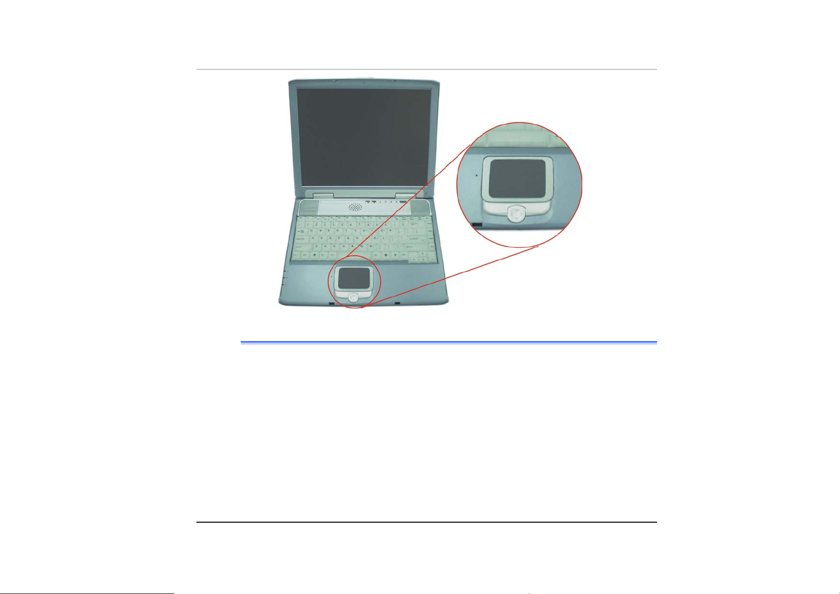
TouchPad
The TouchPad is hardware-compatible with the IBM PS/2 mouse and softwarecompatible with the Microsoft mouse.
TouchPad Buttons
The buttons below the TouchPad correspond to the left and right buttons on a
standard mouse. The PS/2 compatible mouse will work with the Mobile PC’s
TouchPad simultaneously.
Internet Explorer Button
Use this key to open the Internet Explorer.
Outlook Express Button
Use this key to open Microsoft's Outlook to send/receive your mail.
The Built-in Microphone
The built-in microphone is located to the left of the TouchPad.
Scroll Button
Use this button to scroll up and down or left and right the scrolling bar.
- 7 -
Page 22
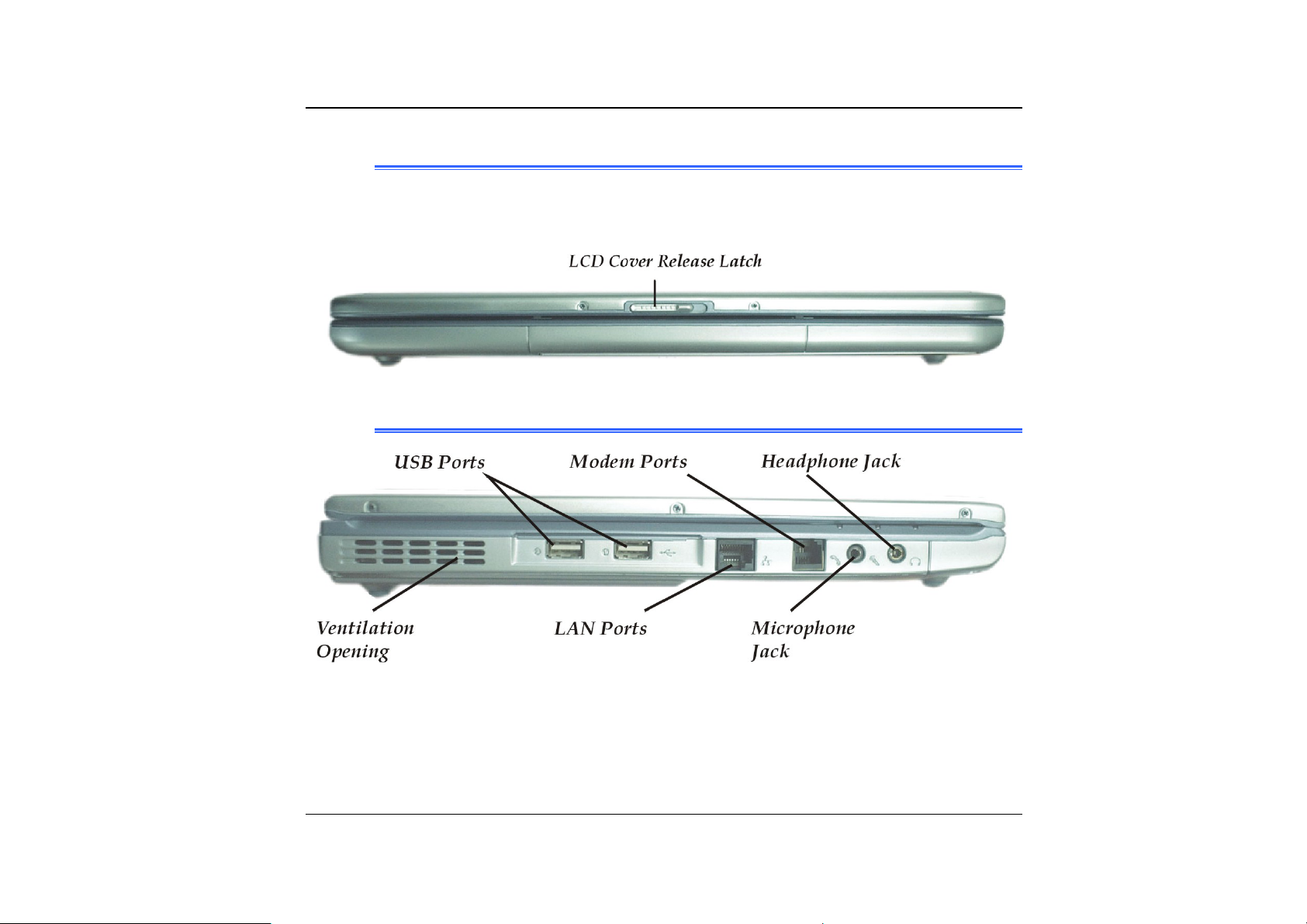
FFrroonntt SSiiddee
LCD Cover Release Latch
Slide this latch to the right to open the LCD cover.
TThhee LLeefftt SSiiddee
8
Ventilation Opening
Please don’t block this opening during operation of the system.
Page 23

The LAN Port
This jack provides a standard RJ-45 connection for integration with an existing
network or a high-speed (DSL or cable) connection via a network cable.
When using a LAN, please use an EMI Shielding Cable to
minimize an inteference when transmitting.
The Modem Port
This jack is an internal 56K voice/fax/data modem. You will connect your computer
to your phone line through this port.
Always disconnect all telephone lines from the wall outlet
before servicing or disassembling this equipment. To reduce the risk of
fire use only No. 26 AWG or larger telecommunication line cord.
Microphone Jack
Allows you to receive monophonic input from an external microphone. Use of an
external microphone will disable the built-in microphone.
Headphone Jack
You can plug an external speaker, headphone or connect the line out jack to an
audio device such as a cassette recorder to record the Mobile PC's audio output.
- 9 -
Page 24

LLEEDD IInnddiiccaattoorrss
These three LED indicators are separately program for the following functions:
Power On, Suspend Mode and Battery Charge.
10
1. Power On
This indicator will lit when the Mobile PC is powered On.
2. Battery Charge
This indicator will lit orange when the battery is in charging status. The
indicator will shut down when the battery is fully charged.
Page 25
3. Suspend Mode
This indicator will lit when the Mobile PC enter the suspend mode.
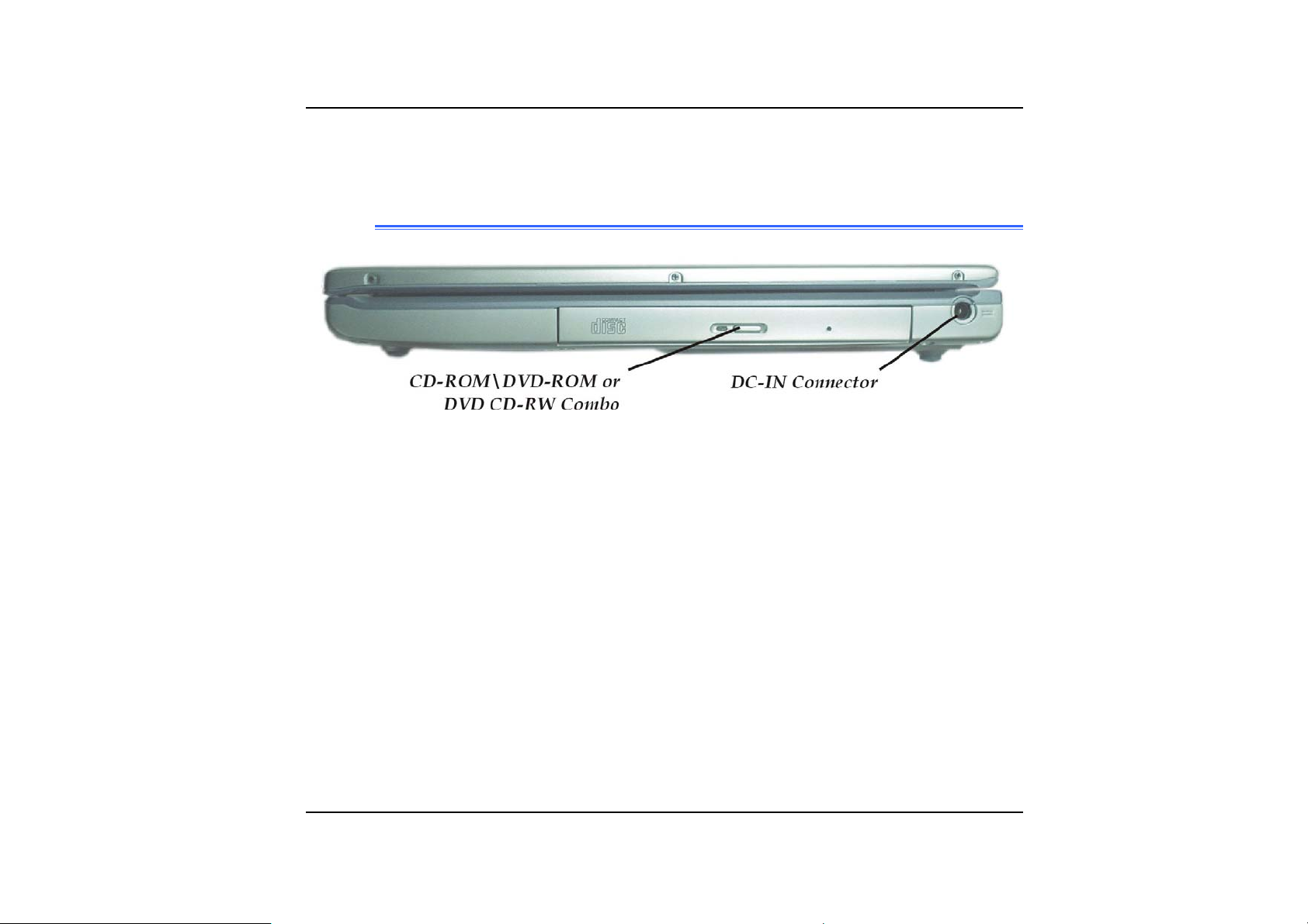
TThhee RRiigghhtt SSiiddee
The CD-ROM/DVD-ROM or DVD CD-RW Combo/ DVD -RW(TM5800)
(Option)
Your Mobile PC comes with a swappable 24X (or higher) 5.25" IDE CD-ROM or 8X
DVD-ROM.
DC IN Connector
Plug the AC adapter into this connector.
- 11 -
Page 26
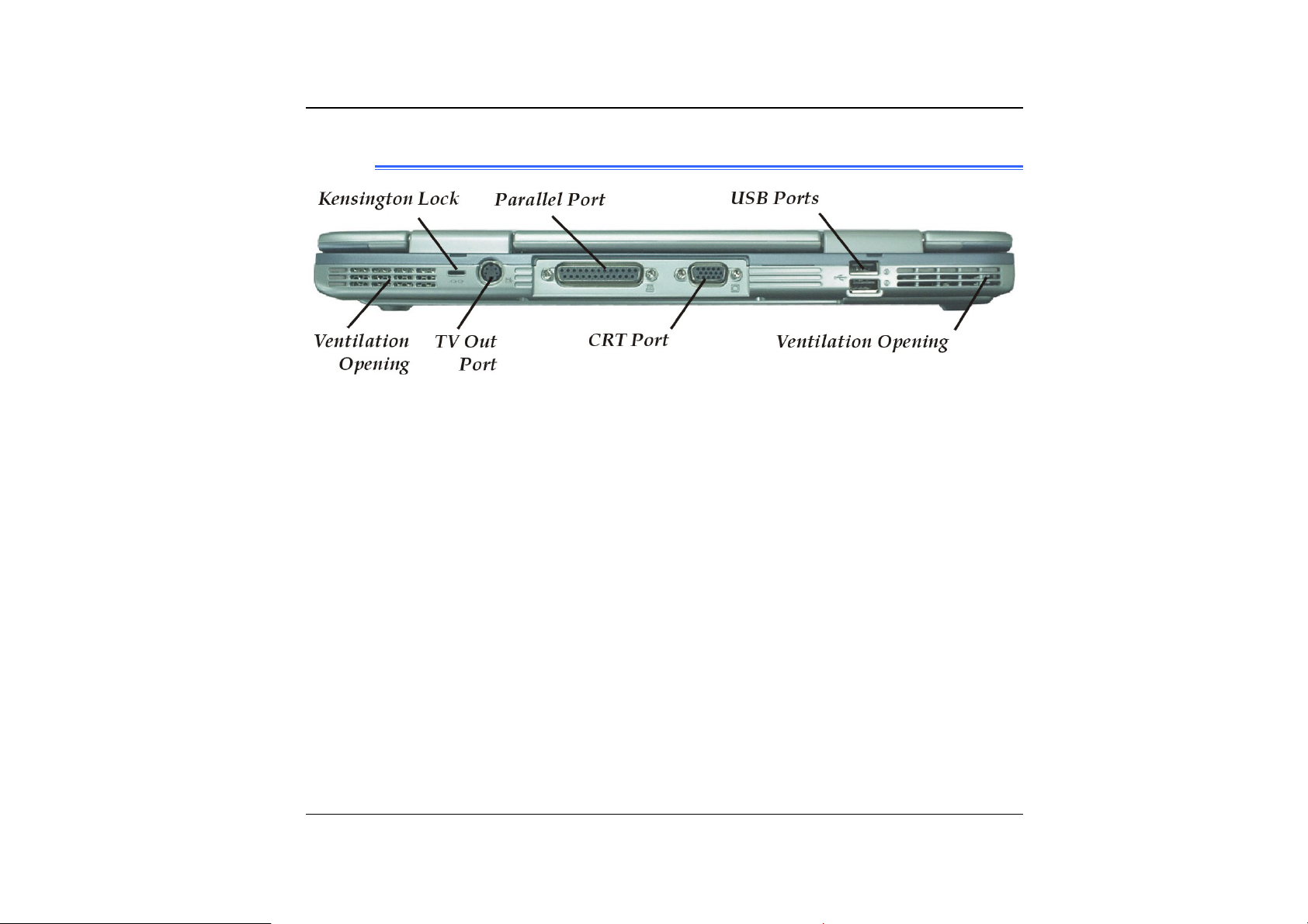
TThhee RReeaarr
Ventilation Opening
Please don't block this opening during operation of the system.
Kensington Lock
Allows you to connect a special computer lock to secure your system.
You can purchase a lock at most computer retailers.
TV Out Port
This 4-pin S-Video port allows you to view the Notebook's Video output on a
television monitor.
12
Parallel Port
This port allows you to easily connect a parallel printer or plotter using this 25-pin bidirectional female port.
External CRT Port
This port allows you to easily connect an external VGA/SVGA display monitor into
your Mobile PC using the 15-pin female connector.
Page 27

USB Ports
Your computer includes two Universal Serial Bus (USB) port. USB is the latest
development in Plug and Play technology.
It will eventually replace the need for separate connectors for external keyboards,
serial ports, and parallel (printer) port.
Ventilation Opening
Please don't block this opening during operation of the system.
- 13 -
Page 28

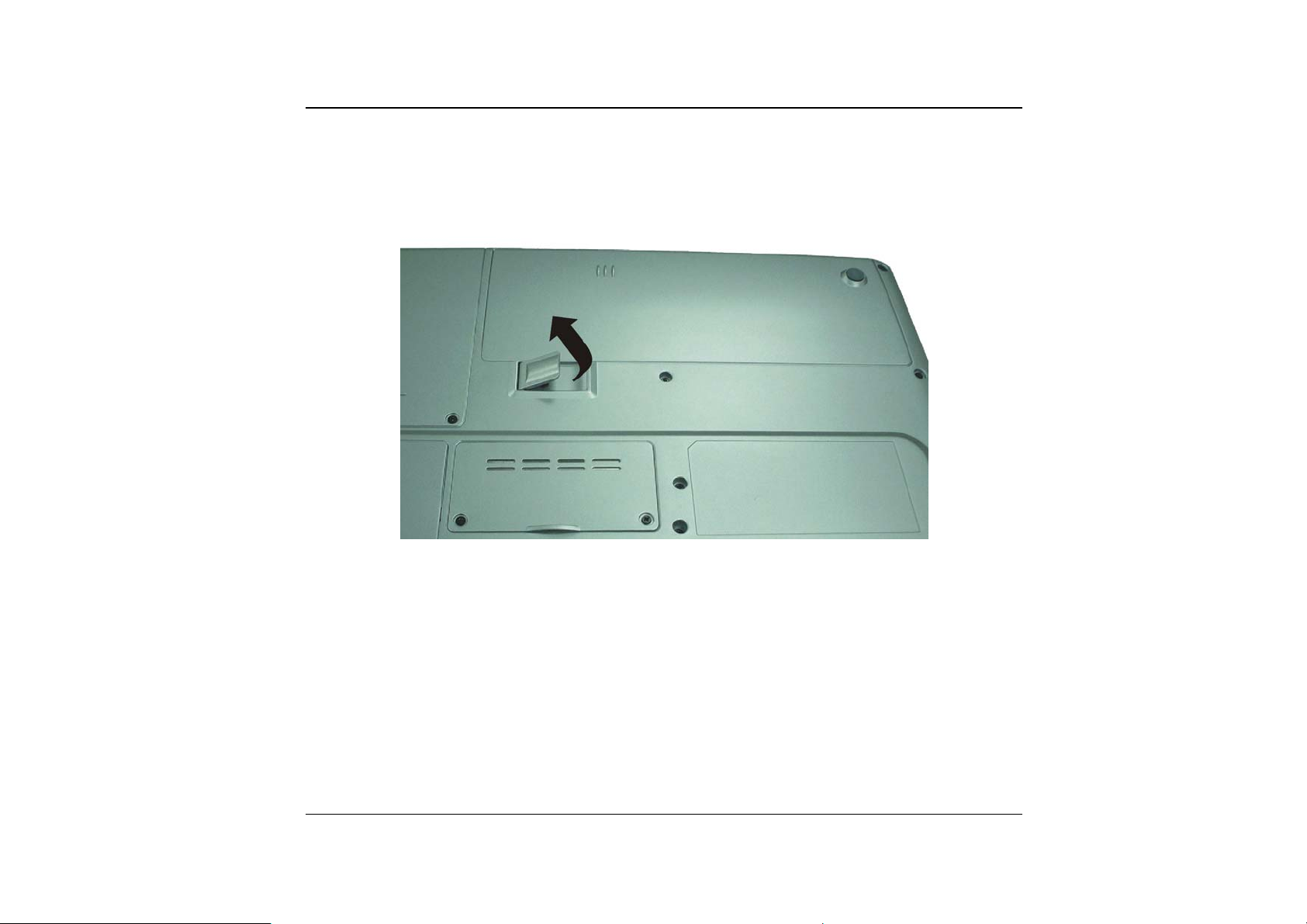
TThhee BBoottttoomm PPaanneell
14
Expansion Compartment
This compartment will serve as an expansion to upgrade your RAM module.
Page 29

Battery Release Latch
Lift up this latch to release the battery from its bay.
Hard Disk Drive
Your computer includes a 2.5-inch IDE hard disk drive (9.5mm in height). The
Mobile PC's BIOS automatically detects IDE drive types.
Battery Compartment
Your Mobile PC comes equipped with a factory-installed battery pack module. After
the battery runs down, the module can be removed and replaced with a charged
battery.
- 15 -
Page 30

16
Page 31

Chapter 2
Geettttii
G
ngg
n
Stt
S
arrttee
a
d
d
- 17 -
Page 32

CCoonnnneeccttiinngg ttoo aa PPoowweerr SSoouurrccee
CCoonnnneeccttiinngg tthhee AACC AAddaapptteerr
A universal AC adapter is
provided to supply your computer
with power and also charge the
computer’s battery pack.
The adapter’s AC input voltage
can range anywhere from 100 to
240 volts, covering the standard
voltages available in almost every
country.
The power cord for the AC
adapter requires a three-hole
grounded AC outlet. To connect
the computer to an external power
source:
18
Plug the AC adapter’s connector into the DC-IN connector on the rear of the
11..
computer.
Connect the power cord to the AC adapter and then to a wall outlet.
22..
Page 33

The best kind of AC power source to connect your Mobile PC
to is a UPS (Uninterruptible Power Supply). Lacking this, use a power
strip with a built-in surge protector. Do not use inferior extension cords
as this may result in damage to your Mobile PC. The Mobile PC comes
with its own AC adapter. Do not use a different adapter to power the
computer and other electrical devices.
Whenever possible, keep the AC adapter plugged into the Mobile PC and an
electrical outlet to recharge the battery.
Never turn off or reset your Mobile PC while the hard disk is
in use and the HDD status icon is lit; doing so can result in loss or
destruction of your data. Always wait at least 5 seconds after turning off
your Mobile PC before turning it back on; turning the power on and off in
rapid succession can damage the Mobile PC’s electrical circuitry.
TTuurrnniinngg OOnn YYoouurr MMoobbiillee PPCC
Turn on your Mobile PC by pressing the power button. Hold the button down for a
second or two and release. The Power-On Self Test (POST) runs automatically.
After the POST is completed, the computer reads the operating system from the
hard disk drive into computer memory (this is commonly referred to as “booting” a
computer). If your OS (Operating System such as Windows ME, Windows 2000….
etc) is installed, it should start automatically.
- 19 -
Page 34

To turn the Mobile PC off, save your work and close all open applications, click on
Start, then Shu
press the power button for 4-6 seconds.
t Down and select Shut down the computer and click "Yes" or
OOppeerraattiinngg oonn RReemmoovvaabbllee BBaatttteerryy PPoowweerr
The system provides you with a removable battery pack that
does not provides the computer with information about its power status.
Your computer comes with a rechargeable removable battery pack that lets you
operate the computer without an external power source. When the removable
battery pack is fully charged, you can operate the computer for approximately 2
hours under the following conditions:
• The removable battery pack initially has a full charge.
• No peripheral devices are installed.
• The disk/CD-ROM drives run no more than 10% of the time.
Only use batteries that are approved by an authorized
dealer. All batteries are not the same and therefore should not be treated
as such. Using the wrong battery could cause serious damage to your
computer and yourself through toxic emissions.
20
Page 35

IInnsseerrttiinngg aanndd RReemmoovviinngg tthhee RReemmoovvaabbllee BBaatttteerryy PPaacckk
The removable battery pack should already be inserted in your Mobile PC when
you unpack it. If not inserted, follow these directions:
Turn over the Mobile PC with the front of the unit facing you and place it on a
11..
solid, flat surface.
Angle the battery into the bay. The front edge of the battery should slide into
22..
the grooves in the system case.
Gently lower the battery into the bay and push it until it clicks securely in the
33..
bay.
- 21 -
Page 36
To remove the removable battery pack:
Turn off the Mobile PC, and disconnect the AC adapter.
11..
Close the LCD panel and turn it over and place it on a solid, flat surface.
22..
22
Lift the release latch to release the battery from the bay. At this time the
33..
battery will now be angled slightly out of the bay.
Hold the removable battery at the finger grip and lift it out of the compartment.
44..
Page 37

CChhaarrggiinngg tthhee RReemmoovvaabbllee BBaatttteerryy PPaacckk
The installed removable battery pack charges automatically any time the
computer is connected to the AC adapter and an external power source.
It is a good idea to occasionally discharge the battery pack fully to preserve its
operating performance.
- 23 -
Page 38

Chapter 3
Ussii
U
24
ngg tt
n
hee
h
M
M
obbiillee
o
P
P
C
C
Page 39

AAddjjuussttiinngg tthhee LLCCDD SSccrreeeenn DDiissppllaayy
The LCD screen display can be adjusted by the following key combinations.
KEYS FUNCTIONS
[Fn] + [F7] Decreases the brightness level.
[Fn] + [F8] Increases the brightness level.
[Fn] + [F12] This key combination toggles the display between the LCD, CRT,
simultaneous LCD/CRT.
LLCCDD CCaarree
LCD screens are delicate devices that need careful handling. Please pay
attention to the following precautions:
• When you are not using the computer, keep the LCD screen closed to
protect it from dust.
• If you need to clean your LCD screen, use a soft tissue to gently wipe the
LCD surface.
• Do not put your fingers or sharp objects directly on the surface and never
spray cleaner directly onto the display.
• Do not press on, or store any objects on the cover when it is closed. Doing
so may cause the LCD to break.
EExxtteerrnnaall CCRRTT DDiissppllaayy
You can hook up an external monitor through the 15-pin CRT connector. Three
configurations are available:
For TM5600
• LCD only
• CRT only
- 25 -
Page 40

• TV only
For TM5800
• LCD only
• CRT only
• LCD & CRT mirror mode
• LCD & TV mirror
• TV only
You can switch between these display configurations by pressing the key
combination [Fn] + [F12].
• TV only
To shift the display screen from your computer to the TV
screen, you will have to utilize the VGA utility function by executing the
VGA Display function. Please refer to Chapter Six on the topic of “VGA
Utilities” section.
For information on connecting an external display, please refer to Chapter Four.
AA TToouurr ooff tthhee MMoobbiillee PPCC’’ss KKeeyybbooaarrdd
The Mobile PC’s keyboard uses a standard QWERTY layout with the addition of
special function keys and an embedded numeric keypad for number intensive data
entry. Your keyboard supports Windows by incorporating the two Windows
specific keys. With the two Windows keys you will be able to access and take
advantage of many of the timesaving features of Windows software.
The function keys (F1-F12) on the top row of the keyboard, serve different
26
Page 41

purposes and carry out different tasks depending on the application you are
running.
The cursor (arrow) keys (which are all located in the lower right corner of your
keyboard) and the [PgUp], [PgDn], [Home] and [End] keys (which are located
along the right edge of the keyboard) allow you to move the active cursor of the
computer to various locations on the screen or within the document.
The embedded numeric keypad consists of 15 keys that make number intensive
input more convenient. Like the [Num Lock] key, these keys are labeled in blue
on the keycaps. Numeric assignments are located at the upper right of each key.
When the numeric keypad is engaged, the NumLock icon will appear in the
System Window. The keypad is activated by pressing the [Fn] + [NumLk] key. If
an external keyboard is connected, pressing the NumLock key on either the
Mobile PC or external keyboard will enable/disable NumLock of both keyboards in
unison.
To disable the Mobile PC numeric keypad while keeping the keypad on an
external keyboard activated, use the [Fn] + [NumLk] hot key on the Mobile PC
keyboard.
- 27 -
Page 42

TThhee MMoobbiillee PPCC’’ss HHoott KKeeyy CCoonnttrroollss
KEYS FUNCTION(S)
Power Button Press this button once to power on or enter the
Internet Button Open Internet WWW Home short-cut key
Email Button Open Email Reader short-cut key
[Fn] + [F2] This key combination turns on/off the volume.
[Fn] + [F3] Decreases the speaker volume.
[Fn] + [F4] Increases the speaker volume.
[Fn] + [F7] Decreases the brightness level.
[Fn] + [F8] Increases the brightness level.
[Fn] + [F12] This key combination toggles the display between the LCD,
TThhee TToouucchhPPaadd
The touchpad is a rectangular electronic panel located just below your keyboard.
You can use the static-sensitive panel of the touchpad and slit it to move the
cursor. You can use the buttons below the touchpad as left and right mouse
buttons.
suspend/resume mode.
Press this button for more than 4 seconds to power off the
system.
CRT, simultaneous LCD/CRT.
28
Page 43
TToouucchhPPaadd PPrreeccaauuttiioonnss
The TouchPad is a pressure sensitive device. Please take note of the following
precautions.
• Make sure the TouchPad does not come into contact with dirt, liquids or
grease.
• Do not touch the TouchPad if your fingers are dirty.
• Do not rest heavy objects on the TouchPad or the TouchPad buttons.
You can use the TouchPad with Microsoft Windows as well as non-Windows
applications.
- 29 -
Page 44

CCoonnnneeccttiinngg aann EExxtteerrnnaall TTrraacckkiinngg DDeevviicceess
The system will only enables you to use one tracking device whether it is an
internal or external tracking device.
DDaattaa SSttoorraaggee aanndd RReettrriieevvaall
Data storage and retrieval are two of the most fundamental tasks you will perform
when working with your computer. The Mobile PC is equipped with a hard disk
drive (HDD). The HDD is removable allowing for easy upgrades.
TThhee CCDD--RROOMM//DDVVDD--RROOMM//CCoommbboo
FFeeaattuurreess ooff tthhee CCDD--RROOMM//DDVVDD--RROOMM//CCoommbboo MMoodduullee
The features of the CD-ROM/DVD-ROM/Combo drive are listed below.
• The Audio Play feature allows you to play music CDs
• Front panel load/unload button
• Supports CD-DA, CD-ROM mode 1 and mode 2, Multi-Session Photo CD™,
CD-I/Video CD (pcs.)
• Low power consumption
• 12.7mm height
30
PPrreeccaauuttiioonnss ffoorr HHaannddlliinngg CCDD--RROOMM//DDVVDD--RROOMM//CCoommbboo DDiissccss
• Always hold the disc by the edges, avoid touching the surface.
• Use a clean, dry, cloth to remove dust, smudges, or fingerprints. Wipe from
the center outward.
Page 45

• Do not write or place objects on the surface of the disc.
• Store discs in a cool dry place not to damage the disc.
• Do not use benzene, thinners, or cleaners with detergent. Only use CD-
ROM/DVD-ROM cleaning kits.
• Do not bend or drop the discs.
LLooaaddiinngg aa DDiisscc
To play a CD disc, follow the instructions listed below.
Push the CD-ROM/DVD-ROM/Combo eject button on the CD drive door.
11..
Gently pull the tray all the way out.
Carefully lift the CD-ROM/DVD-ROM/Combo by the edges and make sure the
22..
shiny surface is face down (the side with no writing on it). Carefully insert the
CD-ROM onto the tray. Push the CD-ROM/DVD-ROM down gently so that it
snaps onto the center ring.
Push the tray back into the drive.
33..
To remove a disk, do the following:
Check the LED display and make sure that the computer is not accessing the
11..
CD-ROM/DVD-ROM drive.
Push the eject button and pull the tray all the way out.
22..
Carefully pick up the CD disk by the edges and – while pressing down on the
33..
center ring – remove the CD-ROM/DVD-ROM/Combo from the tray.
Do not insert any foreign objects into the disc tray. If you
- 31 -
Page 46

experience difficulty when ejecting the CD disk tray, stretch a paper clip
(or use a pin or a thin metal rod) and insert it into the emergency eject hole
located on the right side of the front panel. The CD disk tray should eject
immediately. This procedure can also be used to remove a CD from the
drive when the Mobile PC is powered off.
RReemmoovviinngg tthhee DDVVDD--RROOMM//CCoommbboo DDrriivvee
Remove the screws and push the drive into the direction of the arrow as
11..
described in the illustration.
32
Page 47

Pull out the DVD-ROM drive from the bay.
22..
PPoowweerr SSaavviinngg MMooddeess
This section contains information on the Mobile PC’s power system, including the
AC Adapter, the battery system, recharging the battery, and tips for conserving
battery power.
The power system is comprised of two parts, the AC Adapter and the battery
system. The AC Adapter converts AC power from a wall outlet to the DC power
required by the computer.
TThhee BBaatttteerryy PPoowweerr SSyysstteemm
A fully charged pack will provide approximately 2 hours of battery life depending
on your system configuration application it runs.
Charging the battery takes about 3 hours to charge when the system is in off state.
If possible, always charge the battery completely.
RReemmoovviinngg tthhee RReemmoovvaabbllee BBaatttteerryy PPaacckk
To remove the battery pack from its compartment, please refer to Chapter Two,
Inserting and Removing the Removable Battery Pack.
To calibrate the battery pack follows the instructions below:
Insert the removable battery into the battery compartment and turn on the
11..
Mobile PC. If the removable battery is completely without power go to the
next step.
Otherwise, let the removable battery run down until the battery low-low
warning beeps are heard.
- 33 -
Page 48

Turn the Mobile PC off. Connect the AC adapter and let the removable
22..
battery fully recharge. When the removable battery charge indicator turns off,
the battery is fully charged.
Turn On the Mobile PC, let the removable battery run down until the battery is
33..
in low-low state and you hear a warning beeps. You can now connect the AC
adapter.
The removable battery pack is now calibrated properly.
44..
In general, using the removable battery until the low-low battery-warning indicator
appears and fully recharges the battery each time (full discharge/charge cycle) will
ensure the accurate reporting of the battery gauge status.
34
AAuuttoommaattiicc RReemmoovvaabbllee BBaatttteerryy PPaacckk CChhaarrggiinngg FFuunnccttiioonn
You can automatically charge the removable battery pack by using the AC
Adapter. The charge time is about three hours when the Mobile PC power is
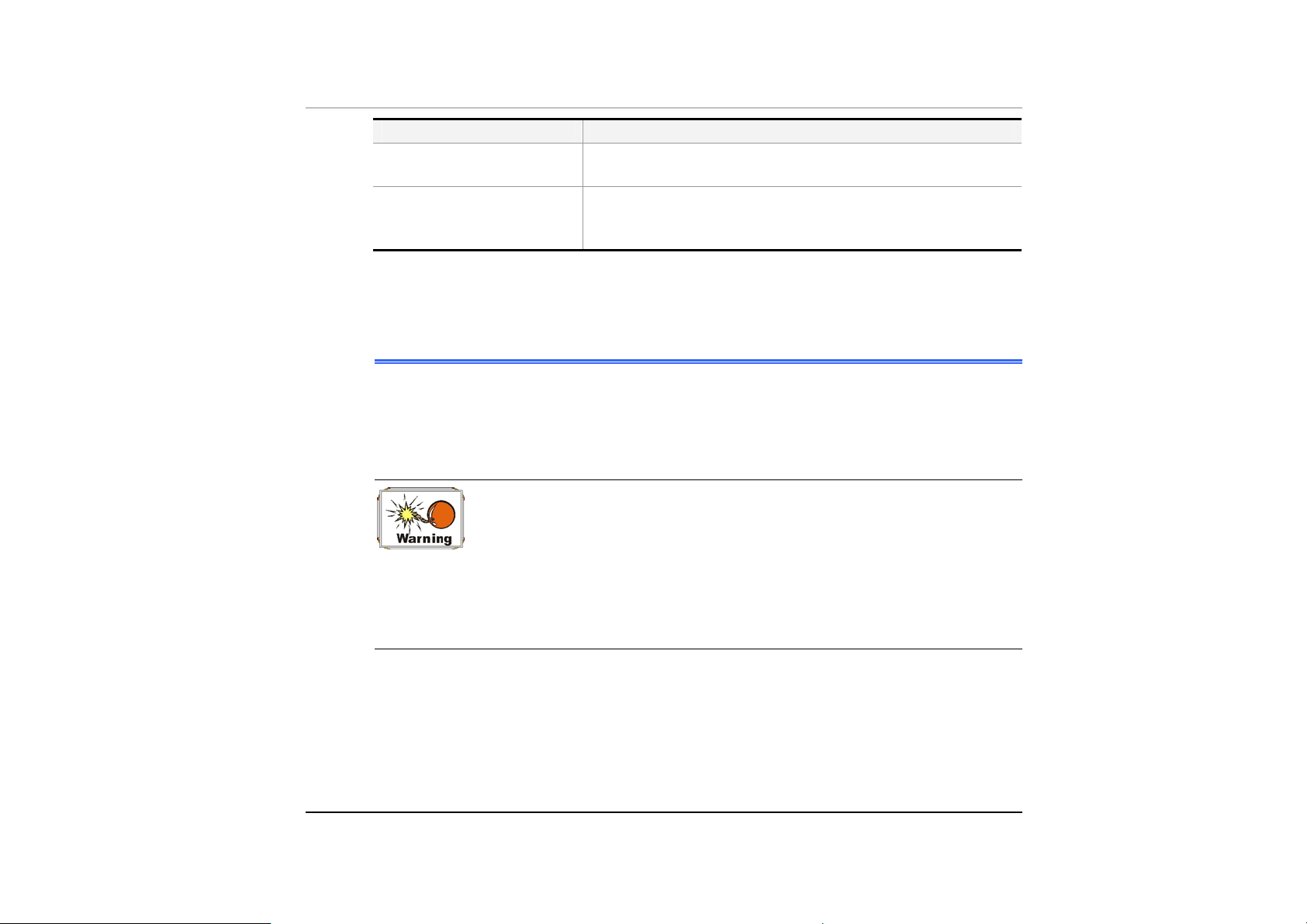
turned off. The following table summarizes the charging modes:
Charge Mode Charge Time
Fast Approximately 3 hours with the system off or in Suspend mode.
The temperature must be 25°C or below room temperature.
BBaatttteerryy LLooww WWaarrnniinngg
When the removable battery pack initially reaches the “Battery Low” state
approximately 5 ~ 6 minutes of the usable battery life is left.
You will hear an audible beep signal every 1.5 seconds alerting you to the
“Battery Low” status. When the battery power reaches the “Battery Low Low”
status the beeping sound will accelerate.
Your battery now has 1 ~ 2 minutes of battery charge remaining. You must save
your data or connect AC power immediately; otherwise, you may lose your data.
Page 49
Sound Meaning
Continuous beeping
every 1 seconds
Beeping accelerates Battery Low Low: Indicates that there is 1 to 2
When there is only one minute of battery charge remaining, the Mobile PC will
suspend to the HDD and power off. You should connect AC power and resume to
save your work.
Battery Low: Indicates that there is 5 to 6 minutes
charge remaining.
minutes of battery charge remaining. Save your work
and turn off the Mobile PC, or connect the AC adapter.
SSmmaallll BBaatttteerryy ffoorr tthhee RReeaall TTiimmee CClloocckk
There is a small built-in battery pack that supplies power to the system in order to
maintain certain system information while the power is off. If the Mobile PC is left
without a power source for long period of time, this battery will be exhausted and
system information will be lost.
Danger of explosion if battery is incorrectly replaced. Replace
only with the same or equivalent type recommended by the manufacturer.
Dispose of used batteries according to the manufacturer's instructions.
Never remove the battery pack while the power is on as this may result in
data loss when the system loses power.
- 35 -
Page 50

RReesseettttiinngg tthhee SSyysstteemm
After installing a software application package, you may be prompted to reset the
system to load the changed operating environment. To reset the system, or
“reboot,” press the [Ctrl] + [Alt] + [Delete] keys simultaneously. This is known
as “warm boot.” This key combination acts as “software” reset switch when you
encounter hardware or software problems, which lock up the Mobile PC.
If this key combination does not shut down the Mobile PC, you can reset the
Mobile PC by using the Mobile PC’s power button. Should the Mobile PC lock up
for some reason, pressing this button powers the Mobile PC off.
AAddjjuussttiinngg tthhee BBrriigghhttnneessss
To adjust the brightness on the LCD screen, press and hold down the [Fn] key in
the lower left hand corner of the keyboard and press the [F7] key to reduce the
brightness or [F8] to increase the brightness.
36
Page 51

Chapter 4
Moobbiillee
M
P
P
C
C
Oppeerraattiioonn
O
- 37 -
Page 52

Your Mobile PC is capable of providing you with efficient and productive mobile
computing, it also has the speed and capacity to service as a desktop system.
This chapter discusses those functions of your Mobile PC that are typical of
desktop systems.
AAuuddiioo
TThhee MMuullttiimmeeddiiaa SSoouunndd SSyysstteemm
The Mobile PC’s built-in audio capabilities allow you to take advantage of a wide
range of education and entertainment multimedia software. The Mobile PC is
equipped with two internal stereo speakers, a microphone, and input audio ports
for external audio units.
An external microphone can be connected to the microphone jack. External
speakers or headphones can be connected to the Mobile PC’s audio-out jack.
External audio devices can be connected to the Line in jack. All audio features
are software controlled. The Mobile PC’s multimedia sound system includes the
following features:
• Supports Windows Sound System compatibility
• Full Duplex operation
• Dynamic filtering reduces noise and distortion rate
• 16-bit digitized audio playback
• A built-in microphone for convenient recording
• Two built-in stereo speakers
• Digitized audio recording through the Mobile PC’s built-in microphone or
any external source
38
Page 53

AAuuddiioo VVoolluummee CCoonnttrrooll
The Mobile PC is equipped with hot-key volume controls: Pressing the [Fn] + [F3]
hot-key combination decreases the audio output volume, press the [Fn] + [F4]
hot-key combination increases the audio output volume.
AAuuddiioo SSooffttwwaarree
Your Mobile PC comes equipped with an integrated sound system capable of
providing you with quality audio sound through the built-in speakers or through
external speakers connected via the system ports.
SSoouunndd RReeccoorrddiinngg
Your system allows you to record sounds and store them as files using the
microphone via the microphone jack on the rear of the Mobile PC. Check the
Windows Help and Support Center in Windows for information on using the
various elements in sound recording.
For a high-quality sound, click on the "Volume Control" at the
lower right end of your screen. From the Volume Control windows, click
on the "Advanced" tab, click and select the "Microphone Boost" item.
PPllaayyiinngg SSoouunndd FFiilleess
Your Mobile PC can play audio files stored in MIDI, WAVE or MP3 file format.
Check the Help and Support Center in Windows for information on the functions of
the Media Player.
- 39 -
Page 54

EExxtteerrnnaall SSppeeaakkeerrss aanndd MMiiccrroopphhoonnee
The sound system is capable in providing high-quality sound to external speakers
and receiving and processing sounds from an external microphone or external
sound source.
CCoonnnneeccttiinngg PPeerriipphheerraall DDeevviicceess
To expand your computing capabilities, you can add a variety of external devices
to your computer. You may, for example, want to add a mouse, modem, or a
printer.
Connect peripheral devices to the computer's interface ports as shown below:
40
Page 55

- 41 -
Page 56

R
R
u
u
n
n
nii
n
ngg
n
BII
B
O
O
S
S
Seett
S
Chapter 5
u
p
u
p
42
Page 57

IInnttrroodduuccttiioonn
The BIOS (Basic Input and Output System) Setup program is a menu driven utility
that enables you to make changes to the system configuration and tailor your
system to reflect installed hardware or alter system performance. When the
Mobile PC is turned back on, the system is configured with the values stored in
CMOS.
NNaavviiggaattiinngg tthhrroouugghh BBIIOOSS SSeettuupp
The Setup program has been designed to make it as easy to use as possible. If
you accidentally make a setting and don’t know which one to switch back to, the
Setup program has a hot key that allows you to return to the previous value.
AAcccceessssiinngg tthhee BBIIOOSS SSeettuupp PPrrooggrraamm
To access the BIOS Setup program, press the DEL key after the Mobile PC has
run through its POST.
IItteemm SSppeecciiffiicc HHeellpp
On the right side of the Setup screen is an area labeled Item Specific Help. This
area will list navigation key shortcuts and information that is specific for the item
that you are currently editing.
TThhee MMeennuu BBaarr
The top of the screen has a menu bar with the following selections:
- 43 -
Page 58

SSttaannddaarrdd CCMMOOSS SSeettuupp
Set the time and date. Configure disk drives.
AAddvvaanncceedd CCMMOOSS SSeettuupp
Configure basic system performance parameters.
PPeerriipphheerraall SSeettuupp
Configure I/O support for the Mobile PC.
To access the menu bar items, press the up or down arrow key on the
keyboard until the desired item is highlighted.
TThhee LLeeggeenndd BBaarr
At the bottom of the Setup screen you will notice a legend bar. The keys in the
legend bar allow you to navigate through the various setup menus.
The following table lists the keys found in the legend bar with their corresponding
alternates and functions.
Legend Key
Esc Jumps to the Exit menu or returns to the Main menu from a
↑ or ↓
PgUp/PgDn Set to modify the field selected.
F2/F3 Set the color (8 colors) of the BIOS Setup screen.
F10 Save and Exit.
Enter Will select a sub menu or show a range of options for a field.
Function
submenu.
Moves the cursor up and down between fields.
44
Page 59

LLaauunncchhiinngg SSuubbmmeennuuss
Note that a right pointer symbol ` appears to the left of certain fields. This pointer
indicates that a submenu can be launched from this field. A submenu contains
additional options for a field parameter. To call up a submenu, simply move the
cursor to highlight the field and press the [Enter] key. Use the [Esc] key to return
to the Main menu.
GGeenneerraall HHeellpp
In addition to the Item Specific Help window, the BIOS Setup program also
provides a General Help screen can be called up from any menu by simply
pressing [F1] key.
Use the up and down arrow keys (↑↓) to scroll through the entire help document.
Press the Home key to display the first page, press End to go to the last page. To
exit the help window, press the [Esc] key.
SSaavvee CChhaannggeess aanndd EExxiitt tthhee SSeettuupp PPrrooggrraamm
Refer to the Exit menu section of this chapter for detailed information on saving
changes and exiting the setup program.
- 45 -
Page 60

TThhee SSttaannddaarrdd CCMMOOSS SSeettuupp
When the Setup program is accessed, the following screen appears:
46
DDaattee//TTiimmee
The current values for each category are displayed. Enter new values through the
keyboard “PgUp/PgDn” keys.
PPrrii MMaasstteerr,, SSeecc MMaasstteerr
Page 61

Select one of these hard disk drive icons to configure the hard disk drive named in
the option.
TThhee AAddvvaanncceedd CCMMOOSS SSeettuupp
When the Setup program is accessed, the following screen appears:
QQuuiicckk BBoooott
Set this option to Enabled to instruct AMI BIOS to boot quickly when the
computer is powered on.
- 47 -
Page 62

The settings are Disabled or Enabled (default value)
t
sst
1
1
BBoooott DDeevviiccee
This option sets the type of device for the first boot drives that the
AMIBIOS attempts to boot from after AMIBIOS POST completes.
The settings are Disabled (default value), HDD, CD-ROM and
USB FDD.
BBoooot
t
DDeevviiccee
nndd
2
2
This option sets the type of device for the second boot drives that
AMIBIOS attempts to boot from after AMIBIOS POST completes.
The settings are Disabled, HDD, CD/DVD (default value) and
USB FDD.
d
rrd
3
3
BBoooott DDeevviiccee
This option sets the type of device for the third boot drives that the
AMIBOOS attempts to boot from after AMIBIOS POST completes.
The settings are Disabled, IDE-0(default value), CD/DVD.
48
SS..MM..AA..RR..TT.. ffoorr HHaarrdd DDiisskkss
Set this option to Enabled to permit AMIBIOS to use the SMART (System
Management System and Reporting Technologies) protocol for reporting
server system information over a network.
The settings are Enabled or Disabled (default value).
PPaasssswwoorrdd CChheecckk
This option enables password checking every time the system boots or
when you run AMIBIOS Setup. If Always is chosen, a user password
prompt appears every time the computer is turned on. If Setup is chosen,
Page 63

the password prompt appears if AMIBIOS is executed.
The settings are Setup (default value), Always.
UUSSBB FFuunnccttiioonn
Set this option to enabled or disabled the USB device of your system.
The settings are Enabled (default value) or Disabled.
UUSSBB DDeevviiccee LLeeggaaccyy SSuuppppoorrtt
Set this option to enable support for all USB devices if the USB
Function option is set to Enabled.
The settings are Disabled (default value), No Mice or All Device.
Please take note that before you installing the Windows
98SE/ME, be sure to disable the “USB Device Legacy Support” item in the
Advanced CMOS Setup category of your system BIOS Setup.
BBeeeepp OOnn BBoooott
Set this option to enable or disable the beeping sound when the system
start to boot.
The settings are Disabled (default value), Enabled
- 49 -
Page 64

TThhee PPeerriipphheerraall SSeettuupp
50
OOnnBBooaarrdd PPaarraalllleell PPoorrtt
This option specifies the base I/O port address of the parallel port on the
motherboard.
The settings are Auto (default value), Disabled, 378h, 278h, or
3BCh.
Parallel Port Mode
Page 65

This option specifies the parallel port mode.
TThhee sseettttiinnggss aarree NNoorrmmaall,, BBii--ddiirr,, EEPPPP oorr EEPPPP++EECCPP
e
d
e
ffaauulltt vvaalluuee))..
((d
EPP Version
This option specifies the parallel port mode value.
TThhee sseettttiinnggss aarree 11..77 ((ddeeffaauulltt vvaalluuee)) oorr 11..99..
PPaarraalllleell PPoorrtt IIRRQQ
This is only a display-only item and cannot be altered.
PPaarraalllleell PPoorrtt DDMMAA CChhaannnneell
This is only a display-only item and cannot be altered.
CChhaannggee SSuuppeerrvviissoorr PPaasssswwoorrdd
This field allows you to set the Supervisor password. To set the Supervisor
password, highlight this field and press the [Enter] key. The following dialog box
appears:
Enter new supervisor password:
AAuuttoo CCoonnffiigguurraattiioonn wwiitthh OOppttiimmaall SSeettttiinnggss
The optimal default settings are best-case values that should optimize system
performance. To set the configuration, highlight this field and press the [Enter]
key. The following dialog box appears:
- 51 -
Page 66

Load high performance settings [Y/N] ?
SSaavvee SSeettttiinnggss aanndd EExxiitt
This option saves your selections and exit the Setup program.
Save current settings and exit [Y/N] ?
EExxiitt WWiitthhoouutt SSaavviinngg
This option should only be used if you do not want to save the changes you have
made to the Setup program.
Quit without saving [Y/N] ?
52
Page 67

T
T
hee
h
S
S
offtt
o
w
w
Chapter 6
arree
a
Uttiilliittiieess
U
Diiss
D
kss
k
- 53 -
Page 68

UUSSEERR''SS IINNFFOO::
the driver: AutoRun installation and Manual installation.
There are two separate procedures on how to install
AAuuttooRRuunn IInnssttaallllaattiioonn
• Follow the step-by-step procedures on the CD-ROM/DVD-ROM to execute
the “AutoRun” application by selecting the topic of “Driver Installation”.
• To re-run the “AutoRun” installation, please refer to the procedures on the
“Manual Installation” for a more detailed explanation.
IInnssttaalllliinngg VVGGAA DDiissppllaayy DDrriivveerrss ffoorr WWiinn9988//22KK//MMEE//XXPP
This section describes the operation and installation of VGA display software
drivers supplied on the Driver Utility CD-ROM that is shipped with your computer.
Insert the CD-ROM Driver into your CD-ROM/DVD-ROM drive.
11..
Click “Start” and Select “Run”.
22..
Type the following:
33..
D:\VGA\TM5800\Xinst.exe
54
D:\VGA\TM5600\Xinst.exe
(If D is not your CD-ROM/DVD-ROM drive, substitute D with the correct drive
letter).
Click on “Utility and Driver Setup” to begin the Installation Wizard.
44..
Follow the Wizard’s on-screen instructions to complete the installation.
55..
Restart the system.
66..
Page 69

IInnttaalllliinngg tthhee AAuuddiioo DDrriivveerr ffoorr WWiinn9988//22KK//MMee//XXPP
To install the audio driver you must first remove the currently installed driver.
Insert the CD-ROM Driver into your CD-ROM/DVD-ROM drive.
11..
Click “Start” and Select “Run”.
22..
Type the following: D:\Audio\Setup.exe (If D is not your CD-ROM/DVD-ROM
33..
drive, substitute D with the correct drive letter).
Click on “Setup” to begin the Installation Wizard.
44..
Follow the Wizard’s on-screen instructions to complete the installation.
55..
Restart the system.
66..
IInnttaalllliinngg tthhee LLAANN DDrriivveerr ffoorr WWiinn9988//22KK//MMee//XXPP
To install the LAN driver you must first remove the currently installed driver.
Insert the CD-ROM Driver into your CD-ROM/DVD-ROM drive.
11..
Click “Start” and Select “Run”.
22..
Type the following: D:\LAN\Setup.exe (If D is not your CD-ROM/DVD-ROM
33..
drive, substitute D with the correct drive letter).
Click on “Setup” to begin the Installation Wizard.
44..
Follow the Wizard’s on-screen instructions to complete the installation.
55..
Restart the system.
66..
- 55 -
Page 70

IInnssttaalllliinngg tthhee TToouucchhPPaadd DDrriivveerr ffoorr WWiinn9988//22KK//MMee//XXPP
To install the touchpad driver you must first remove the currently installed driver.
Insert the CD-ROM Driver into your CD-ROM/DVD-ROM drive. Click “Start”
11..
and Select “Run”.
Type the following:
22..
D:\Utility\Touchpad\Win2K&XP\Setup.exe or
D:\ Utility \Touchpad\Win98&ME\Setup.exe (If D is not your CD-ROM/DVDROM drive, substitute D with the correct drive letter).
Click on “Setup” to begin the Installation Wizard. Follow the Wizard’s on-
33..
screen instructions to complete the installation.
Restart the system.
44..
IInnssttaalllliinngg tthhee UUSSBB2200 DDrriivveerr ffoorr WWiinn22KK//XXPP
To install the USB20 driver you must first remove the currently installed driver.
Insert the CD-ROM Driver into your CD-ROM/DVD-ROM drive. Click “Start”
11..
and Select “Run”.
Type the following:
22..
D:\USB\TM5800\Setup.exe
56
D:\USB\TM5600\Setup.exe
(If D is not your CD-ROM/DVD-ROM drive, substitute D with the correct drive
letter).
Click on “USB20” to begin the Installation Wizard. Follow the Wizard’s on-
33..
screen instructions to complete the installation.
Restart the system.
44..
Page 71

IInnssttaalllliinngg tthhee HHoottkkeeyy DDrriivveerr ffoorr WWiinn9988 oonnllyy
To install the Hotkey driver you must first remove the currently installed driver.
Insert the CD-ROM Driver into your CD-ROM/DVD-ROM drive. Click “Start”
11..
and Select “Run”.
Type the following:
22..
D:\Hotkey\Win98\Setup.exe (If D is not your CD-ROM/DVD-ROM drive,
substitute D with the correct drive letter).
Click on “Setup” to begin the Installation Wizard. Follow the Wizard’s on-
33..
screen instructions to complete the installation.
Restart the system.
44..
IInnssttaalllliinngg tthhee WWiirreelleessss LLAANN DDrriivveerr ffoorr WWiinn9988//22KK//MMEE//XXPP
To install the Hotkey driver you must first remove the currently installed driver.
Insert the CD-ROM Driver into your CD-ROM/DVD-ROM drive. Click “Start”
11..
and Select “Run”.
Type the following:
22..
D:\Utility\Wireless LAN\Setup.exe (If D is not your CD-ROM/DVD-ROM drive,
substitute D with the correct drive letter).
Click on “Setup” to begin the Installation Wizard. Follow the Wizard’s on-
33..
screen instructions to complete the installation.
Restart the system.
44..
- 57 -
Page 72

MMaannuuaall IInnssttaallllaattiioonn
To install the driver manually, follow the step-by-step procedures described on
each individual section for a more clear installation.
IInnssttaalllliinngg tthhee MMooddeemm DDrriivveerr ffoorr WWiinnXXPP
Please follow these instructions to install the Modem driver:
From your screen, click on the "My Computer" icon and use your mouse or
11..
touchpad right button to select the "Properties" item.
Click on the "Hardware" tab from the "System Properties" dialog window.
22..
Click on the "Other Device" (denoted by a yellow mark symbol), select the
33..
"PCI Modem" .
Click the "Re-install Driver" tab and select the "Install from a list or specific
44..
location (Advanced)" item.
Select the "Include this location in the search" item.
55..
Select the "Browse" button from the "Include this location in the search" and
66..
specify for the designate location of your CD driver.
58
IInnssttaalllliinngg tthhee MMooddeemm DDrriivveerr ffoorr WWiinn22KK
Please follow these instructions to install the Modem driver:
From your screen, click on the "My Computer" icon and use your mouse or
11..
touchpad right button to select the "Properties" item.
Page 73

Click on the "Hardware" tab from the "System Properties" dialog window.
22..
Select the “PCI Device” in the “Other Devices” group (denoted by a yellow
33..
mark symbol).
Click the "Reinstall Driver" tab and select the "Search for a suitable driver for
44..
my device(recommand)" item.
Select the “Hardware types (Modems)”.
55..
Click on the “Specify a location” and click the "Browse" button and specify for
66..
the designate location of your CD driver.
IInnssttaalllliinngg tthhee MMooddeemm DDrriivveerr ffoorr WWiinn9988SSEE//MMEE
Please follow these instructions to install the Modem driver:
From your screen, click on the "My Computer" icon and use your mouse or
11..
touchpad right button to select the "Properties" item.
Click on the "Device Manager" and select the "PCI Card" item.
22..
Use your mouse cursor to double click the "Reinstall Driver" item.
33..
Select the "Search for a better driver than the one your device is using
44..
now.(recommand)" item and click on the "Specify a location" item.
Select the "Browse" button from the "Include this location in the search" item
55..
and specify for the designate location of your CD driver.
- 59 -
Page 74

VVGGAA UUttiilliittiieess ffoorr WWiinn9988
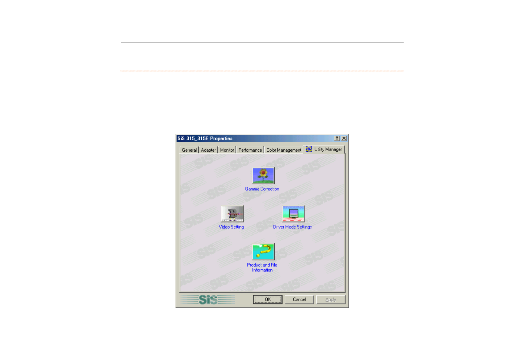
After you have restarted Windows, open the “Control Panel” and double click on
the “Display” icon. From the “Display Properties” window, select the “Settings” tab
and click on the “Advanced” tab to enter the "SiS 315_315E Properties" window.
You will notice three new entries have been made in the Display Properties
window: Gamma Correction, Driver Mode Settings, and Product and File
Information.
60
Page 75

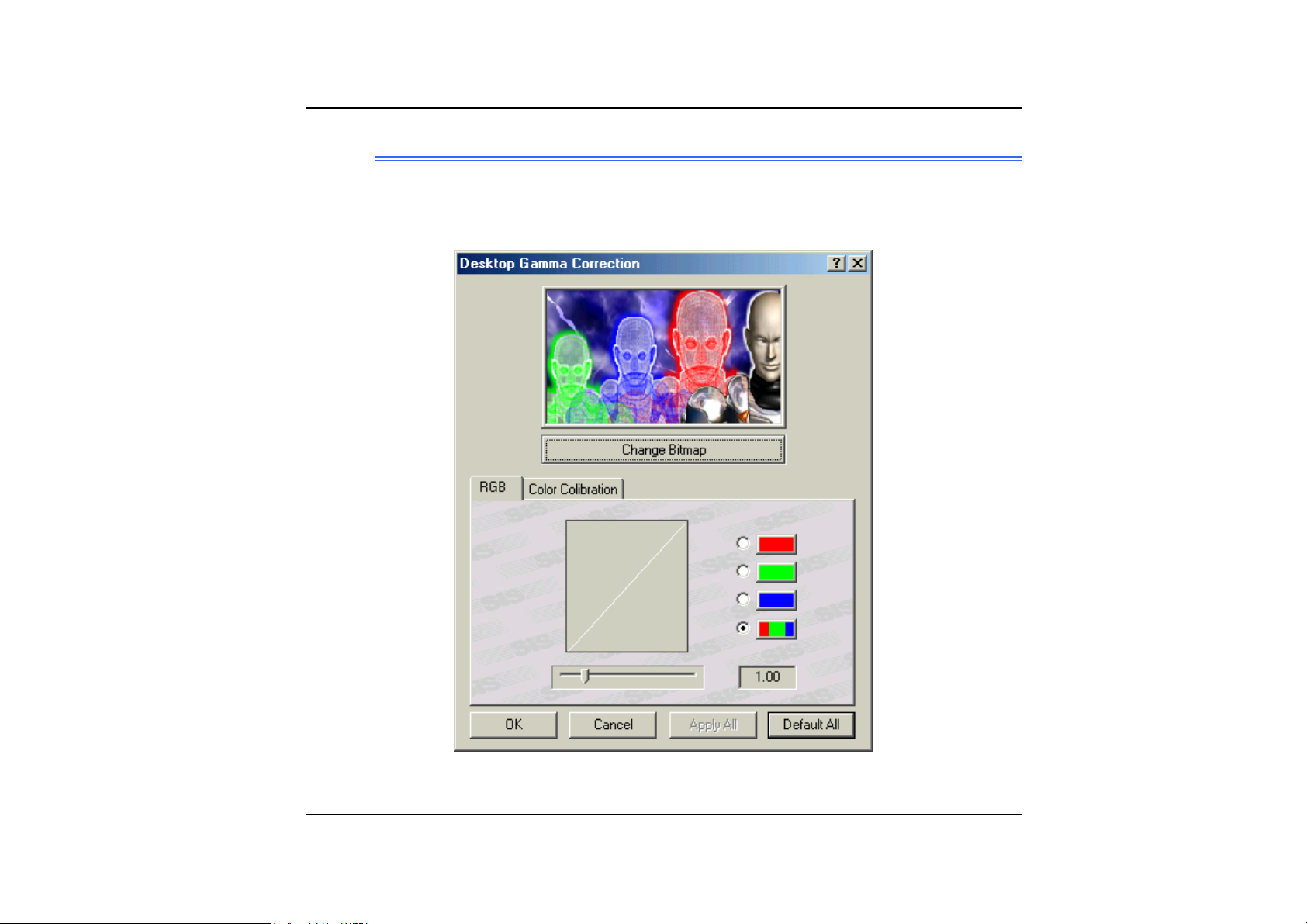
GGaammmmaa CCoorrrreeccttiioonn
You can adjust the right color for your window screen by moving the “Brightness”
adjustment window to increase or decrease the right resolution for your screen
display.
- 61 -
Page 76
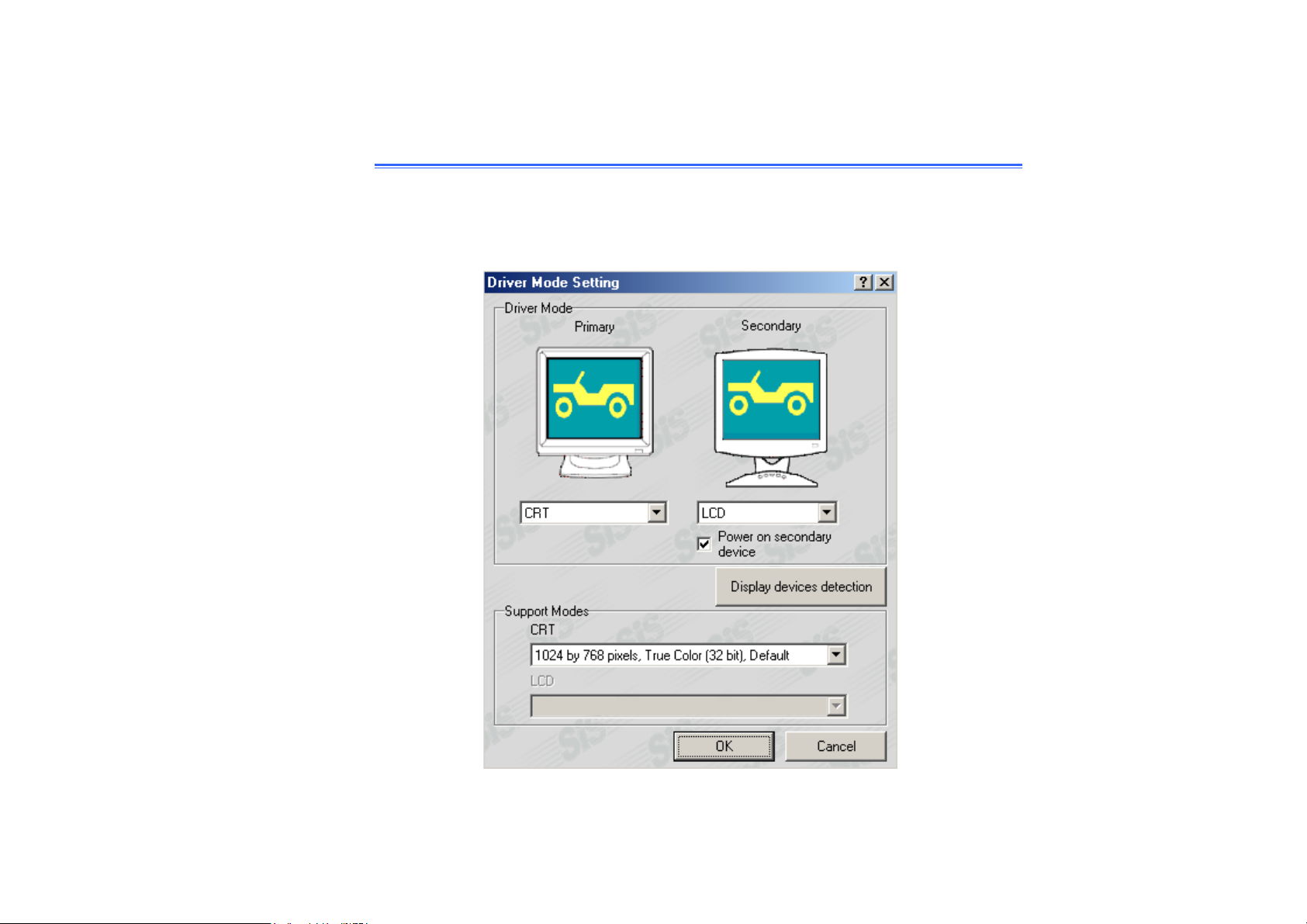
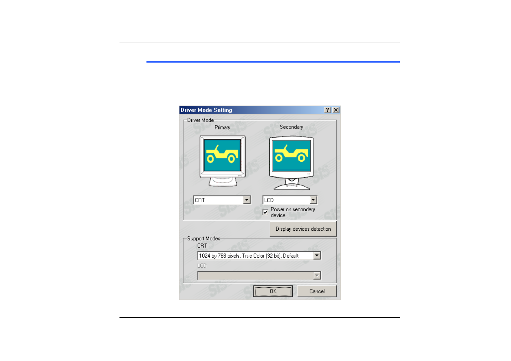
DDrriivveerr MMooddee SSeettttiinngg
The SiS's driver allows three simultaneous outputs to LCD, TV and CRT for
TM5600. And allows five simultaneous outputs to LCD, TV, CRT, LCD & CRT
mirror mode, LCD & TV mirror mode for TM5800. Before proceeding, be sure the
monitor is connected to the computer.
Page 77
VVGGAA UUttiilliittiieess ffoorr WWiinnMMEE//WWiinn22KK
After you have restarted Windows, open the “Control Panel” and double click on
the “Display” icon. From the “Display Properties” window, select the “Settings” tab
and click on the “Advanced” tab to enter the "SiS 315_315E Properties" window.
You will notice three new entries have been made in the Display Properties
window: Gamma Correction, Driver Mode Settings, Video Setting, and Product
and File Information.
- 63 -
Page 78
GGaammmmaa CCoorrrreeccttiioonn
You can adjust the right color for your window screen by moving the “Brightness”
adjustment window to increase or decrease the right resolution for your screen
display.
64
Page 79
DDrriivveerr MMooddee SSeettttiinngg
The SiS's driver allows three simultaneous outputs to LCD, TV and CRT for
TM5600. And allows five simultaneous outputs to LCD, TV, CRT, LCD & CRT
mirror mode, LCD & TV mirror mode for TM5800. Before proceeding, be sure the
monitor is connected to the computer.
- 65 -
Page 80

VViiddeeoo SSeettttiinngg
From the "Setting", you can also adjust the video of your display to overlay,
contrast or brightness.
66
Page 81

VVGGAA UUttiilliittiieess ffoorr WWiinnXXPP
After you have restarted Windows, open the “Control Panel” and double click on
the “Display” icon. From the “Display Properties” window, select the “Settings” tab
and click on the “Advanced” tab to enter the "SiS 315_315E Properties" window.
You will notice three new entries have been made in the Display Properties
window: Gamma Correction, Driver Mode Settings, Video Setting and Product and
File Information.
- 67 -
Page 82

GGaammmmaa CCoorrrreeccttiioonn
You can adjust the right color for your window screen by moving the “Brightness”
adjustment window to increase or decrease the right resolution for your screen
display.
68
Page 83

DDrriivveerr MMooddee SSeettttiinngg
The SiS's driver allows three simultaneous outputs to LCD, TV and CRT for
TM5600. And allows five simultaneous outputs to LCD, TV, CRT, LCD & CRT
mirror mode, LCD & TV mirror mode for TM5800. Before proceeding, be sure the
monitor is connected to the computer.
- 69 -
Page 84

VViiddeeoo SSeettttiinngg
From the "Setting", you can also adjust the video of your display to overlay,
contrast or brightness.
70
Page 85

Chapter 7
Trr
T
o
ubblleess
o
u
h
h
o
o
ottii
o
ngg
n
- 71 -
Page 86

This chapter describes locating and solving problems that you may encounter
while using your computer.
LLooccaattiinngg aa PPrroobblleemm
Problems with your computer can be caused by something as minor as an
unplugged power cord – or as major as a damaged hard disk. The information in
this chapter is designed to help you find and solve minor problems. If you try all
the suggested solutions and you still have a problem, make a list of what steps
you have taken to correct the problem and contact your dealer.
Successful troubleshooting is the result of careful observation, deductive
reasoning, and an organized approach to solving the problem.
The problems that you will encounter can be divided into two basic categories:
hardware problems and software problems. Hardware problems can be further
divided into electrical and mechanical problems. You will know you have a
hardware problem if the screen is dark, the computer cannot read the disk drives,
or you get an error message during the Power-On Self Test (POST).
Software errors can occur at several levels. The ROM BIOS and the operating
system can give you a large number of error messages. On top of this, each
application software package has its own set of error messages. It is important to
determine whether the software error message you are getting is from the
application or the operating system. Once you know this, you can look in the
respective manual for a solution to the problem.
CChheecckkiinngg CCaabblleess aanndd CCoonnnneeccttiioonnss
Start by performing a careful visual inspection of the exterior of the computer. If
no LEDs are illuminated, make sure that your computer and its peripherals are
getting power and communicating with each other properly.
To check the power cables, and connections:
72
Page 87

If you have been using battery power, connect the Mobile PC to an external
11..
power source and make sure that the battery has a charge.
If you are using the Mobile PC with the AC adapter, check the power outlet,
22..
the power cord, and any power switches that may affect your computer.
• Check the wall outlet or power strip with an item that you know is
functioning properly. A lamp or radio is a convenient item for checking the
power. You may also need to check the fuses and breakers in your electric
box.
• If the outlet is controlled by a wall switch, make sure that the switch is on.
• If the outlet is controlled by a dimmer switch, use a different outlet.
• If your computer is plugged into a power strip with an On/Off switch, make
sure the switch is on.
With the computer’s power switched off, check all cable connections. If the
33..
computer is connected to any peripheral devices, look for loose or
disconnected cables.
If the computer is too close to a wall, a cable connection may be loose or the
cables may be crimped.
Do not substitute cables for different devices (other than the
manufacturer recommended cables) even if they look exactly alike. The
wiring inside the cable may be different.
When you are certain that you have power available and all connections are
44..
good, turn the computer on again. If the computer still does not start, you may
have a hardware problem.
- 73 -
Page 88

TThhee PPoowweerr--OOnn SSeellff TTeesstt
The Power-On Self Test (POST) runs every time you turn on or reset the Mobile
PC. The POST checks memory, the main system board, the display, the keyboard,
the disk drives, and other installed options.
A few seconds after you turn on your computer, a copyright message appears on
your display screen. A memory test message appears next; as the test continues,
memory size increases until all installed memory is tested. Normally, the only test
routine visible on the screen will be the memory test.
Two classifications of malfunctions can be detected during the POST:
• Error messages that indicate a failure with either the hardware, the
software, or the Basic Input/Output System (BIOS). These critical
malfunctions prevent the computer from operating at all or could cause
incorrect and apparent results. An example of a critical error is
microprocessor malfunction.
• Messages that furnish important information on the power-on and boot
processes (such as memory status). These non-critical malfunctions are
those that cause incorrect results that may not be readily apparent. An
example of a non-critical error would be a memory chip failure.
In general, if the POST detects a system board failure (a critical error), the
computer halts and generates a series of beeps. If failure is detected in an area
other than the system board (such as the display, keyboard, or an adapter card)
an error message is displayed on the screen and testing is stopped. It is important
to remember that the POST does not test all areas of the computer, only those
that allow it to be operational enough to run diagnostic programs.
If your system does not successfully complete the POST, but displays a blank
screen, emits a series of beeps, or displays an error code, consult your dealer.
GGeenneerraall HHaarrddwwaarree PPrroobblleemmss
74
Page 89

A few common hardware problems and suggested solutions are presented in the
table below:
Problem: FFaaiilluurree iinn tthhee iinnssttaallllaattiioonn ooff tthhee AAuuddiioo ddrriivveerr..
Solution: Be sure to first remove the current audio device from your system.
Please follow the instruction on the installation of audio driver.
Problem: TThhee ddiissppllaayy ssccrreeeenn iiss ddaarrkk
Solution: Make sure that the computer is not in Suspend mode. Check the
Brightness controls for the screen. If the controls are turned too
far down, the screen will be dark.
Problem: AAnn iinnccoorrrreecctt ddaattee aanndd ttiimmee aarree ddiissppllaayyeedd..
Solution: Correct the date and time using the DOS DATE and TIME
commands or the options in the Setup Utility. If the date and time
become incorrect after a short time, your CMOS battery may be
depleted. Contact your dealer to change the battery.
Problem: TThhee mmeessssaaggee::
tthheenn pprreessss aannyy kkeey
“
“
IInnvvaalliidd ssyysstteemm ddiisskk,, RReeppllaaccee tthhee ddiisskk,, aanndd
y
””
aappppeeaarrss dduurriinngg bboooott..
Solution: Check and make sure that you do not have a non-bootable floppy
diskette inserted in your floppy drive. If your USB FDD is empty,
you may not have an operating system installed on your drive.
Contact technical support for assistance.
Problem: YYoouu hheeaarr iirrrreegguullaarr bbeeeeppss dduurriinngg ooppeerraattiioonn ooff tthhee MMoobbiillee PPCC
aanndd tthhee ssyysstteemm hhaallttss..
Solution: The problem is beyond the scope of this manual. Contact
technical support.
- 75 -
Page 90

Problem: AAnn uunniiddeennttiiffiieedd mmeessssaaggee iiss ddiissppllaayyeedd..
Solution: Reboot the computer and run the BIOS system setup. Confirm
the Setup parameters. If the same message is displayed after
booting up again, contact technical support for assistance.
Problem: TThhee ssyysstteemm ccaannnnoott aacccceessss tthhee CCDD--RROOMM//DDVVDD--RROOMM ddrriivvee..
Solution: Check that a CD is properly inserted in the drive. Make sure that
you are using the correct program for that kind of CD. For
example, the system cannot read a data CD using an audio
program.
Problem: YYoouu ccaannnnoott ooppeerraattee tthhee pprriinntteerr..
Solution: Check the printer cable connection. Ensure that the printer power
switch is turned on. Confirm that the printer is on-line.
Problem: YYoouu ccaann’’tt ssaavvee ddaattaa ttoo ddiisskk..
Solution: Ensure that the disk has been formatted.
Consult your operating system manual for information on
formatting floppy diskettes.
76
Problem: TThhee ddiisskkeettttee iiss wwrriittee--pprrootteecctteedd..
Solution: Eject the diskette, remove the write protection, and try again.
Problem: TThhee ddiisskkeettttee iiff ffuullll..
Solution: Try using another diskette or free up some space on the diskette.
The disk drive is not operating. Contact your dealer for support.
Problem: YYoouu ccaannnnoott uussee tthhee mmoouussee..
• Check the cable connection.
Page 91

• Check the mouse with another application to see if there is a
software incompatibility problem.
• If possible, check the mouse with another computer to see if it
works. If it doesn’t operate on a different system, the mouse might
be broken.
CCoonnttaaccttiinngg YYoouurr DDeeaalleerr
If you still have a problem after reading the preceding sections, the next step is to
contact your dealer. Your dealer can determine if the problem is something that
requires the computer to be taken to the shop. Before you call your dealer,
however, prepare the following information:
• How is your computer configured? Your dealer needs to know what
peripheral devices you are using.
• What messages, if any, are on the screen?
• What software were you running at the time?
• What have you done already to try to solve the problem? If you have
overlooked a step, your dealer may be able to solve the problem over the
phone.
- 77 -
Page 92

Chapter 8
U
U
pggrr
p
a
a
dii
d
ngg
n
S
yssttee
S
y
y
y
o
urr
o
u
m
m
Page 93
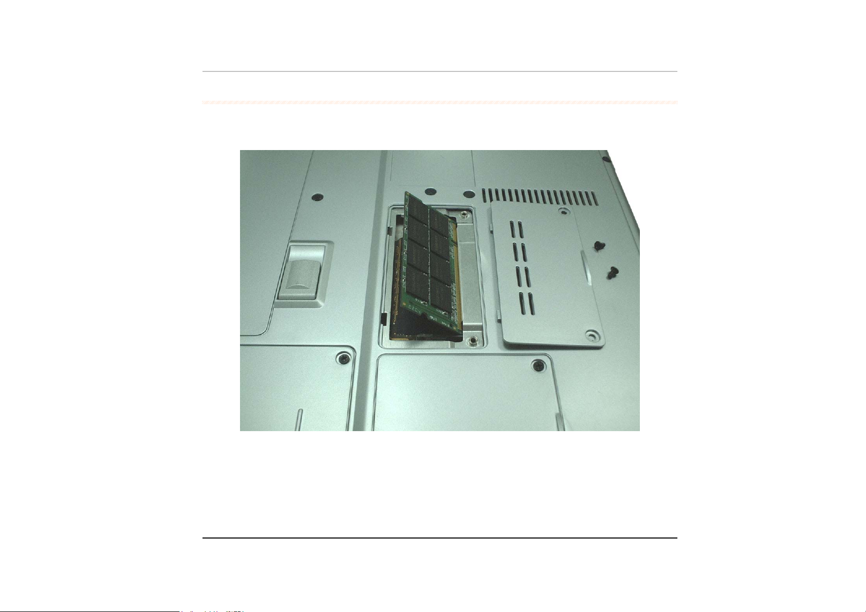
UUppggrraaddiinngg yyoouurr MMeemmoorryy
Refer to the following instructions and illustration for information on upgrading
your Mobile PC's memory.
Turn off the computer and disconnect the AC adapter and all peripherals.
11..
Turn the Mobile PC over so that the rear ports are facing you and locate the
22..
memory module compartment.
Remove the screws that secure the RAM module compartment cover and set
33..
- 79 -
Page 94

it aside in a safe place.
Remove the compartment cover and then angling it up and out.
44..
If you need to install a higher capacity module, gently push the edge clips on
55..
both sides to release the module. Angle the card slightly upward and gently
slide it from its edge connector slot. Store the card in the anti-static bag that
contains your new module(s).
To install the new memory card, hold the card with its gold edge connector
66..
toward the edge connector slot of the compartment. To help you orient the
cards, the edge connector has been made with two unequal-length sections.
You will only be able to insert the card in one direction.
Insert the edge connector into the slot. The gold edge connector of the card
77..
should not be visible when the card is fully inserted.
Press the card downward where you should hear an audible click as the
88..
latches of the connector secure the card in place.
Once the module is properly seated, you can replace the cover on this
99..
compartment.
80
Replace and tighten the screw.
1100..
Page 95

TThhee EEaassyy ttoo UUppggrraaddee HHDDDD MMoodduullee
The hard drive in your Mobile PC is made to be easily swapped out for upgrading.
You should back up your hard drive before attempting o change the hard drive.
Make sure that before you install a new drive, all the files in
your system should be backed up.
TToo uuppggrraaddee yyoouurr HHaarrdd DDrriivvee
Power down the system completely. Turn the system over with the front of the
11..
unit facing you.
Remove the three screws that secure the compartment cover and set them in
22..
a safe place.
Slide the HDD cover away from the compartment.
33..
- 81 -
Page 96
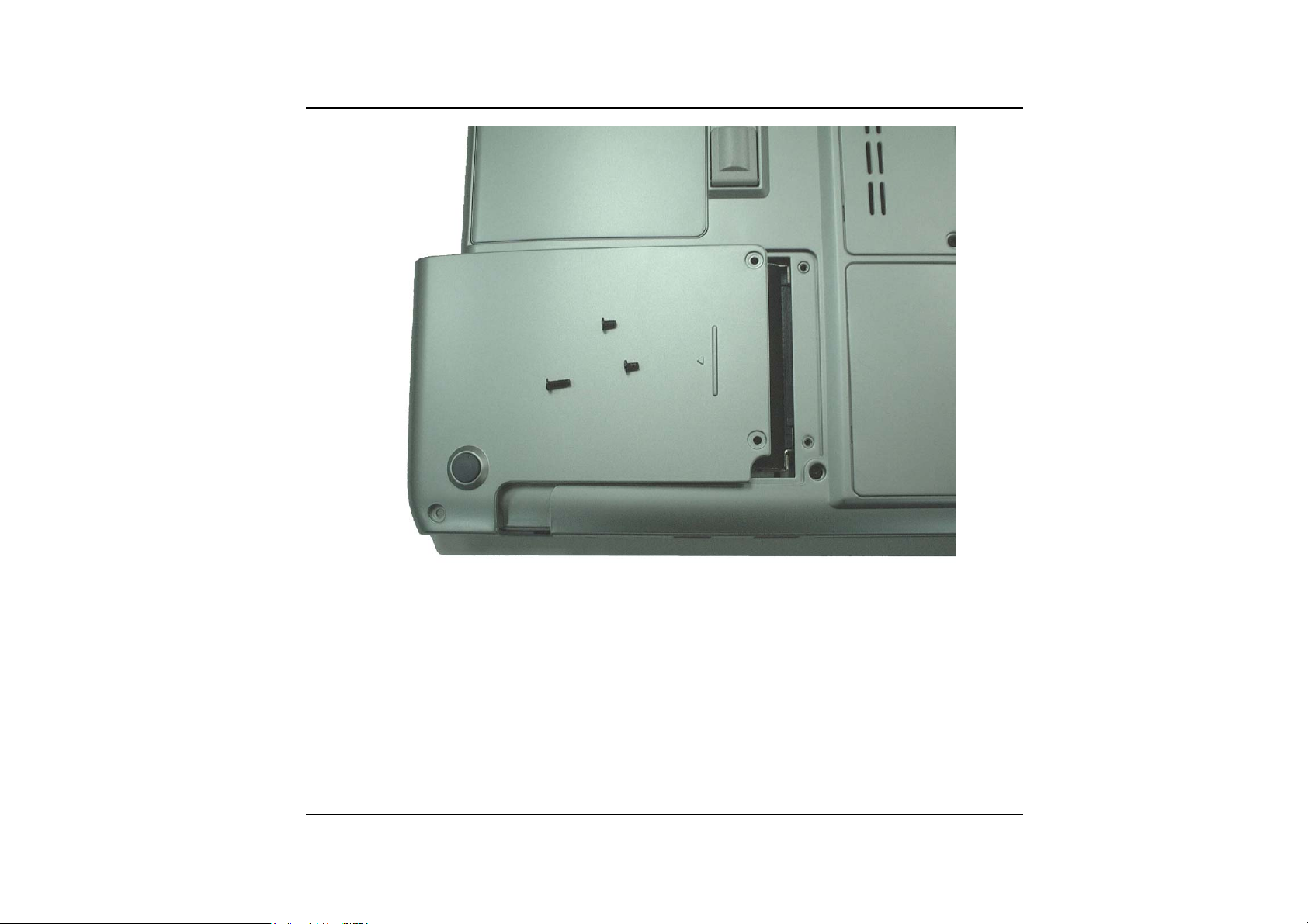
82
The drive is attached to a special bracket that secures it to the Mobile PC
44..
computer. There are 4 screws hold the bracket. Remove the screws and set
them in a safe place.
Push the HDD slightly in the direction of the arrow as shown in the illustration
55..
to release it from the pins of the drive.
Gently hold the grip of the HDD, lift it up to release from its compartment.
66..
Page 97
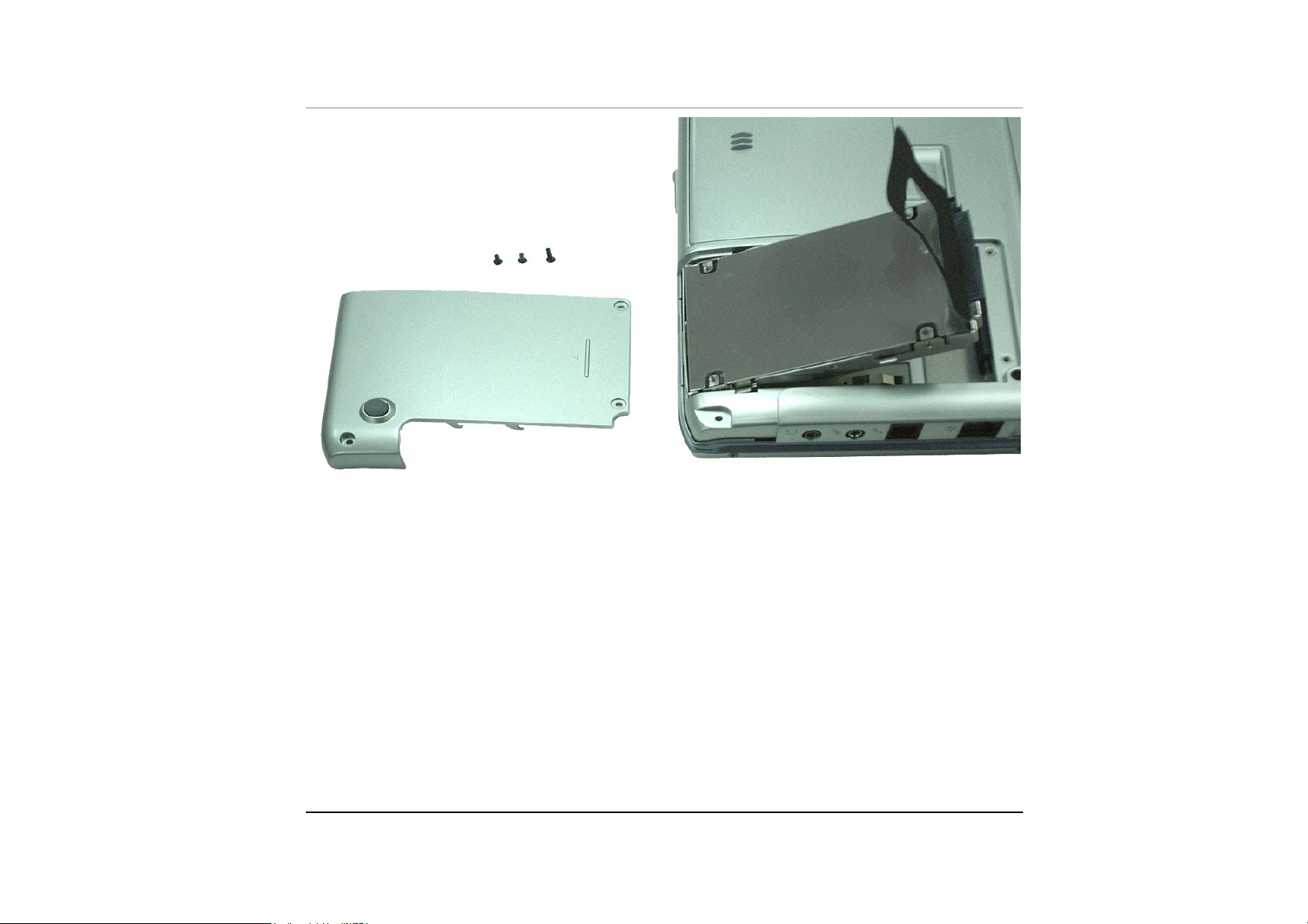
To install the new HDD, you will need to align the tabs on the drive bracket
77..
with the slots on the bay. Press down gently on the drive bracket until it
engages with the system. Do not force the drive into place this can bend the
pins on the hard drive.
Slide the compartment cover into place and be sure the screw holes on the
88..
cover align completely with the screw holes in the case.
Secure the cover with the three screws.
99..
- 83 -
Page 98

IInnssttaalllliinngg tthhee WWLLAANN
The Wireless Local Area Network (WLAN) Interface card enables high-speed
access without wires to network assets.
Open the LCD panel to at least 135 degree.
11..
1-1. Turn the system clockwise with 90 degree to let the system stand on your
desk to better disassemble the hinge cover.
1-2. Pull up the two hinge cover ears.
Turn the system back to sit on your desk and lift up the hinge cover on top of
22..
the keyboard.
2-1. Hinge cover is therefore disassembled from the system safely without any
scratch on the surface.
84
Page 99

Unscrew the screw attached on the keyboard.
33..
Lift up the keyboard.
44..
- 85 -
Page 100

Remove the two screws attached to the WLAN door.
55..
86
Open the WLAN door and connect the connector of the card and PCBA.
66..
 Loading...