

Page 1

1
ELITE GNS 430W
GNS 430W
INSTALLATION
AND
QUICK REFERENCE GUIDE
ELITE® Part No.
88293-001
Rev.10/08
Page 2

SUPPLEMENTS
2
INTRODUCTION
Congratulations on choosing the fi nest, most advanced
ELITE® software and hardware enhancement package
available. The Garmin GNS 430W designed in cooperation
with Reality-XP® represents ELITE’s commitment
to provide high quality training devices and software
incorporating easy to use avionics systems.
Before installing and getting started please take the
time to carefully review this manual to gain a thorough
understanding of the ELITE software and the GNS 430W
hardware. Proper installation and close attention to detail
are important to ensure proper functioning of the system.
ELITE® assumes the end-user is familiar with the basic
principles of fl ying, pilotage, GPS navigation, and overall
aeronautical knowledge. This guide is not designed to
be a step-by-step operational instructional guide on
the operation of ELITE® software or hardware, nor is it
intended to be a complete user guide of the Garmin® GNS
430W GPS system.
ELITE® highly recommends users of the ELITE software
and GNS 430W control module download the entire
Garmin 400W Series Pilot’s Guide and Reference free of
charge at:
http://www8.garmin.com/manuals/GNS430W_
PilotsGuideandReference_190-00356-00_.pdf.
Inclusion of Garmin copyrighted material in this
presentation does not imply any endorsement by
Garmin Ltd or its affi liates of the fl ight training material
provided by Reality-XP.
Page 3

3
ELITE GNS 430W
INSTALLATION
SYSTEM COMPONENTS
Your new ELITE® V8.5 should include the following
components:
ELITE® V8.5 Installation & User’s Guide•
ELITE® GNS 430W control module•
One USB cable•
One WiBu key•
ELITE® V8.5 software DVD•
ELITE® software box (not shown)•
ELITE® software Quick Start Installation •
Guide (not shown)
Control module mounting kit (Velcro or rubber •
feet, not shown)
If you are missing any of the above components,
contact ELITE® Customer Service at 407-277-7700 or
800-557-7590.
Page 4

SUPPLEMENTS
4
After following the software instructions provided in the
ELITE® Quick Start Installation you will install the GNS
430W control module. The “doghouse” shaped end of the
USB cable will plug in the back of the control module as
shown.
Before plugging the fl at end into your computer’s USB
port or USB hub, ensure the selector switch is in the
DOWN or POS 1. The selector switch is reserved for
future enhancements however it must remain in POS 1 for
complete functionality.
With your computer powered ON, once the fl at end of the
USB cable is inserted into the USB plug on your computer
or USB hub, follow the on-screen instructions carefully so
that the necessary AP 4000 drivers are installed.
Page 5

5
ELITE GNS 430W
OPERATION DESCRIPTION
COM Power/Volume1.
VLOC Volume2.
COM Flip-fl op3.
VLOC Flip-fl op4.
CLR (clear)5.
Direct-to6.
RNG (map range)7.
MENU8.
ENT (enter)9.
Small left knob (tunes kHz) & push to activate cursor10.
Large left knob (tunes mHz)11.
CDI Selector12.
OBS Selector13.
MSG (message)14.
FPL (fl ight plan)15.
PROC (procedures16.
Large right knob (selects page groups)17.
Small right knob (selects pages within groups) & push 18.
to activate cursor, and to select alpha numeric.
Page 6

SUPPLEMENTS
6
The ELITE® GNS 430W control module is laid out exactly
as the actual GNS 430W with the exception of the center
color LCD display. In order to keep costs low, ELITE®
displays the GNS 430W within the cockpit display of the
software. Full GNS 430W functionality remains intact.
In as much as the ELITE® V8.5 software suite is designed
primarily as an instrument trainer for both fl ight schools
and the home user, there are certain limitations within the
control module. The ELITE version of the GNS 430W does
NOT provide optional displays and programming such as
GDL49 Weather Datalink, GDL69/69A XM Satellite Datalink
or XM Satellite radio, TAWS or GPWS terrain alerts.
LEFT-HAND KEYS AND KNOBS
The COM Power/Volume
knob controls unit power and
communications radio volume.
Press momentarily to disable the
automatic squelch mode.
The VLOC Volume knob controls
audio volume for the selected
VOR/Localizer frequency. Press
momentarily to enable or disable
the ident tone.
The large left knob is used to tune the megahertz (mHz)
value of the standby frequency for the COM transceiver or
the VLOC receiver, whichever is currently selected by the
tuning cursor.
Page 7

7
ELITE GNS 430W
The small left knob is used to tune the kilohertz (kHz) value of
the standby frequency for the COM transceiver or the VLOC
receiver, whichever is currently selected by the tuning cursor.
Press this knob momentarily to toggle the tuning cursor
between the COM and VLOC frequency fi elds.
The COM Flip-fl op button is used to swap the active and
standby COM frequencies. Press and hold to select the
emergency frequency of 121.500.
The VLOC Flip-fl op button is used to swap the active and
standby VLOC frequencies.
BOTTOM ROW KEYS
The CDI button is used to toggle which navigation source
(GPS or VLOC) drives the external HSI or CDI.
The OBS button is used to select either manual or automatic
sequencing of waypoints. Pressing the OBS button selects
OBS mode which retains the current ‘active to” waypoint as
the navigation reference even after passing the waypoint.
In other words, it prevents sequencing to the next waypoint.
Pressing the OBS button again returns the unit to normal
operation with automatic waypoint sequencing. When OBS
mode is selected, the pilot may set the desired course to or
from a waypoint by using the “Select OBS Course” pop-up
window or an external OBS selector on the HSI or CDI.
The MSG button is used to view system messages and
pilot alerts such as warnings, and requirements.
The FPL button allows the pilot to create, edit, activate,
invert fl ight plans as well as access approaches, departures
and arrivals. The closest point to a fl ight plan feature is
also available by pushing the FPL button.
Page 8

SUPPLEMENTS
8
The PROC button allows the pilot to select and delete
approaches, departures and arrivals from the fl ight plan.
When using a fl ight plan, all available departure or arrival
procedures are suggested automatically. Otherwise, the
pilot may select the desired airport followed by the desired
departure or arrival procedure.
RIGHT-HAND KEYS AND KNOBS
The RNG button allows the pilot
to select the desired map range in
nautical miles. Press the UP arrow
side of the button to zoom out to
a larger area or press the DOWN
arrow to zoom in to a smaller area.
The Direct-To button allows access
to the direct-to function, which allows
the pilot to enter a destination waypoint and establishes
a direct course to the selected destination. This course
is indicated by a magenta line from the aircraft to the
destination waypoint.
The MENU button displays a specifi c list of operational
options. This options list allows the pilot to access additional
features or make settings changes as they relate to the
currently displayed page.
The CLR button is used to erase information, remove map
detailing or to cancel and entry. Pushing the CLR button
and holding for a few seconds will immediately display the
default NAV page.
The large right knob is used to select between the various
page groups such as NAV, WPT, AUX, or NRST. With the
on-screen cursor enabled, the knob allows the pilot to
move the cursor around the page. The knob is also used
to move the target pointer right (clockwise) or left (counter
clockwise) when the map panning function is active.
Page 9

9
ELITE GNS 430W
The small right knob is used to select between the various
pages within the page groups of NA V, WPT , AUX or NRST.
Push the knob momentarily to display the on-screen cursor.
The cursor allows the pilot to enter data and/or make a
selection from a list of options. The knob is also used to
move the target pointer up (clockwise) or down (counter
clockwise) when the map panning function is active.
Page 10

SUPPLEMENTS
10
GENERAL OPERATION
POWER ON
To power on the ELITE GNS 430W module you
must fi rst load and run the ELITE® program.
Click on the appropriate ELITE® icon to start
the ELITE® program.
Once the program loads and the desired aircraft is selected
the aircraft master switch and avionics master switch (if
equipped) must be turned on.
Turn the COM Power/Volume knob clockwise to turn on
the unit power and set the desired transceiver volume.
A welcome page will appear briefl y while the unit performs
a self-test, followed by the display of several brief pages
relating to obstacle, terrain, airport data, etc. are self-tested
to ensure proper operation.
Once the unit’s self-test is completed, the Database
Confi rmation Page is displayed, showing the effective
and expiration dates of the navigation database. Note:
The database dates shown will NOT refl ect the current
Jeppesen Navigational Database cycle. Your current NOS
or Jeppesen charts may not refl ect the ELITE® database
within the simulator. Press the ENT key to acknowledge
the Database Page and proceed to the Instrument Panel
Self-test page.
Page 11

11
ELITE GNS 430W
The Instrument Panel Self-test Page allows the pilot
to verify the ELITE® 430W is communicating properly
with the in-panel fl ight instruments—just as in the
actual aircraft. Compare on-screen indications with
the information depicted on the fl ight instruments such
as the CDI/HSI, RMI (if equipped) and/or external
annunciators. After verifying the proper operation of the
fl ight instruments, push the ENT key to display the Satellite
Status Page.
When the Satellite Status Page is displayed, keep in mind
the number and position of depicted satellites is simulated
and does not refl ect current satellite position. The Satellite
Status Page is for trainer use only and should not be
considered live, current data.
Page 12

SUPPLEMENTS
12
Note: The number and position of depicted satellites may
be displayed differently after each subsequent use of the
ELITE® trainer. This is in no way indicative of a defective
or faulty program.
SCREEN LAYOUT
The ELITE 430W’s display screen is divided into three
distinct “windows” or areas. The left 1/4 of the display
screen provides a COM window with active and standby
frequencies as well as the VLOC with both standby and
active frequencies. The active frequency is displayed in
white characters while the standby frequencies are shaded
blue.
The right 3/4 of the display consists of a GPS window
which shows the various navigation, waypoint information
and settings pages.
Page 13

13
ELITE GNS 430W
Each unique screen of
information is referred to as
a page. Pages are generally
selected using the small and
large right knobs, with the
cursor removed from the GPS
window. Review the next
several pages for details on
the arrangement of the GNS
430W’s main pages.
CURSORS AND FREQUENCY SELECTION
There are two separate cursors:
a tuning cursor and a GPS
window cursor. The turning
cursor is used to select either
the standby COM or VLOC
frequency. If desired, press the
small left knob to move the tuning
cursor to the VLOC window.
Then, use the small and large
left knobs to select the desired
frequency. The COM Flip-fl op
and the VLOC Flip-fl op keys
are used to activate the desired
frequency.
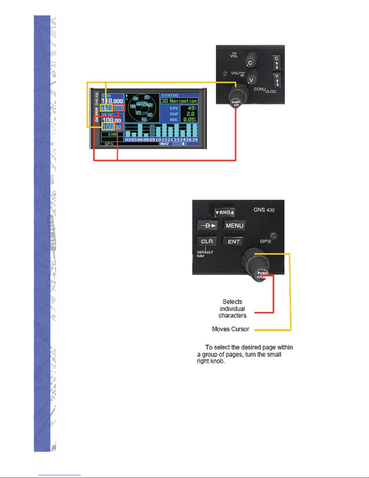
If the turning cursor is not currently in the desired window
such as COM or VLOC, press the small left knob marked
“PUSH C/V” momentarily. Turn the large left knob to dial
in the desired mHz value. For example, to select 118.700,
use the large left knob to select 1 18 portion. T urn the small
inner knob to select the desired kHz value, such as .700 in
our example of 118.700.
To activate the desired frequency, press the COMM Flipfl op key for COM frequencies, or the VLOC Flip-fl op key
for VLOC frequencies.
Page 14
SUPPLEMENTS
14
Remember, the white characters are
ACTIVE, and the blue characters are
STANDBY.
DATA ENTRY AND MAIN PAGE GROUPS
Data is entered into the 430W
by using the large and small
right knobs. The large right
knob is used to move the cursor
around a page. The small right
knob is used to select individual
characters for the highlighted
cursor location.
The GNS 430W’s main pages
are divided into four separate
page groups: NAV, WPT, AUX
and NRST. Each group is
composed of multiple pages.
The page groups are selected
using the large right knob. The
individual pages are selected
using the small right knob.
The bottom right corner of the screen indicated which
page group is currently being displayed, the number of
screens available within that group, and the placement of
the current screen within that group indicated by a white
square icon.
Page 15

15
ELITE GNS 430W
In the example below, the current Page Group is WPT
(selected by the large right knob) and have page one of 10
selected. (Selected by the small right knob)
To select the desired page group, press and hold the CLR
button to select the default NAV page. Turn the large right
knob to select the desired page group.
Page 16

SUPPLEMENTS
16
NAV PAGE GROUP
The NAV Page Group includes six pages.
Default NAV
Map
NAV/COM
Page 17

17
ELITE GNS 430W
Position
Satellite Status
VNAV
Page 18

SUPPLEMENTS
18
WPT PAGE
The WPT Page Group includes ten pages.
Airport Location
Airport Runway Environment
Airport Frequencies
Page 19

19
ELITE GNS 430W
Airport Approach
Airport Arrival Procedure
Airport Departure Procedure
Page 20

SUPPLEMENTS
20
Intersection
NDB
VOR
Page 21

21
ELITE GNS 430W
User-Defi ned Waypoints
Page 22

SUPPLEMENTS
22
AUX PAGE GROUP
The WPT Page Group includes ten pages.
Flight Planning
Utility
Setup 1
Page 23

23
ELITE GNS 430W
Setup 2
Note: The fl ight plan pages are selected by pressing the
FPL button and using the small right knob to select the
desired page.
Page 24

SUPPLEMENTS
24
AUX PAGE GROUP
The NRST Pages consists of eight pages. To access an
element push the small right knob to highlight the desired
element followed by the ENT button. When the word
“Done?” is fl ashing, push the ENT button again to activate.
You may also select an airport’s tower frequency by
turning the big right knob and highlighting the appropriate
frequency. Push ENT to load the frequency. Push ENT
again when the word “Done?” is highlighted. Use the COM
Flip-fl op to switch from the standby to active mode.
Page 25

25
ELITE GNS 430W
Page 26

SUPPLEMENTS
26
Nearest Intersections
(Can utilize the Direct-To feature)
Nearest NDBs
(Can utilize the Direct-To feature)
Nearest VORs
(Can utilize the auto-tune feature)
Page 27

27
ELITE GNS 430W
Nearest USER waypoints
(Can utilize the Direct-To feature)
Nearest ARTCC
(Can utilize the auto-tune feature)
Nearest FSS
(Can utilize the auto-tune feature)
Page 28

SUPPLEMENTS
28
Nearest Airspace
(Can utilize the Direct-To feature)
FLIGHT PLANS
CREATING A NEW FLIGHT PLAN
Press the FPL button.1.
Turn the small right knob to display the Flight 2.
Plan Catalog.
Turn the large right knob to highlight “Create 3.
New Flight Plan?” and select ENT.
A blank Flight Plan page appears. Using the 4.
big and small right knobs, enter the identifi er
of the departure waypoint and push the ENT
key.
Page 29

29
ELITE GNS 430W
Repeat all the steps in step 4 above to enter 5.
additional waypoint data.
After all waypoint data has been entered, 6.
press the small right knob to return to the
Flight Plan Catalog page.
Page 30

SUPPLEMENTS
30
SELECTING A DIRECT-TO DESTINATION
Press the Direct-To button. The Select Direct-To
Waypoint page appears with the waypoint identifi er fi eld
highlighted.
Use the small and large right knobs to enter the identifi er of
the desired destination waypoint. The destination waypoint
can be an airport, fi x, navaid (VORTAC, NDB) or a user-
defi ned waypoint.
Push the ENT button to confi rm your selection. The word
“Activate” will be highlighted in fl ashing white. Push the
ENT button again to activate the Direct-To function.
Page 31

31
ELITE GNS 430W
SELECTING A DIRECT-TO DESTINATION FROM THE
MAP PAGE
Select the MAP page from the NAV Page Group.
Press the small right knob to display the Group panning
cursor. (Arrow) Turn the right & left knobs to position the
cursor at the desired location.
Press the Direct-To button over the desired location.
Page 32

SUPPLEMENTS
32
Press the ENT button once to select. “Activate” will be
highlighted in fl ashing white.
Push the ENT button again to activate the waypoint route
and to navigate to the selected waypoint. The route of fl ight
will be drawn with a solid magenta line from the current
position to the selected waypoint.
Page 33

33
ELITE GNS 430W
VIEWING AIRPORT INFORMATION
Turn the large right knob to select the WPT Page Group.
WPT appears in the lower right corner of the screen.
Turn the small right knob to select the desired page, in this
example, runway information.
Page 34

SUPPLEMENTS
34
Push the small right knob to highlight the various
runways.
Page 35

35
ELITE GNS 430W
Turn the small right knob to the selected runway. Push
the ENT button. The primary tower frequency will be
fl ashing with green highlighting. Press ENT to autotune
the frequency in the COM standby mode. Use the COM
Flip-fl op to make the frequency active.
Page 36

SUPPLEMENTS
36
AUTO TUNE A FREQUENCY FROM A LIST
Select an airport using the right large and small knobs.
Turn the small right knob to the third page of the WPT
page.
Push the right small knob to activate the cursor.
Page 37

37
ELITE GNS 430W
Turning the right large knob, scroll through to the desired
frequency.
Press the ENT button which will move the selected
frequency into the COM standby box
Press the COM Flip-fl ip button to make the frequency
active. Note the “RX” in the COM box which indicates the
COM receiver is receiving audio.
Page 38

SUPPLEMENTS
38
DEFAULT NAV PAGE
The following symbols are used on the Default NAV page
below the CDI to depict the active leg of a fl ight plan or a
Direct-to:
Page 39

39
ELITE GNS 430W
MAP PAGE
The following symbols are used on the
MAP Page which depict airports, navaids,
intersections and heliports:
Page 40

SUPPLEMENTS
40
BOTTOM ROW ANNUNICA TORS AND MESSAGES
Page 41

41
ELITE GNS 430W
APPROACHES
The fi rst step in fl ying an approach is you must fi rst have
an active direct-to or an active fl ight plan which ends at an
airport with a published approach.
Push the PROC button to display the 1.
procedures page.
Turn the large right knob and highlight 2.
“Select Approach?” followed by pushing the
ENT button.
A window will be displayed on top of the 3.
primary display showing all the available
procedures. Turn the large right knob to move
the highlight bar to the desired procedure
and push the ENT button.
Page 42

SUPPLEMENTS
42
A second window will be displayed showing 4.
all the available transitions. Turn the large
right knob to move the white highlight bar to
the desired transition waypoint and push the
ENT button.
Turn the large right knob to highlight “Load?” 5.
or “Activate?” and push the ENT key.
Selecting “Load?” will add the procedure into
the active fl ight plan and allow uninterrupted
navigation and reserve the approach for
quick activation when needed. Selecting
“Activate?” overrides the enroute portion of
the active fl ight plan proceeding directly to
the approach portion.
Page 43

43
ELITE GNS 430W
For non-GPS approved approaches, a 6.
window will be displayed reminding the pilot
that GPS guidance on such an approach
is ONLY for monitoring only and the use of
the VLOC receiver portion of the GNS 430
and the external CDI or HSI for primary
navigation and course guidance. To confi rm
this reminder window you must highlight
“Yes” and push the ENT button.
Push the CDI button to select VLOC which 7.
will assign VLOC guidance to the CDI/HSI.
On the Flight Mode Annunciator and verify
“VLOC” is illuminated white. You do NOT
want to see the green GPS illuminated.
Page 44

SUPPLEMENTS
44
Once the approach is loaded, the entire 8.
approach procedure will be displayed
including waypoints, fi xes, holds, etc.
For additional details, push the small right 9.
knob to move the highlight bar on the
particular aspect of the approach. The word
“Done?” will be highlighted in white. Push the
“ENT” which will return to the Active Flight
Plan page.
Page 45

45
ELITE GNS 430W
Not all approaches are approved for GPS use. As of
now, most larger airports have published RNAV/GPS
approaches with many replacing the old NDB approach
procedures by “GPS overlays”. As an approach is selected,
there may be “ILS 09L” or “RNAV 09L” with “GPS” noted
to the right. If an approach with “GPS” is available and
selected, the approach procedure can be fl own using the
GPS receiver.
Page 46

SUPPLEMENTS
46
ACTIV ATING AN APPROACH WITH VECTORS-TOFINAL
When utilizing the “Activate Vector-To-Final” mode, this
mode allows to activate the fi nal course segment of the
approach. This mode assumes ATC will give you vectors
to the fi nal approach course and guides you to intercept
the fi nal approach fi x before reaching the Final Approach
Fix.
With the desired approach loaded in the 1.
active fl ight plan, push the PROC button to
display the procedures page.
Turn the large right knob to highlight “Activate 2.
Vector-To-Final?”
Push the ENT key.3.
The Default NAV page will be displayed 4.
providing course guidance, distance, bearing,
ground speed, and estimated time enroute.
Page 47

47
ELITE GNS 430W
FLYING THE APPROACH
Due to the wide range of available approach procedures, the
specifi c steps presented in this guide will vary according to
the approach selected. It is suggested to keep the following
guidelines in mind when fl ying an approach using ELITE®
and the GNS 430W control module.
The ELITE® 430W is designed to compliment •
your printed simulator approach plates and
improve your situational awareness during
simulated fl ight. Nevertheless, you must
always fl y the approach as it is depicted on
the approach plate.
You will generally select the destination airport •
as the last waypoint in the active fl ight plan or
by using the Direct-to button. By doing so, the
desired waypoint will automatically appear
when choosing the “Select Approach?” mode
from the procedures page. Otherwise, you
must fi rst choose an airport followed by the
approach procedure.
When a ground based ILS approach is loaded, •
the desired frequency is automatically placed
in the standby position in the VLOC window.
Push the VLOC Flip-fl op key to move the
frequency into the active position.
If the VLOC receiver is to be used for the •
approach, make sure you switch the external
CDI/HSI to “VLOC” by pushing the CDI
button.
An “Auto ILS CDI” setting provides •
automatic switching to “VLOC” as the fi nal
approach course is intercepted. When the
ILS approach is activated and the correct
frequency is in the VLOC window, the unit
Page 48

SUPPLEMENTS
48
will automatically switch when within 1.2
nautical miles left or right of the approach
course. However, this switching can take
place anywhere from 2.0 to 15.0 nautical
miles from the Final Approach Fix. To avoid
abrupt CDI changes the switching occurs
gradually. This automatic switchover does
not occur automatically when confi gured for
the KAP140 autopilot system as Auto ILS
CDI Selection is prohibited by limitations
within the KAP140.
As progress is made to the next waypoint, a •
waypoint alert message such as “NEXT DTK
120º “ will appear in the lower-right corner of
the display.
During the approach, alerts will advise •
course changes with standard-rate turns
such as “TURN TO 195º” will appear in the
lower right corner of the display.
For GPS approaches, RAIM will monitor •
satellite conditions and alert using the
word“INTEG” at the bottom left corner of
the display if protection limits can not be
maintained. Should the “INTEG” alert occur,
the GPS receiver should not be used as the
primary navigation source. You must revert
to an alternate navigation source such as an
ILS.
LPV, LNAV+V, and L/NAV approaches will •
automatically downgrade to LNAV if GPS
integrity can not be maintained. There is no
need to switch guidance by other navigation
equipment unless GPS LNAV is unacceptable
or integrity degrades further.
Page 49

49
ELITE GNS 430W
Within 31 nautical miles of the destination •
airport, the CDI scaling will transition from
2.0nm ENR mode 1.0nm terminal or TERM
mode. In addition, when leaving a departure
airport, CDI scaling will transition from 1.0nm
to 2.0nm when 30 miles out. GPS-based
approaches will see a second transition when
within 2.0nm of the FAF scaling from 1.0nm
to full scale defl ection. (approach mode, or
“LNAV, LNAV+V, L/LNAV, OR LPV”)
A “RT to xxxº x S” or “L T to xxxº x S will appear •
in the lower right corner to alert whenyou are
at a safe distance to initiate the procedure
turn. the procedure turn is displayed on the
map page, however guidance through the
turn is not provided except through the roll
mode of steering-equipped autopilots.
Alerts for proper holding pattern entry such •
as “HOLD DIRECT” are displayed in the
lower right corner of the display. Waypoint
sequencing is automatically suspended
(indicated by “SUSP” in the lower left center
of the display) at the holding waypoint. Push
the OBS button again to return to automatic
waypoint sequencing. For course reversals,
waypoint sequencing is suspended for one
circuit around the holding pattern only, after
which it will return to automat waypoint
sequencing.
The CDI will guide you through a DME arc. •
You will need to keep the needle centered as
you fl y along the arc.
As you cross the MAP, “SUSP” will appear in •
the lower left center of the display indicating
that automatic sequencing of waypoints
Page 50

SUPPLEMENTS
50
is suspended at the MAP and a FROM
indication will appear on the CDI/HSI.
FLYING THE MISSED APPROACH PROCEDURE
After crossing the MAP, push the OBS •
button. The next waypoint in the approach
is automatically displayed as the destination
waypoint.
Follow the published missed approach •
procedures as depicted on the approach plate
including climb and heading instructions.
An alert message in the lower right corner •
of the display will suggest entry procedures
for entering the holding pattern such as
teardrop, parallel or direct. As the holding
pattern is fl own, an automatic time appears
on the default NAV page. The timer will
automatically reset on the outbound side of
the hold when abeam the hold waypoint. The
timer will once again reset as the inbound
turn is begun within approximately 30º of the
inbound course.
The GPS will provide course guidance ONL Y •
on the inbound side of the holding pattern.
Guidance is provided along the entire holding
pattern if roll-steering autopilot systems are
used.
When leaving the holding pattern to fl y •
the approach again or another approach
push the PROC key to “Select Approach?”
or “Activate Approach?” as previously
discussed. You may use the direct-to button
to select another destination.
Page 51

51
ELITE GNS 430W
ANNUNCIATION FUNCTIONAL DESCRIPTION
LPV Lateral Precision with Vertical Guidance
Approach. Fly to LPV minimums. A yellow
background indicates the approach is
safe to continue but a downgrade to
LNAV may occur.
L/VNAV Lateral Navigation and Vertical
Navigation approach. Fly to
LNAV/VNAV minimums.
LNAV+V Non-precision GPS approach with
advisory vertical guidance. Some
LNAV/VNAV approaches are not
yet marked in the database and will
show up as LNAV+V. If the approach
plate shows the approach as
LNAV/VNAV, it can be fl own to LNAV/
VNAV minimums.
MAPR Indicates the system is providing missed
approach integrity and CDI full-scale
defl ection +/- 0.3nm.
ENR Indicates the system is in en-route
mode. CDI full-scale defl ection is 2.0nm
or current CDI scale selection whichever
is smaller.
TERM Indicates the system is in terminal mode,
CDI full-scale defl ection is 1.0nm or
current CDI scale whichever is smaller.
DPRT Indicates the system is using
non-precision approach integrity.
OCN Oceanic mode, full-scale defl ection is
2.0nm
LOW ALT For LNAV+V, LNAV/VNAV, or LPV
approaches, indicates aircraft’s
estimated altitude is lower than the fi nal
approach waypoint by more than 50
meters.
Page 52

SUPPLEMENTS
52
COPYRIGHT
Copyright 1989 - 2008 by
ELITE Simulation Solutions
Im Schorli 1
8600 Dubendorf, Switzerland
All rights reserved.
Under the copyright laws, this manual may not be copied, reproduced
or distributed in any form or by any means, in whole or in part, without
the written consent of the author: ELITE Simulation Solutions AG. Y our
rights to the software are governed by the accompanying software
license agreement.
Every effort has been made to ensure that the information in this
manual is accurate. ELITE Simulation Solutions AG is not responsible
for printing or clerical errors.
All terms mentioned in this manual that are actually known to be
trademarks or service marks are listed below. ELITE Simulation
Solutions AG cannot attest to the accuracy of this information. Use of
a term in this manual should not be regarded as affecting the validity
of any trademark or service mark.
Apple Logo and Macintosh are registered trademarks of Apple
Computer. IBM and PC are trademarks of International Business
Machines Corporation Windows 95, 98, 2000, Me, NT and XP are
trademarks of Microsoft Corporation. Jeppesen is a trademark of
Jeppesen Sanderson Inc.
LICENSE AGREEMENT
This is a license agreement and not an agreement for sale. A license
agreement is a legal agreement between you, the end user (You), and
ELITE Simulations solutions AG “Licensor.” Please read this software
license agreement “Agreement” carefully. If you do not agree with the
terms and conditions of this Agreement, you should contact ELITE
Simulation Solutions AG within 30 days from the invoice date.
Ownership of the Software
The enclosed ELITE software program “Software” and the
accompanying written materials are owned by ELITE Simulation
Solutions AG, Switzerland, and are protected by United States
copyright laws, by laws of other nations, and by international treaties.
Page 53

53
ELITE GNS 430W
Grant Of License
Licensor grants to you the non-exclusive right to use one copy of the
Software on the RC-1 in accordance with the terms of the Agreement.
You may not install the software on a network or on a computer other
than the one that came as a component of the RC-1 Advanced ATD
without express written permission from ELITE Simulation Solutions..
Restrictions on Use and Transfer
You may not use the software on another computer or loan, rent,
transfer , or assign them to another user except as part of the permanent
transfer of the RC-1 aviation training device.
You may not copy the Software, except that you may transfer the
Software to a single hard disk for backup or archival purposes. You
may not copy the written materials.
You may permanently transfer the RC-1 Software and accompanying
written materials (including the most recent update and all prior
versions) if you retain no copies and the transferee agrees to be
bound by the terms of this Agreement. Such a transfer terminates
your license. You may not rent or lease the Software or otherwise
transfer or assign the right to use the Software, except as stated in
this paragraph.
You may not reverse engineer, decompile, modify, disassemble or
create derivative works based upon the Software in whole or part.
Term and Termination
This license terminates if you fail to comply with any provision of this
Agreement. You agree upon termination to destroy the Program, with
all copies, modifi cations and merged portions in any form, including
any copy in your computer memory or on a hard disk.
Limited Warranty
Licensor warrants that the Software will perform substantially in
accordance with the accompanying written materials for a period of
90 days from the date of your receipt of the Software. Any implied
warranties on the Software are limited to 90 days. Some states do
not allow limitations on duration of an implied warranty, so the above
limitation may not apply to you.
LICENSOR DISCLAIMS ALL OTHER WARRANTIES, EITHER
EXPRESS OR IMPLIED, INCLUDING BUT NOT LIMITED TO
IMPLIED WARRANTIES OF MERCHANTABILITY, FITNESS FOR
A PARTICULAR PURPOSE, AND NON-INFRINGEMENT, WITH
Page 54

SUPPLEMENTS
54
RESPECT TO THE SOFTWARE AND THE ACCOMPANYING
MATERIALS. This limited warranty gives you specifi c legal rights. You
may have others, which vary from state to state.
LICENSOR’S ENTIRE LIABILITY AND YOUR EXCLUSIVE REMEDY
SHALL BE, AT LICENSOR’S CHOICE, EITHER (A) RETURN OF THE
PRICE PAID OR (B) REPLACEMENT OF THE SOFTWARE THAT
DOES NOT MEET LICENSOR’S LIMITED WARRANTY AND WHICH
IS RETURNED TO LICENSOR WITH A COPY OF YOUR RECEIPT.
Any replacement Software will be warranted for the remainder of
the original warranty period or 30 days, whichever is longer. These
remedies are not available outside the United States of America.
This Limited Warranty is void if failure of the Software has resulted
from modifi cation, accident, abuse, or misapplication.
IN NO EVENT WILL LICENSOR BE LIABLE TO YOU FOR DAMAGES,
INCLUDING ANY LOSS OF PROFITS, LOST SAVINGS, OR OTHER
INCIDENTAL OR CONSEQUENTIAL DAMAGES ARISING OUT OF
YOUR USE OR INABILITY TO USE THE SOFTWARE. Because
some states do not allow the exclusion or limitation of liability for
consequential or incidental damages, the above limitation may not
apply to you.
This Agreement constitutes the entire agreement between you and
Licensor regarding the Software and supersedes any other information,
advice or representation given to You by Licensor or its dealers,
distributors agents or employees. This Agreement is governed by
the laws of the State of Florida, U.S.A. and Switzerland, whichever
is applicable. If any provision of this Agreement is found to be invalid
by any court of competent jurisdiction, the balance of this Agreement
shall remain in full force and effect.
If You have any questions concerning this Agreement or wish to
contact Licensors for any reason, please write to:
ELITE Simulation Solutions
5700 Dot Com Court Suite 1010
Oviedo, FL 32765-3400
U.S. Government Restricted Rights. The Software and documentation
are provided with Restricted Rights. Use, duplication, or disclosure
by the Government is subject to restrictions set forth in subparagraph
(c)(1) of The Rights in Technical Data and Computer Software
clause at DFARS 252.227-7013 or subparagraphs (c)(1)(ii) and (2)
of Commercial Computer Software - Restricted Rights at 48 CFR
52.227-19, as applicable.
Page 55

ELITE® GNS 430W SOFTWARE AND
HARDWARE REGISTRATION
Please take a few moments to complete and return this
registration form. It will allow ELITE® to provide better
service, and allow you to be the fi rst to know about future
software upgrades, enhancements and other features.
We will NOT sell your information to third parties and all
information is confi dential.
What is the highest pilot license you currently hold?
What is the highest pilot license you currently hold?
Private
Instrument
Neither, I’m not a pilot.
Which ELITE® software do you currently own?
ELITE® Core
ELITE® Premium
None, this is my fi rst ELITE® purchase
What is your main reason for purchasing the ELITE®
software package with the GNS 430W control
module?
I’m a simulator enthusiast
I want to learn the 430W for my own knowledge
My airplane has an 430W and I want to learn
more about it.
Do you have any other fl ight simulation products? If
so, which one(s)?
Microsoft Flight Simulator 98, 2000, 2004, FSX
ASA On-Top, Jeppesen
X-Plane
Page 56

Are there any other ideas or products you would like to see
ELITE® incorporate into the next software or hardware
product?
Name:
________________________________________
Address:
________________________________________
________________________________________
________________________________________
Phone:
________________________________________
Complete and return to:
ELITE Simulation Solutions
5700 Dot Com Court, Suite 1010
Oviedo, Florida 32765
 Loading...