

Page 1
Sink
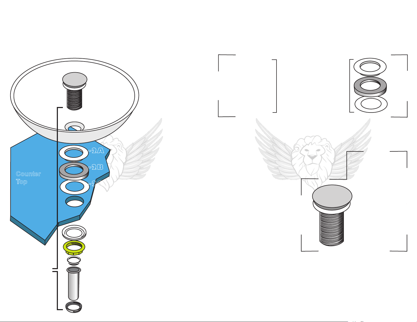
Counter
Top
1H connects
to bottom end
of 1C
Pop-up Drain and
Mounting Ring Set
Parts List:
-1A
-1B
-1C
-2A
-2B
-2C
-1D
-1E
-1F
-1G
-1H
1) Pop-up Drain:
1A) Umbrella Cap
1B) Flat White Rubber Gasket
1C) Threaded Body
1D) White Rubber Gasket
with Recessed Groove
1E) Large Brass Nut
1F) Black Rubber “T” Gasket
1G) Tail Pipe
1H) Tail Pipe Screw
2) Mounting Ring:**
2A) White Rubber “T” Gasket
2B) ABS Mounting Ring
2C) Flat White Rubber Gasket
**Mounting Rings are used for Round
Bottom Bowl Vessel Sinks with
No Overflow Drain.
of our flat bottom glass sinks, ceramic
sinks that sits on a leveled base or flush
to your counter top
overflow drain),
Model#:
P01008
and
P01*
*For Model# P01
drains, disregard
the use of the
mounting ring
shown as parts
2A-2B.
If you have one
(all with NO
please skip to step
#2 on the next page.
Pop-up Drain Set Assembly
Before we start, please make sure the following:
- Diameter of hole drilled in counter top is 1.75”
- Thickness of counter top does NOT exceed 2”
- Your drain model is P01008
If you have
drain
DISREGARD
model#:
-----MOUNTING-----
P01
Please skip to step #2 and disregard
the use of the mounting ring, also in
the diagram to the left.*
1. Set up mounting ring with gasket (parts 2A-2C)
as shown on diagram to your left and line these parts up
with the hole drilled in your counter top.
2. Set your vessel sink on top of mounting ring set, lining up
the sink drain hole with mounting ring
set and hole drilled in counter top.
3. Disassemble your pop-up drain
until you’re left with the top portion of
the drain (parts 1A-1C) like so
------------------------------------------------->
4. Insert top portion of pop-up drain as
is, all the way through the sink drain
hole, mounting ring set and drilled
hole in counter top. Bottom end of
part 1C will protrude from
underneath your counter top.
5. From underneath the counter top,
re-apply white rubber gasket
with recessed groove (part 1D) back onto the threaded body (part 1C) with the
groove face up against the counter top underside.
6. Re-apply large brass nut (part 1E) by hand. You may use an appropriately sized
wrench if needed. Make sure you DO NOT overexert this application. If too
much pressure is applied, you may crack the sink drain hole rim, and/or strip the threads
on the drain’s body or the brass nut itself.
7. Place black rubber “T” gasket on top of tail pipe (parts 1F-1G) as shown on
diagram to your left.
8) Apply tail pipe screw (par t 1H) as shown in diagram to
connect to bottom end of part 1C.
RING SET
*Mounting Rings are used
Bottom Bowl Vessel
**You may remove part
1A and set side if deemed
more convenient during
-1A**
-1B
-1C
-2A
-2B
-2C
ONLY for Round
Sinks with No
Overflow Drain.
installation.
Pg 3
 Loading...