

Page 1
USER MANUAL
GEBRAUCHSANLEITUNG
MANUEL D’UTILISATION
MANUALE D’USO
MANUAL DE FUNCIONAMIENTO
MANUAL DO USUÁRIO
GEBRUIKSAANWIJZING
РУКОВОДС ТВО П О ЭКСПЛУАТАЦИИ
ユーザーマニュアル
用户手册
El in ch ro m LTD – EL B 50 0 T TL U ni t – 01 .2 01 8
ELB 500 TTL UNIT
EN
DE
FR
IT
ES
PT
NL
RU
JP
CN
Page 2

TABLE OF CONTENTS
INTRODUCTION 2
ELB 500 TTL POWER PACK CHARACTERISTICS 3
BEFORE YOU START 5
GENERAL USER SAFETY INFORMATION 5
CONTROL PANEL 10
MENU FEATURES 17
RADIO FEATURES & SETUP 17
SKYPORT MODE 18
PHOTTIX MODE 18
FLASH MODE SETUP 19
ELB 500 BATTERY 21
ELB 500 HEAD 25
TROUBLESHOOTING 27
MAINTENANCE 30
DISPOSAL AND REYCLING 32
TECHNICAL DATA 33
LEGAL INFORMATION 36
DECLARATION OF CONFORMITYUSA & CANADA 37
EN
1
Page 3

INTRODUCTION
Dear photographer,
Thank you for buying the Elinchrom ELB 500 TTL unit.
All Elinchrom products are manufactured using the most advanced
technology. Carefully selected components are used to ensure the
highest quality and the equipment is submitted to many tests both
during and after manufacture. We trust that it will give you many
years of reliable service.
Please read the instructions carefully before use, for your safety and
to obtain maximum benefit from many features.
EN
This manual may show images of products with accessories, which
are not part of sets or single units. Elinchrom set and single unit
configurations may change without advice and may differ in other
countries. Please find actual configurations at www.elinchrom.com
For further details, upgrades, news and the latest information
about the Elinchrom System, please regularly visit the Elinchrom
website. The latest user guides and technical specifications can be
downloaded in the “Support” area.
Technical data, features and functions of Elinchrom flash units,
accessories and the Skyport system may change without advice.
The listed values can differ due to tolerances in components, or
measuring instruments. Technical data, subject to change. No
guarantee for misprints.
Keep this user manual for later information and reference.
2
Your Elinchrom-Team
Page 4

ELB 500 TTL CHARACTERISTICS
The ELB 500 TTL unit implements manual, action and TTL modes.
The TTL (Through the Lens Metering) mode allows you to access
fully automatic exposure setups according to your digital camera
capabilities.
If you wish to work in the manual mode or combine both modes,
the unit enables you to save the TTL exposure parameters as a
starting point when passing to the manual mode.
The unit supports Skyport radio remote control and HSS at full
power. It offers totally flexible asymmetry and the fastest flash
durations at lower power levels.
The ELB 500 TTL unit has the following characteristics:
• 500 Ws maximum output power in manual and TTL modes
• Full asymmetry with two outlets A & B
• 7 f-stops power range
• Action mode for optimised flash duration
• Dedicated ELB 500 Head
• LED modelling lamp power in 40 adjustment levels
• New ergonomic design with large OLED colour display
• Accepts two remote options: Elinchrom PRO and Odin2.
Earlier Skyport versions are supported (HSS and TTL
is supported on the Skyport Transmitter Plus HS with a
firmware update)
• Improved weather protection for outlets
• USB socket for firmware updates and Sync socket 3.5 mm
• Complete unit only 2.49 kg / pack alone 1.7 kg / Battery Box
0.73 kg
EN
3
Page 5

ELINCHROM TTL MODE CHARACTERISTICS
• 7 f-stop flash power range
• TTL +/- 3 f-stops adjustable in 1/3 steps.
• LED modelling lamp is adjustable in 40 power steps
• Compatible with Canon and Nikon. Other camera brands
will follow.
• Also compatible with Phottix Odin2 radio triggers for Canon,
Nikon and Sony
MANUAL MODE CHARACTERISTICS
• Full asymmetry
EN
• Compatible with all Skyport Transmitters
• Flash power in 1/10 f-stop steps
• 1/20000 s flash duration at 7.1 ws
• Saves the TTL power as a starting point for the manual mode
ELB 500 LI-ION BATTERY FEATURES
• Lightweight Li-Ion battery technology, only 0.73 kg
• Approx. 400 flashes at full power.
• Battery charging time 100 min. to 90%
• Easy battery locking system
• Compatible with ELB 400 charger (19279)
4
Page 6

ELB 500 HEAD FEATURES
• Ultra-compact design with flexible 2.5 m cable
• Universal use: single head for Hi-Sync and normal mode
• Dedicated flash tube for the ELB 500 head
• LED modelling lamp 14W (40 steps), 5200K, 90 CRI
• 7 mm umbrella shaft
• Q mount for Quadra accessories
• Optional Quadra Reflector Adapter MK-II (26342) to adapt to
EL - accessories
BEFORE YOU START
GENERAL USER SAFETY INFORMATION
• Flash units are powerful light sources. Please be aware of
the danger, or inconvenience, that they may present to some
persons and children.
• Keep flash units out of reach of unauthorised persons
whenever possible.
• Keep flash units away from children!
• According to safety regulations, we draw your attention
to the fact that electronic flash units are not designed
for extreme outdoor use, in damp or dusty conditions
and should not be used after being exposed to sudden
temperature changes causing condensation. The humidity
protection conforms to the norms of IP20.
• Do not use without permission in restricted areas (such as
hospitals, laboratories etc.).
• Do not use near flammable / explosive material. Keep
minimum 1m or more distance to any object.
EN
5
Page 7

• Never flash into the eyes of a subject without warning. Close
use, may affect eyesight.
• The ambient temperature whilst the unit is in use: min. -20°C
(-4°F) up to max. 35°C (95°F). Storage temperature: -10°C up
to 60°C, optimal charging temperature: 0°C up to 45°C.
• There is high voltage and there can be high currents, so
please apply all the usual safety precautions when handling
the unit.
• Do not connect the flash head to to the pack without a
mounted and working flashtube due to high voltage at the
exposed terminals!
• Flash systems store electrical energy in capacitors by
EN
applying high voltage.
• The units may retain an internal charge for a considerable
time even though disconnected from the battery. Internal
defective charge capacitors may explode whilst the unit is in
use, so never switch on a flash unit, once it has been found
to be faulty.
• For your safety, never open or disassemble your flashes.
Only an authorized service engineer should open or attempt
to repair this unit.
• Always switch off the flash unit before changing accessories.
• The unit, the flashtube and accessories may become very
hot during and after use! To avoid injuries, handle with an
insulating cloth or wait until parts have cooled down. Avoid
direct sunlight, which might heat up the flash unit and affect
the photocell efficiency. Protect the flash unit when used in
humid conditions, but ensure ventilation for cooling!
• On no account should any object be inserted into the
ventilation holes.
6
Page 8

• Use only original Elinchrom Accessories. Damaged cables,
glass domes and cases must be immediately replaced by
customer service.
WARNING: PHOTOSENSITIVITY / EPILEPSY / SEIZURES
A very small percentage of individuals may experience epileptic
seizures or blackouts when exposed to certain light patterns or
flashing lights. These conditions may trigger previously undetected
epileptic symptoms or seizures in persons who have no history of
prior seizures or epilepsy. If you, or anyone in your family, has an
epileptic condition or has had seizures of any kind, consult your
physician before using the EL unit.
IMMEDIATELY DISCONTINUE use and consult your physician
before resuming use of your EL unit if you or any person
experiences any of the following health problems or symptoms:
• Dizziness
• Eye or muscle twitches
• Disorientation
• Any involuntary movement
• Altered vision
• Loss of awareness
• Seizures or convulsion
BATTERY SAFETY NOTICE
IMPORTANT! FOR YOUR SAFETY do not use the Battery Pack
for a purpose other than those specified, USE WITH ELINCHROM
EQUIPMENT ONLY!
• To recharge the Battery Pack, use ONLY the Elinchrom
EN
7
Page 9

Li-Ion Battery Charger. If the recharging operation fails
to complete even when a specified recharging time has
elapsed, immediately stop further recharging and disconnect
the charger.
• If the Battery Pack gives off odours, generates heat,
becomes discoloured or deformed, or in any way appears
abnormal during use, recharging or storage, immediately
remove it from the equipment or Battery Charger and stop
using it.
DO NOT USE A FAULTY, APPARENTLY DAMAGED OR
DEFORMED BATTERY PACK!
ELECTRICAL, CHEMICAL AND MECHANICAL HAZARDS
EN
• Do not disassemble, open or modify the Battery Pack.
• Do not connect the positive (+) and negative (-) terminals with
a metal object such as wire. Do not transport or store the
Battery Pack together with metal objects such as necklaces,
hairpins, etc.
• Do not pierce the Battery Pack with a nail or other sharp
objects, strike it with a hammer, or stand on it.
• Do not strike or throw the Battery Pack.
• If the Battery Pack leaks and electrolyte gets into the eyes,
do not rub them. Instead, rinse the eyes with clean running
water and immediately seek medical attention. Otherwise,
eye injury may result.
8
Page 10

OTHER HAZARDS
Store the Battery Pack in a location where children cannot reach it.
Do not put the Battery Pack into a microwave oven or a pressurized
container.
OUTDOOR USE
CAUTION! PROTECT THE BATTERY PACK AGAINST HUMIDITY!
This product is designed for dry use and should not come into
contact with water or dust. In humid conditions cover or otherwise
protect the battery. Do not immerse the Battery Pack in water /
seawater and do not allow it to get wet. The humidity protection
conforms to the norms of IP20.
TEMPERATURE PRECAUTIONS
To prevent overheating the product should not be covered whilst
in charge mode or in general use! Do not use, charge or leave
the Battery Pack near a heat source (+60°C or higher) such as
anopen fire, a heater or direct sunlight. If the Battery Pack has been
exposed to very cold conditions, sudden exposure to warm or
humid air may cause condensation and malfunction.
FLASH TUBES AND LED-MODELLING LIGHT SAFETY NOTICE
• Flashtubes and the LED-Reflector dishes may become very
hot during and after use!
• Never touch a flash tube or exchange it before the unit has
cooled down and is disconnected from the pack.
• Do not fire flashes from short distances directed towards a
person.
• Do not use near flammable / explosive material.
EN
9
Page 11
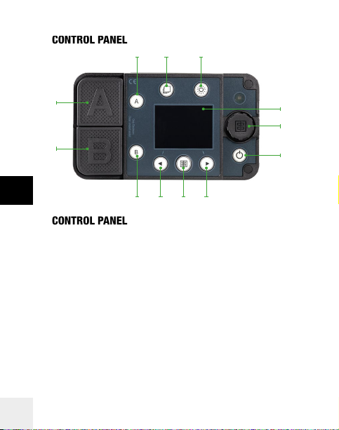
CONTROL PANEL
3
5
4
2
1
EN
CONTROL PANEL
1. Outlet B
2. Outlet A
3. Outlet A activation
4. Menu access
5. Modelling Lamp button: short push (on/off) / long push
(menu access)
6. 4.3’’ OLED Display
7. Scroll button
8. Unit switch On /Off
9. Menu navigation button (right / exit)
10. Flash test button
11. Menu navigation button (left / back)
12. Outlet B activation
10
6
7
8
9101112
Page 12

DISPLAY PANEL – DASHBOARD
The main dashboard displays essential information about one or
two head settings.
The colours of the upper bar correspond to the group number :
blue for group 1, yellow for group 2, red for group 3 and green
for group 4. It is possible to switch between black or white menu
background colour.
The dashboard changes automatically between the one and
two head view depending on the number of heads switched on.
Settings that are not enabled are not displayed in the dashboard.
For example, if the modelling lamp is switched off, the modelling
lamp symbol does not appear on the dashboard.
EN
11
Page 13

Dashboard views:
EN
One head view
654321
714
13
12
11 10
8
9
Two head view
12
Page 14

1. Skyport Synchronisation
2. Skyport frequency channel and group number
3. Photocell status
4. Action mode
5. Eco mode
6. Battery charge status
7. Power outlet B modelling lamp status
8. Power setting of the B outlet in f-stop equivalent
9. Flash Duration value of the B outlet*
10. Increase selected outlet by 1 f-stop
11. Decrease selected outlet by 1 f-stop
12. Flash Duration value of the A outlet*
13. Power setting of the B outlet in f-stop equivalent
14. Power outlet A modelling lamp status
* The flash duration is only visible at normal x-sync shutter speeds
(1/125 or 1/250s depending on the DSLR camera.
TTL MODE
The TTL (Through the Lens Metering) mode allows you to access
fully automatic exposure setups according to your digital camera.
The TTL values are automatically saved when passing to the
manual mode.
To operate the unit in the TTL mode, please use the radio remote
Skyport Pro.
The TTL mode is indicated in the upper bar of the dashboard (see
the image next page).
EN
13
Page 15

One head view Two head view
LED MODELLING LAMP
Modelling lamp settings are accessible through a dedicated
EN
Modelling Lamp button (5).
CONTROLLING THE LED / MOD LAMP MENU ACCESS
• A short press on the modelling lamp button turns on the LED
lamp of the ELB 500 Head.
• A long press on the modelling lamp button opens the
modelling lamp setup menu and switches on the modelling
lamp.
USE OF THE A AND B BUTTONS
• To enter into the modelling lamp menu, press and hold the
modelling lamp button.
• To enable / disable the LED of the A or B outlet, use a long
press on the A / B buttons.
• To select the A or B outlet LED, use a short press on the A /
B buttons, and turn the scroll button for individual LED power
14
settings.
Page 16
MODELLING LAMP MENU FEATURES
Enter the Modelling lamp setup menu with a long press on the
modelling lamp button. This operation will also switch on the
modelling lamps. You can directly adjust the total power of the
two modelling lamps by turning the scroll button. To select the
modelling lamp of the A or B outlet separately, press the A or B
button.
To exit the the menu press the button.
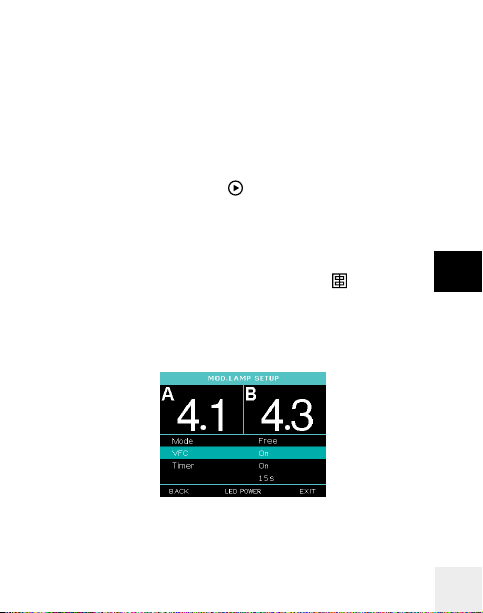
MODELLING LAMP SETTINGS
To access modelling lamp mode prop/free, VFC (visual flash
control) and the mod. lamp timer press the button (10).
With the scroll button go to the feature (turning) you want to modify.
Now press the scroll button to activate the option and select
(turning) the option and press to confirm.
EN
15
Page 17

MENU OPTIONS DESCRIPTION HOW TO
Mode Please choose
Free Power value of the
EN
Proportional Power value of the
VFC On / Off Visual Flash
Timer On / Off The mod. lamp
Timer value Modelling lamp
between the free
or the proportional
mod. lamp value
setting.
modelling lamp is
independent of the
flash power value.
modelling lamp
changes with the
flash power values.
Confirmation.
switches off after
the timeframe set
by the timer value.
timer, in sec
16
Shortcut mod. lamp
mode: short press
on the scroll button.
Use the scroll button
to set the value,
the setting will be
automatically stored.
Page 18

MENU FEATURES
DISPLAY PANEL – SETUP MENU
The colors of the setup menu correspond to the group number
setting, as in the main dashboard: blue for group 1, yellow for
group 2, red for group 3 and green for group 4.
To modify the menu settings, use the scroll button to navigate
and then press to confirm. In “Extras” the background of the user
interface can be switched from black to white.
RADIO FEATURES & SETUP
The radio setup mode allows you to choose which transmitter you
would like to use. The manual / TTL functionalities are supported
according to the transmitter type.
The ELB 500 TTL unit supports the Skyport HS (TTL functionallity is
only available after firmware update), Elinchrom Pro as well as the
Odin2 (Phottix) transmitters with TTL.
System Skyport Odin 2
Mode Off Normal Speed
Radio
Group 1-4
Frequency 1-20
Action On Off
Flash
Photocell On Off
mode
Recycling time Fast Eco
Auto stand-by Off 1-59 min.
Auto-off Off 1-60 min.
Extra
Ready tone On Off
Keyboard click On Off
Background Black White
Friendly name Set through computer software.
Firmware rev. *******
Serial number *******
Info
Life time In hours (hhhh:mm)
Flash count Total flash number
EN
17
Page 19

SKYPORT MODE
The Skyport options allow you to select
the pulse speed (Normal or Speed
Sync mode) of the synchronisation
signal and to define group and channel
settings.
The “normal” synchronization mode is good for long distances.
The “speed” sync mode might be needed for future cameras which
may require a faster communication. The distance range reduces
by approximately 50% in speed sync mode. Any change in these
EN
settings must be applied also to the EL-Skyport Transmitter to
enable communication between the devices!
Note: We suggest to use the Normal sync mode, which is
compatible with most DSLR camera.
Finally you can choose in which group and frequency you would
like to work. Change group settings to have better control for
example between main light and second lights. Change frequency
channel to avoid interference.
PHOTTIX MODE
In the TTL mode, the Odin2 (Phottix)
remote is also supported. The setup
menu is styled accordingly to the
current Odin2 interface (see the figure
next page).
18
Page 20

FLASH MODE SETUP
ACTION MODE
When the Action mode is activated,
the unit offers a fast optimised flash
duration, to freeze motion.
RECYCLING TIME
The flash mode menu enables you to set the recycling time to fast
or to eco, to save the battery.
EXTRAS
Extra settings include the power
setting, the audio setting options and
the background can be switched from
black to white.
Power settings help you define
standby and auto-off to save energy.
The audio options allow you to adjust the volume of the ready and
the key click tones, enabling you to work silently if necessary.
EN
19
Page 21

INFO
The Info section allows you to see the
friendly name of the unit and a number
of current usage statistics, such as
lifetime of the unit and the use of the
flashtube.
If you want to personalise the name
of your unit, use the Elinchrom App
for IOS or the WIN / MAC computer
software.The name will appear in the Info section (friendly name).
Shortcut: to see the friendly name of the unit when working with the
dashboards (outside of the setup menu), use a long press on the
Scroll button (7).
EN
Note: This feature is availble in the next Skyport software release
planned for 2018/2019.
20
Page 22

ELB 500 BATTERY
ELB 500 LI-ION BATTERY FEATURES
The Li-Ion Battery Pack is intended to be used with the ELB 500
TTL flash unit ONLY. Please use ONLY the original Elinchrom
Lithium Battery Charger!
Store the ELB 500 battery always disconnected from the flash unit.
The number of flashes may vary from battery to battery (due to
ageing, storage conditions etc.). Used Batteries may need to be
recycled. Check your local regulations!
AUTOMATIC FAULT DETECTION
The Battery is equipped with a Smart Protection System enabling
automatic disconnection of the Battery in case of temperature,
voltage or current range, excessions.
NO MEMORY EFFECT
• Charging can be applied and stopped at any charge level.
• There is no negative impact on Li-Ion cells caused by partial
charge and discharge cycles.
EN
21
Page 23

ELB 500 BATTERY PACK FUNCTIONS
1 4
EN
56
1. Signal interface between the ELB 500 battery and the ELB
500 TTL unit
2. ELB 500 battery charger socket
3. Battery terminals (fully symmetrical)
4. Locking mechanism
5. State of charge LED Indicator
6. Battery recovery button
BATTERY PACK CONNECTION INSTRUCTIONS
The Li-Ion Battery Pack is intended to be used with the ELB 500
TTL flash unit ONLY.
22
2
3
Page 24

TO CONNECT YOUR BATTERY TO THE ELB 500 TTL UNIT:
1. Place the ELB 500 unit on a flat, dry and clean surface.
2. Place the charged Li-Ion ELB 500 Battery Pack on a clean
surface
3. Place the ELB 500 housing over the ELB 500 Battery Pack.
4. Press smoothly down onto the ELB 500 housing until you
hear two clicks (left / right)
5. Visually check, that the Battery Pack is well connected on
both sides of the unit.
TO DISCONNECT THE BATTERY PACK FROM THE ELB 500 TTL UNIT:
1. Place the ELB 500 TTL pack on a flat, dry and clean surface.
2. Press the locking buttons on both sides and lift the unit as
shown in the picture below.
CHARGING INSTRUCTIONS
ELB 500 LI-ION CHARGER (19277)
• Connect the ELB 500 Charger (19277) first to the Li-Ion
battery and then to the mains.
• Charge progress is displayed by a flashing green LED.
• The constant green LED indicates that the battery is
completely charged.
• The ELB 500 Battery charges in approximately 100 minutes.
EN
23
Page 25

CHARGE DURATION
The ELB 500 Battery charges to 90% in approximately 100
minutes. However, the charge duration may vary depending on the
battery’s initial state of charge.
CAUTION! The charge duration will be significantly longer if the
battery has been left completely discharged for weeks.
STATE OF CHARGE INDICATION
The battery includes a monitoring circuit which shows the available
capacity of the battery when the state of charge button is pressed.
EN
80 – 100 %
60 – 80 %
40 – 60 %
20 – 40 %
< 20 % flashes
CHARGING / DISCHARGING RECOMMENDATIONS
• The Battery Pack can be used / discharged at ambient
temperatures from -10 °C to +60 °C.
• The Battery Pack can be charged at ambient temperatures
from 0 °C to +45 °C. Charging is not recommended at
temperatures below 0 °C.
24
Page 26

LI-ION CAR CHARGER (11038)
• Connect the Li-Ion Car Charger (11038) first to the 12V (or
24V) power socket and then to the Li-Ion battery.
• Charge progress is displayed by a red LED.
• After approx. 180 minutes of charging, a green LED indicates
that the battery is charged up to 95%
ELB 500 HEAD
ELB 500 HEAD CHARACTERISTICS
The new ELB 500 Head features an ultra-compact design with
flexible 2.5 m cable, and 7 mm umbrella shaft.
Enjoy the universal use: a single head for seamless transition from
lower shutter speeds up to Hi-Sync and back, both in TTL and
manual modes!
Experiment with the full range of Quadra accessories thanks to the
Q mount. Use Quadra Reflector Adapter MK-II (26342) to use the
full sized Elinchrom accessory system.
Implements a daylight 14W LED Modelling lamp with 5200 K and
90 CRI, adjustable in 40 steps.
ACCESSORY REMOVING / FITTING ADVICE
1. Always switch the power pack off, before attaching accessories.
2. Mount the ELB 500 head onto a tripod and lock the security
screw.
3. Press the ELB 500 head locking knob firmly down and turn the
reflector to the left.
4. Now pull the reflector from the head and replace with another
reflector.
EN
25
Page 27

FLASHTUBE REPLACEMENT
1. Switch the power pack off.
2. Disconnect the flash cable from the power pack.
3. Place the Head horizontally on a rigid, clean and dry surface.
4. Allow the flashtube to cool down.
ALWAYS USE A PROTECTIVE GLOVE TO REMOVE THE
FLASHTUBE!
5. Hold the Head firmly whilst removing and replacing the
flashtube.
6. Remove the security spring from the flashtube and pull the
flashtube firmly out of the terminals.
7. If the tube is broken, use security gloves to avoid cutting
EN
yourself and use an insulated tool to pull out the electrodes.
Never touch the metal electrodes.
8. Now replace with a new correct original Elinchrom flashtube.
An insulated tissue or security gloves MUST BE USED.
Any contact with your fingers on the tube, can cause dark
markings on the tube when used.
9. Check that the tube is correctly aligned (central) and that the
trigger contact is gripping the tube with the security wire.
10. Re-connect and test the head as usual.
26
Page 28

TROUBLESHOOTING
SOFT RESET
To reset all settings to default values, push the MENU (4.) and the
LEFT buttons (11.) at the same time and hold for at least 1 second.
The unit will reboot and will clear all working parameters. This will
not reset the counter in the “Info” menu.
WARNING MESSAGES
Wait until the unit has cooled down.
The unit will switch back to the normal
operation as soon as the temperature
decreases to a normal working level.
EMPTY BATTERY
When the battery is empty, the EL bouton
is blinking red. Plug the charger and wait
about 4 min. until the unit shutdown.
Press to switch-on the unit.
HEAD ERROR
The “head error” message appears if a
Quadra head is connected which is not
the ELB 500 head.
Please ensure that only the ELB 500 head
is used with the ELB 500 TTL unit.
Never plug any head of other brands into this unit, apart from
dangerous voltages, this would destroy the unit and the head!
EN
27
Page 29

ERROR TABLE
ERROR NUMBER DESRIPTION SOLUTION
1 Capacitors over
4 Charge Timeout Restart after 2
6 Unstable voltage
13 Battery current
EN
31 Ignition voltage
BATTERY TROUBLESHOOTING
The Battery is equipped with a Smart Fault Detection System
allowing it to disconnect automatically to prevent damage to the
Li-Ion cells. If the fault cause is removed, the battery will return
to the normal mode automatically. PLEASE CONTACT YOUR
DISTRIBUTOR if it’s impossible to recover from the fault or the
battery is often dispaying a fault mode.
LI-ION CHARGER TROUBLESHOOTING
NO LED’s ARE LIGHTING UP: The charging process is not
possible or the charger is out of order. Please contact your local EL
distributor.
voltage
(Charge hold error)
fault (battery
current overtime)
error
Restart after 2
min.-> Service
min.-> Service
Restart after 2
min.-> Service
Restart after 2
min.-> Service
Restart after 2
min.-> Service
28
Page 30

MAINTENANCE
The ELB 500 TTL power pack and heads require only very little
maintenance. To ensure secure operation please check the
following points regularly before connecting the head to the power
pack:
• Ensure that the contacts of the flash head connector are not
burned or corroded.
• The flash cable should not have any marks or cuts. The high
voltages carried can be dangerous!
• Ensure that the plug-in flash tube is correctly fitted.
• Do not use water to clean dust and dirt from the head.
• Ventilation grids must be clean and free of any tape etc.
CAUTION!
Under no circumstances open any part of the equipment. The ELB
500 TTL unit is not user serviceable and contains dangerous high
voltage. In the event of difficulty contact your Elinchrom Service
partner.
REGULAR CHECK
National safety regulations require frequent safety checks of the
electrical equipment. The ELB 500 unit should be checked once
a year. This check not only guarantees safety; it also protects the
value of the unit.
EN
29
Page 31

RETURN TO CUSTOMER SERVICE
To achieve maximum protection of the unit when sending it in for
service, the original packaging should be kept.
For service and sales, please contact your local ELINCHROM
Distributor. http://elinchrom.com/distrib.php
STORAGE AND TRANSPORTATION RECOMMENDATIONS
To improve the lifetime and security of your battery, please
disconnect the ELB 500 battery for storage. To avoid progressive
battery discharge (so called SELF-DISCHARGE*) which can cause
a DEEP DICHARGE MODE**, please do not store fully charged
battery packs for more than 3 to 6 months without use. If you have
several batteries please use them all or alternate among them.
EN
Note: Store only recharged batteries and disconnected from the
power pack.
*SELF-DISCHARGE MODE
Small losses of charge are observed during storage of a charged battery (selfdischarge), which is a natural process.
**DEEP DISCHARGE MODE
If the battery is not recharged over a long period of time (several months or
more), the self-discharge process may progressively cause the battery to enter
a state of DEEP DISCHARGE.
RECOVERY FROM THE DEEP DISCHARGE MODE
Plug the charger into the battery. After approximately 6 min the
battery will wake up and the charging process will restart normally.
30
Page 32

TRANSPORTATION
Use only the original cartons or cases when you travel or ship flash
units to avoid transportation damages. Try to avoid condensation
related problems, acclimatise flash units before using them.
Ideally discharge flash units before transporting them and wait 30
minutes after the mains cable has been removed so the unit has
cooled down. Never drop a flash unit; the flashtube and internal
components could break.
Please refer to our separate TRAVELLING BY AIR AS A
PASSENGER Instructions (73042) for current transportation
regulations.
DISPOSAL AND RECYCLING
This device has been manufactured to the highest standards from
materials which can be recycled or disposed of in a manner that is
not environmentally damaging. The device may be taken back after
use to be recycled, provided that it is returned in a condition that is
the result of normal use.
Any components not reclaimable will be disposed of in an
environmentally acceptable manner. Used Batteries may need to
be recycled. Check your local regulations!
If you have any question on disposal, please contact your local
office or your local ELINCHROM distributor (please visit our website
for a list of all ELINCHROM distributors worldwide).
EN
31
Page 33

TECHNICAL DATA OF ELB 500 TTL POWER PACK
Product Name and article NUM ELB 500 TTL (10232.1)
Accessories ELB 500 Li-Ion Battery (19297)
ELB 500 Head (20190)
ELB 500 Charger (19277)
Li-Ion Battery Car Charger
(11038)
Snappy for ELB 500 TTL
(19254)
EN
Flash capacity 500 Ws/J
Power distribution Full asymmetry
F-Stop (1m, 100 ISO, reflector
48°) ELB 500 Head
Power range ws/J 7.1 - 500
Power range f-stop, manual
mode
Power range f-stop, TTL mode 7 f-stop in 1/3 increments
Flash modes TTL / Manual
Action mode, on/off Optimised fast flash duration
32
Main features
100%: 64.8
7 f-stop in 1/10 increments
Page 34

Radio receiver (built-in) Skyport protocol (20
Recycling FAST at full power 2 sec.
Recycling ECO at full power 3.5 sec.
Flash specifications
Best flashduration in Action
mode at min. power (T0.1)
Flashes out of one charged
battery at max. / min. power
Color temperature in K° at
max. power
Color stability +/- 200 over 7 f-stops
Power stability 0.05%
LED Modelling lamp
Modelling lamp power 14W in 40 adjustment levels,
Color temperature in K at max.
power
Modeling lamp modes On / off, free, prop,
frequency channels, 4 groups)
/ Phottix Odin II (27 frequency
channels, 4 groups)
1/20 000 (7.1 ws)
400 / 28000
5500
6.3 - 2.3
5200
timer 1-60 s, VFC
Triggering
EN
33
Page 35

Optional remotes Manual only: Skyport
transmitter Plus
TTL and manual: Elinchrom
Pro / Phottix Odin II
Optical triggering distance Indoor: 15m
Outdoor: 10m line of sight
Sync socket 3.5 mm jack
Sync voltage 5V
Battery Pack
ELB 500 Li-Ion Battery / 19297 14.4V / 5 Ah / 72 Wh
EN
Charger input voltage range, AC
100 / 240V, 50-60 Hz
Charging time to 90% 100 min. (ELB 500 Battery)
Mechanics
Dimensions in cm / inches
(WxDxH)
Weight in kg / lbs, unit alone
Weight in kg / lbs, battery
Unit: 16.3 x 9 x 13.8
/ 6.4 x 3.6 x 5.4
Battery: 16.3 x 9 x 4.9
/ 6.4 x 3.6 x 1.9
Unit + Battery: 16.3 x 9 x 18.1
/ 6.4 x 3.6 x 7.12
1.7 / 3.83
0.73 / 1.60
34
Page 36

LEGAL INFORMATION
FCC CLASS B COMPLIANCE STATEMENT
Product name ELB 500 TTL (10232.1)
Accessories ELB 500 Li-Ion Battery (19297)
ELB 500 Head (20190)
ELB 500 Li-Ion Charger (19277)
Li-Ion Car Charger (11083)
Trade name ELINCHROM
Name of responsible
party
Phone +41 21 637 26 77
Fax +41 21 637 26 81
Email elinchrom@elinchrom.ch
This device complies with Part 15 of the FCC rules. Operation is
subject to the following two conditions:
1. This device may not cause harmful interference.
2. This device must accept any interference received, including
interference that may cause undesired operation.
This equipment has been tested and found to comply with the limits
for a Class B digital device, pursuant to Part 15 of the FCC Rules.
These limits are designed to provide reasonable protection against
ELINCHROM LTD
Avenue de Longemalle 11
1020 Renens
VD / Switzerland
EN
35
Page 37

harmful interference in a residential installation. This equipment
generates, uses and can radiate radio frequency energy and, if
not installed and used in accordance with the instructions, may
cause harmful interference to radio communications. However,
there is no guarantee that interference will not occur in a particular
installation. If this equipment does cause harmful interference to
radio or television reception, which can be determined by turning
the equipment off and on, the user is encouraged to try to correct
the interference by one or more of the following measures:
• Reorientate or relocate the receiving antenna.
• Increase the separation between the equipment and receiver.
• Connect the equipment into a power outlet on a circuit
EN
different from that to which the receiver is connected.
• Consult the dealer or an experienced radio/television
technician for help.
Modifications: Changes or modifications not approved by
ELINCHROM LTD can void the user’s authority to operate the
equipment.
36
Page 38

DECLARATION OF CONFORMITY USA AND CANADA
Industry Canada (IC) Compliance Notice
This device complies with Industry Canada license-exempt RSS
standard(s). Operation is subject to the following two conditions:
1. This device may not cause interference, and
2. This device must accept any interference, including
interference that may cause undesired operation of the
device
Avis de conformité aux normes d’Industrie Canada (IC).
Le présent appareil est conforme aux CNR d’Industrie Canada
applicables aux appareils radio exempts de licence. Son
exploitation est autorisée aux deux conditions suivantes:
1. Il ne doit pas produire de brouillage; et
2. Il doit accepter tout brouillage radioélectrique subi,
même si celui-ci est susceptible d’en compromettre le
fonctionnement.
CE MARKING
The shipped version of this device complies with the requirements
of European Directives related with it, therefore it is marked with
the CE conformity logo. For more information and to download the
European Declaration of Conformity of this product, please, visit our
website http://www.elinchrom.com/support_downloads.php
EN
37
Page 39

DOWNLOAD THE ELB 500 TTL USER MANUAL
Please get the complete user guide at this link:
http://www.elinchrom.com/support_downloads.php
DOWNLOAD CONFORMITY
Please find the declaration for EC conformity and USA & Canada
conformity on the Elinchrom website. Please check all security
documents before use!
http://www.elinchrom.com/support_downloads.php
LI-ION BATTERY SECURITY
EN
Please download the battery security:
http://www.elinchrom.com/support_downloads.php
38
Page 40

 Loading...