

Elinchrom ELB 1200 User Manual

Elinchrom LTD – ELB 1200 – 08.2017 – 73048
ELB 1200
USER MANUAL
GEBRAUCHSANLEITUNG
MANUEL D’UTILISATION
MANUALE D’USO
MANUAL DE FUNCIONAMIENTO
MANUAL DO USUÁRIO
GEBRUIKSAANWIJZING
РУКОВОДСТВО ПОЛЬЗОВАТЕЛЯ
安全ガイド
用户手册
EN
DE
FR
IT
ES
PT
NL
RU
JP
CN

User Manual
EN
1
Tolerances and specifications conforming to IEC and CE standards.
Te c hn i c a l d a t a i s s ub j e c t t o ch a ng e w it h o u t n o t i ce .
INTRODUCTION 2
ELB 1200 CARACTERISTICS 2
TECHNICAL DATA 3
USER SAFETY INFORMATION 4
CONTROL PANEL 6
DISPLAY PANEL – DASHBOARD 7
DEDICATED BUTTONS 8
• MODELLING LAMP
• USER SETTINGS
MENU FEATURES 11
• RADIO TRANSCEIVER FEATURES & SETUP
• FLASH MODE SETUP
• PHOTOCELL SETUP
• EXTRAS
• INFO
TROUBLESHOOTING 17
MAINTENANCE 18
STORAGE AND TRANSPORTATION 19
DISPOSAL AND RECYCLING 19
LEGAL INFORMATION 20

User Manual
EN
2
INTRODUCTION
INTRODUCTION
Dear photographer,
Thank you for buying the ELINCHROM ELB 1200 Unit. All Elinchrom products are
manufactured using the most advanced technology. Carefully selected components
are used to ensure the highest quality and the equipment is submitted to many tests
both during and after manufacture. We trust that it will give you many years of reliable
service.
Please read the instructions carefully before use, for your safety and to obtain maximum
benefit from many features.
Your Elinchrom-Team
Please read carefully the notes in this manual. This manual may show images of
products with accessories, which are not part of sets or single units. Elinchrom set and
single unit configurations may change without advice and may differ in other countries.
Please find actual configurations at www.elinchrom.com
For further details, upgrades, news and the latest information about the Elinchrom
System, please regularly visit the Elinchrom website. The latest user guides and
technical specifications can be downloaded in the “Support” area.
Technical data, features and functions of Elinchrom flash units, accessories and the
EL-Skyport system may change without advice. The listed values can differ due to
tolerances in components, or measuring instruments. Technical data, is subject to
change. No guarantee for misprints.
Please keep this user manual for later information and reference.
ELB1200 CARACTERISTICS
2x Outlets A + B with 2:1 (66%:33%) asymmetry and 1:1 (50%:50%) options. LED
illuminated outlets, show which head is active. Each connected head can be activated
or deactivated separately using the A and B buttons. Head recognition, shows if a Pro,
Hi-Sync, Action head is connected. Automatically displays the flash duration of each
(Pro / Action) head at all power levels. Elinchrom Creative Suite with strobo, delayed and
sequence features. USB for firmware updates.
Two versions of the ELB1200 Battery Pack are available:
• ELB1200 Li-Ion Battery HD 144 Wh (19296)
• ELB1200 Li-Ion Battery Air 90 Wh (19273)
The number of flashes may vary from battery to battery (due to ageing, storage
conditions etc.). Used Batteries may need to be recycled. Check your local regulations!

User Manual
EN
3
TECHNICAL DATA
Product Name and article number
ELB 1200 (10289.1)
Flash capacity (Ws/J)
1200
Power distribution
Asymmetrical 2:1 or symmetrical
F-Stop (1m, 100 ISO, reflector 48°) ELB 1200 Pro
100%: 128
F-Stop (1m, 100 ISO, reflector 48°) ELB 1200 Action
100%: 90.6
F-Stop (1m, 100 ISO, reflector 48°) ELB 1200 Hi-Sync
100%: 128
Power range F-stop
8.5
Powe r ra nge Ws / J
100%: 14 – 1200 / 50%: 7 - 600
66%: 14 – 791 / 33%: 7 - 396
Power increments in F-Stop
Dial: 1/10 – left/right buttons 1 F-Stop
Best flash duration t0.5 max. power ELB 1200 Action
1/8850 s at 33%, power setting 4.7
Recycling FAST to full power, in s
1.7
Recycling DEFAULT, to full power in s
3
Recycling ECO to full power, in s
6
Color temperature in K° at max. power
5500
Auto Power Dumping
Adjusts power settings automatically
Power stability
+/- 0.03 %
Modelling lamp modes
On, free, prop, timer 1-60 s, VFC, dimmer 5-100%
Flashes out of one charged battery at min / max. power
20000 / 215 (Li-Ion Battery Air, included)
36000 / 400 (Li-Ion Battery HD, optional)
LED run time 1 / 2 heads (set flash power to minimum
value)
Up to 80 / 40 min. (Li-Ion Battery Air, included)
Up to 120 / 60 min. (Li-Ion Battery HD, optional)
Li-Ion Battery Air (included, 19273)
36V / 2.5 Ah / 90 Wh
Li-Ion Battery HD (optional, 19296)
36V / 4.0 Ah / 144 Wh
Battery Box options
USB charge socket for mobile devices: 5V max. 1 Amp., shipping mode
setting, battery charge status with 4 LED’s
Quick Charger: approx. recharge time in h
1.5 (Li-Ion Battery Air, included)
2.5 (Li-Ion Battery HD, optional)
EL-Skyport
Built-in, 20 frequency channels, 4 groups
Sync voltage
5V compatible with all cameras
Sync socket
3.5 mm jack
Dimensions in cm, complete unit including handle &
battery box / without battery box (WxDxH)
18x13x28 / 18x13x22
Dimensions in cm Battery Box (WxDxH)
18x13x7.5
Weight in kg (lbs), without Battery Box
Weight in kg (lbs), complete unit
3.2 (6.8 lbs) (Li-Ion Battery Air, included)
4.3 (9.48 lbs) (Li-Ion Battery HD, optional)
Weight in kg, Battery Box
1.1 (2.4 lbs) (Li-Ion Battery Air, included)
1.5 (3.3 lbs) (Li-Ion Battery HD, optional)
Supplied with
ELB1200, battery box, quick charger, sync cable

User Manual
EN
4
USER SAFETY INFORMATION
• Flash units are powerful light sources. Please be aware of the danger, or
inconvenience, that they may present to some persons and children.
• Keep flash units out of reach of unauthorised persons whenever possible.
• Keep flash units away from children!
• According to safety regulations, we draw your attention to the fact that these
electronic flash units are not designed for outdoor use in excessively damp
or dusty conditions and should not be used after being exposed to sudden
temperature changes causing condensation. The humidity protection conforms to
the norms of IP20.
• Do not use without permission in restricted areas (such as hospitals, laboratories
etc.).
• Do not use near flammable / explosive material. Keep minimum 1m or more
distance to any object. Keep a general distance from other operating units.
• Never flash into the eyes of a subject without warning. Close use, may affect
eyesight.
• The ambient temperature whilst the unit is in use: min. -20°C (-4°F) up to max. 35°C
(95°F)
• There is high voltage and there can be high currents, so please apply all the usual
safety precautions when handling the unit.
• Flash systems store electrical energy in capacitors by applying high voltage,
please take care of open contacts and terminals.
• These units may retain an internal charge for a considerable time even though
disconnected. If it has been found to be faulty, please stop using it and return it for
repair.
• For your safety, never open or disassemble your flashes. Only an authorised
service engineer should open or attempt to repair this unit.
• Always switch off the flash unit before changing accessories.
• The unit, the flashtube and accessories may become very hot during and after
use! To avoid injury, handle with an insulating cloth or wait until parts have cooled
down. Avoid direct sunlight, which might heat up the flash unit and affect the
photocell efficiency. Protect the flash unit when used in humid conditions, but
ensure ventilation for cooling! On no account should any object be inserted into the
ventilation holes.
• Use only original Elinchrom Accessories. Damaged cables, glass domes and cases
must be immediately replaced by customer service.
FLASH TUBES AND LED-MODELLING LIGHT
• Flashtubes and the LED-Reflector dishes may become very hot during and after
use!
• Never touch a flash tube or exchange it before the unit has cooled down and is
disconnected from the power.
• Do not fire flashes from short distances directed towards a person.
• Do not use near flammable / explosive material.

User Manual
EN
5
WARNING: PHOTOSENSITIVITY/EPILEPSY/SEIZURES
A very small percentage of individuals may experience epileptic seizures or blackouts
when exposed to certain light patterns or flashing lights. Exposure to certain patterns
or stroboscopic effects may trigger epileptic seizures or blackouts in these individuals.
These conditions may trigger previously undetected epileptic symptoms or seizures
in persons who have no history of prior seizures or epilepsy. If you, or anyone in your
family, has an epileptic condition or has had seizures of any kind, consult your physician
before using the EL unit. IMMEDIATELY DISCONTINUE use and consult your physician
before resuming use of your EL unit if you or your child experience any of the following
health problems or symptoms:
• Dizziness
• Eye or muscle twitches
• Disorientation
• Any involuntary movement
• Altered vision
• Loss of awareness
• Seizures or convulsion

User Manual
EN
6
CONTROL PANEL
CONTROL PANEL FEATURES THE FOLLOWING
1. Outlet A
2. Outlet B
3. Outlet A on/off (located under the handle)
4. Power ratio between the outlets A and B
(66% : 33% or 50% : 50%), located under
the handle
5. Outlet B on/off (located under the handle)
6. Unit On /Off
7. Menu Access Button / Menu navigation
function
8. Left function button / Menu navigation
function / Power down by 1 F-stop
9. Scroll button (Menu navigation function ) /
Flash test (push) / power variation in 1/10th
10. Right function button / Menu navigation
function / Power up by 1 F-stop
11. LED Modelling Lamp Button : short push
(on/off) / long push (settings)
12. User setting button, toggle between
advanced and reduced display information
13. OLED Display
9 10
2
3
6
7
4
1
8
5
12
13
11

User Manual
EN
7
1. EL-Skyport synchronisation (normal or speed
sync mode)
2. EL-Skyport frequency channel and group
number
3. Photocell status
4. Modelling Lamp status
5. Battery charge status
6. Power outlet B / power ratio / head type
7. Power setting of the B outlet in f-stop
equivalents
8. Flash Duration value of the B outlet
9. Increase flash power by 1 f-stop (Effect of
function buttons)
10. Decrease flash power by 1 f-stop (Effect of
function buttons)
11. Flash Duration value of the A outlet
12. Power setting of the A outlet in f-stop
equivalents
13. Power outlet A / power ratio / head type
DISPLAY PANEL – DASHBOARD
The main dashboard displays a simplified view of one or two head settings.
The colours of the upper bar correspond to the group number : blue for the group 1, yellow for the group
2, red for the group 3 and green for the group 4. It is possible to switch between black or white menu
background colour.
The dashboard changes automatically between one and two heads view depending on the number of heads
switched on. Settings that are enabled are displayed on the dashboard. For example, if the modelling lamp is
switched on, the modelling lamp symbol will appear on the dashboard.
THE TWO HEAD VIEW DASHBOARD INCLUDE THE FOLLOWING FEATURES
1 2 3 4 5
6
7
811
12
13
910
One head view Two head view

User Manual
EN
8
DEDICATED BUTTONS
LED MODELLING LAMP BUTTON
• A short press on the modelling lamp button turns on the LED lamp of the ELB 1200 Head
for 15 seconds. Values can be changed from 1 to 60 seconds.
• A long press on the pilot lamp button opens the modelling lamp setup menu.
MODELLING LAMP SETUP MENU
Modelling lamp power value, timer settings and
the VFC function are accessible through the
Modelling Lamp Menu.
• Use A & B buttons to set modelling lamp
power values in the asymmetrical way.
• Ratio setting is accessible through the
button (A:B)
MODELLING LAMP SETTINGS MENU
MENU OPTIONS EXPLANATION HOW TO
Mode Free or
proportional
Switch between the free
and the proportional
modelling lamp power
setting
1. Press the Left Function button to enter
the menu.
2. Use the scroll button to set
proportional or free.
3. Confirm by pressing the scroll button.
Free The power value of
the modelling lamp is
independent of the flash
power value
1. Use Left Function button to leave the
menu
2. Use the scroll button to set the LED
power value, press to confirm.
Proportional The power value of
the modelling lamp is
proportional to the flash
power value
Fixed value.
Mode passes to FREE automatically if
the power settings are changed via the
scroll button.
VCF On/Off LED switches off, when
unit recharges. Optical
flash confirmation.
1. Press Left Function button to enter
the menu
2. Use the scroll button to toggle to
VFC.
3. Confirm by pressing the scroll
button.
Timer On/Off
• 1. Press Left Function button to
enter the menu
• 2. Use the scroll button to toggle
to Timer On/Off.
• 3. Confirm by pressing the scroll
button.
• 4. Use the scroll button to set the
value 5 – 60 s, press to confirm.
Timer value Modelling lamp timer,
5 – 60 s
exit To exit this menu, press the Right
Function button

User Manual
EN
9
USER SETTINGS BUTTON
The User Settings button displays the advanced menu. If two heads are attached, the display
adapts automatically. In this case, the central part of the dashboard displays the total power of
the two heads, in f-stop equivalents and in Joules.
The one head view displays the following features:
1 2 3 4 5 6
7
8
91011
12
13
ONE HEAD VIEW
1. EL-Skyport synchronisation (normal or
speed sync mode)
2. EL-Skyport frequency channel and group
number
3. Photocell status
4. Modelling Lamp status
5. Charge speed (fast / eco / in default mode
no info displayed)
6. Battery charge status
7. Flash power in f-stop equivalents
8. Flash mode settings (normal, sequence,
delayed, strobo)
9. Increase flash power by 1 f-stop
10. Modelling lamp status, when modelling
lamp is switched on
11. Decrease flash power by 1 f-stop
12. Flash power in Joules / Ws & flash duration
value (only displayed with Action and Pro
Heads)
13. Power outlet / power ratio / head type

User Manual
EN
10
1. EL-Skyport synchronisation (normal or
speed sync mode)
2. EL-Skyport frequency channel and group
number
3. Photocell status
4. Modelling Lamp status
5. Charge speed (fast / eco)**
6. Battery charge status
7. Power outlet B / power ratio / head type
8. Power setting of the B outlet in f-stop
equivalents and in Joules (Ws)
9. Flash Duration value of the B outlet*
10. Increase flash power by 1 f-stop
11. Total flash power of the two heads, in f-stop
equivalents and in Joules (Ws)
12. Flash mode settings (normal, sequence,
delayed, strobo)
13. Decrease flash power by 1 f-stop
14. Flash duration value of the A outlet*
15. Power setting of the A outlet in f-stop
equivalents and in Joules / Ws
16. Power outlet A / power ratio / head type
531 642
16
15
14
1213 1011
7
8
9
TWO HEAD VIEW
*Displayed with Action and Pro heads
** In default mode no info displayed

User Manual
EN
11
1
3
21
2
6
5
4
1. Menu selected
2. Selected menu options
3. Menu option settings
4. Exit menu navigation
5. Scroll button functions:
• Scroll to modify settings
• Press to confirm menu settings or enter
the menu option (select function)
6. Backward menu navigation
MENU FEATURES
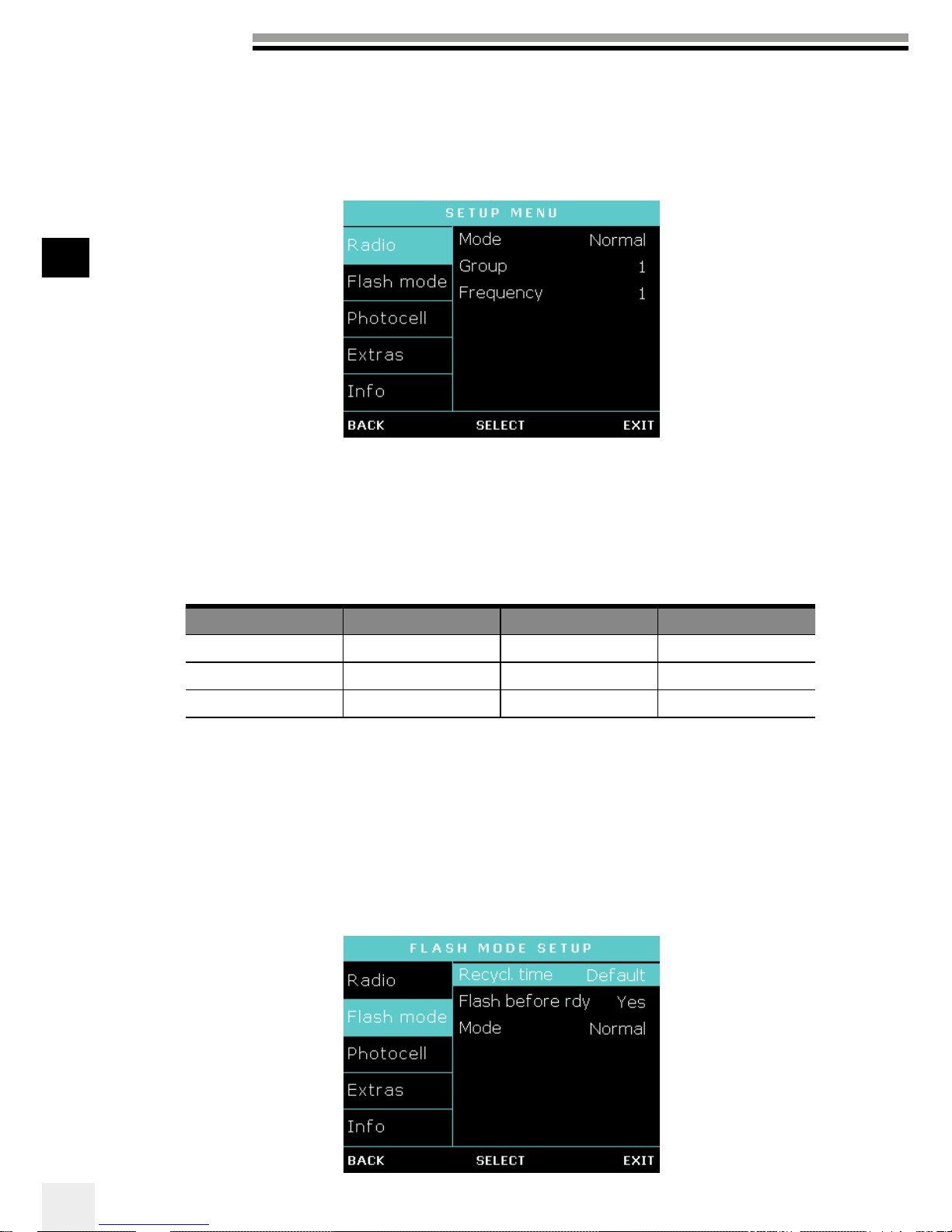
DISPLAY PANEL – SETUP MENU
The colors of the setup menu correspond to the group number setting, as in the main dashboard: blue is
group 1, yellow is group 2, red is group 3 and green is group 4.
It is possible to switch between black or white menu background colour, press long on the user button, but
leave the menu before.
To navigate in the menu, scroll with the scroll button and press to select.
User Manual
EN
12
When you work with the EL-Skyport Radio system you can choose the synchronization
speed. The “normal” synchronization mode is good when long distances are needed whereas
the “speed” synchronisation can be used when higher shutter sync speeds are needed, with
enabled medium format cameras. Any change in these settings must be applied also to the
EL-Skyport Radio Transmitter to enable communication between the devices! Normal sync
mode is the standard sync mode.
Finally you can choose in which group and frequency you would like to work. Change group
settings to have independent control multiple groups of lights. Change frequency channel to
avoid interference.
DISPLAY OPTION OPTION SETTINGS DEFAULT SETTING
Radio Mode Normal / Speed Normal
Group 1 to 4 1
Frequency (channel) 1 to 20 1
FLASH MODE SETUP
The flash mode menu enables you to configure your ELB unit to suit your style of shooting.
RADIO TRANSCEIVER FEATURES & SETUP
The Radio options allow you to select the synchronisation speed and to define group and
frequency settings.

User Manual
EN
13
To set the delay step to x 1, x 10 or x 100 steps press the button
The flash before ready feature gives you the choice between flashing the unit before full recycle
or to be able to flash only when the unit has fully recycled. You can also define recycling time
depending on the battery level left.
DISPLAY OPTION SUB- OPTION SUB-OPTION SETTINGS DEFAULT
SETTING
Flash
mode
Recycling time Eco / default
/ fast
Ye s/ no Default
Flash before
ready
Ye s/ no
Mode Normal /
Sequence
/ Delayed /
Strobo
Normal
Sequence Unit address 1 - 20 1
Sequence Tot a l un i t s 1 to 20 1
Sequence Sequence timeout 0.1’’-5.0’’ 2.0’’
Delayed Delay Steps: x1,
x10, x100
100 ms
Strobo Hz 1 - 20 1
Strobo Duration 0.5 – 5.0 s 2.0 s
Stay on default if you wish to do normal flash photography.
SEQUENCE SETUP
Use sequence mode to catch a moving sequence in a series of single frames with a number
of indexed flash units, for example, of a jumping person in up to 20 different images. The
following setup must be programmed in order to use the features.
Unit address : Every unit requires its own address; every time a trigger is released the
corresponding flash unit will respond. Up to 20 units can be addressed.
To t al u n it s : In d i c at e s th e t ot a l n u m be r o f a d d re s s e d fl as h u ni t s.
Sequence timeout : Time after which the sequence restarts back to first addressed unit.
The timeout can be programmed from 0.1s to 5s. This setting is the wait time after a sequence
is stopped, before it will restart from the beginning of the sequence.
DELAY SETUP
Set a delay for your ELB unit to flash with the set delay after triggering (e.g. second curtain).
The delay refers to the time (in ms) in which the unit should fire a flash after the camera
shutter has been opened. The delay time can be programmed from 1ms (0.001 s.) to 10000ms
(10 s.), enabling flash to be combined with ambient light sources.

User Manual
EN
14
To fin e - t un e t h e m i l li s e c on d s , t h e s c a le c a n b e m od i fi e d i n 1, 10 , a nd 1 0 0 s t e p s. P re s s t h e
press the right function button to choose your step. This option is only active in the flash delay
setup menu.
SUGGESTED VALUE TO SET ON THE ELB IN DELAYED MODE*
SYNC SPEED ON CAMERA EQUIVALENT IN MS SUGGESTED VALUE
1/60 16.6 9
1/50 20 12
1/40 25 17
1/30 33.3 23
1/25 40 30
1/20 50 40
1/15 66.6 52
1/13 77 68
1/10 100 90
1/8 125 115
1/6 166.6 145
1/5 200 185
1/4 250 235
0.3" 300 290
0.4" 400 370
0.5" 500 470
0.6" 600 580
0.8" 800 750
1" 1000 950
1.3" 1300 1200
1.6" 1600 1500
2" 2000 1900
2.5" 2500 2400
3.2" 3200 2900
4" 4000 3800
5" 5000 4800
6" 6000 5800
8" 8000 7700
10" 10000 9700
* tested with canon EOS 5D. Suggested for fullframe camera.

User Manual
EN
15
STROBO SETUP
Take an image with stroboscopic effects and open camera shutter. The overlapping moving
sequence is visible in one frame.
• Frequency Hz: Number of flashes per second. Programmable from 1 to 20Hz.
• Duration window: Time during of the moving sequence you wish to capture. Programmable
from 0.5 s. to 5 s.
Note: The unit must be set in fast recycling time in the “power settings” menu. If the error sound
is heard, this means the recycling time cannot keep up. Please reduce the Hz setting or the flash
power to a lower value.
The photocell options allow you to set up the optical flash trigger to off, on and if required, the
pre-flash options for the perfect synchronisation with speedlight preflash sequences.
PHOTOCELL SETUP
DISPLAY OPTION OPTION SETTINGS NOTE
Photocell Mode Off / On / Preflash
Setup Auto Only accessible in « preflash mode »
Use the scroll button, go to Auto
mode and select this (suggested to
automatically count the number of
flashes when the speedlight is fired
at the photocell, and set the correct
number.)
Preflash cnt
(only experienced
users)
Manual / 1-20 Only accessible in « manual setup »
Use this option only if you know the
number of pre-flashes the speedlight
fires, plus the main flash.
Time frame
(only experienced
users)
0.5 ‘’-5.0’’ Only accessible in « manual setup »
Block time
(only experienced
users)
0.5 ms – 5.0 ms Only accessible in « manual setup »

User Manual
EN
16
DISPLAY OPTION SETTINGS
Extras Auto std-by off / 1 min – 60 min
Auto - off off / 1 min – 60 min
Ready tone To n e 1 t o 1 2
Ready volume Off/min/low/default/high/max
Error volume
Keyboard click
When the photocell is on, the flash unit will trigger at any recognised flash impulse.
The pre-flash option can be adjusted manually if the number of pre-flashes of the speedlight is
known.
MANUAL PRE-FLASH SETUP (ONLY EXPERIENCED USERS)
In some cases depending on the technology of the speedlite unit, the automatic pre-flash
detection may not work. In this case you can try a manual setup.
• Preflash cnt : set up the number of pre-flashes from 1 to 20 and add the main flash.
• Time frame : set the time window in which all pre-flashes, including the main flash, are fired
• Block time: set the delay between each pre-flash from 0.5 to 5 ms.
Note: we cannot suggest any values or setting here; this depends on the speedlite unit and must
be tested until the correct synchronisation between the flash unit and the speedlite is achieved.
The settings in “Extras” help you define standby and when to auto-off to save energy.
The audio options give you the choice of different settings for ready, error and keytones.
The volume of the ready, error and key tones can be adjusted, enabling you to work silently
if necessary. The ready tone can be chosen to improve acoustical recognition of when all
flashes have fired and recycled.
EXTRAS

User Manual
EN
17
See Error Table
TROUBLESHOOTING
SOFT RESET
To reset all settings to default values, push the left and right ( function ) buttons at the same
time and hold for at least 1 second. The unit will reboot and will clear all working parameters.
This will not reset the counter in the “Info” menu.
ERROR MANAGEMENT
System Error
See Error Table
INFO
Check lifetime of the unit and the flashtube.
You can easily check the current usage of the unit and the flashtube. Very useful for servicing,
rental or second-hand retail.
See Error Table

User Manual
EN
18
ERROR NUMBER DESRIPTION SOLUTION
-1 Capacitors over voltage Restart -> Service
-2 System overheat Wait until cooling down
-3 Discharge circuit fault Restart -> Service
-4 Charge Timeout Restart -> Service
-9 No input voltage on SMPS ! Restart -> Service
-15 Charge MOS thermistor open Restart -> Service
-18 Discharge MOS thermistor open Restart -> Service
-19 capacitor thermistor open Restart -> Service
-24 Capacitor voltage symmetry error OFF 10 min. Restart ->
Service
-26 Booster voltage error Restart -> Service
-28 Tube hanged Restart -> Service
-60 System peripheral bus error Restart -> Service
-62 System memory error Restart -> Service
-99 Uncategorized error Restart -> Service
-101 low battery level Warning
MAINTENANCE
The head requires only very little maintenance. To ensure secure operation please check the
following points regularly before connecting the head to the power pack:
Ensure that the contacts of the flashhead connector are clean and undamaged.
The flash cable should not have any marks or cuts. Important!!
Ensure that the plug-in flash tube and the glass dome are correctly fitted.
CAUTION!
Under no circumstances open any part of the equipment. The ELB 1200 unit is not user
serviceable and contains high voltage. In the event of difficulties contact your Elinchrom Service
partner.
REGULAR CHECK
National safety regulations require frequent safety checks of the electrical equipment. The ELB
1200 unit should be checked once a year. This check not only guarantees safety; it also protects
the value of the unit.
SHIPPING
To achieve maximum protection of the unit when sending it in for service, the original packaging
should be kept.
SALES / SERVICE / RENTAL
For service and sales, please contact your local ELINCHROM Distributor. For contact and
support, please visit http://www.elinchrom.com/support.php

User Manual
EN
1919
STORAGE AND TRANSPORTATION
To improve the lifetime and security of your battery, please shutdown the ELB1200 battery for
storage and transportation. The shutdown mode prevents self-discharge. To avoid progressive
battery discharge (so called SELF-DISCHARGE*) which can cause a DEEP DICHARGE MODE**,
please do not store fully charged battery packs for more than 6 months without use. If you have
several batteries please use them all or alternate among them.
*SELF-DISCHARGE MODE
Small losses of charge are observed during storage of a charged battery (self-discharge), which
is a natural process. These losses are more important while the BMS (Battery Management
System) is ON. Turning the battery pack OFF can help to reduce battery self-discharge by up to
100 times. To limit the self-discharge losses, please shut your battery down for transportation
and storage.
**DEEP DISCHARGE MODE
If the battery is not recharged over a long period of time (several months or more), the self-
discharge process may progressively cause the battery to enter a state of DEEP DISCHARGE.
Use only the original cartons or cases when you travel or ship flash units to avoid transportation
damage. Try to avoid condensation related problems, acclimatise flash units before using them.
Discharge flash units before transporting them or wait minimum 30 minutes after the mains cable
has been removed and the unit cooled down. Never drop a flash unit; the flashtube and internal
components could break.
Please refer to our separate TRAVELLING BY AIR AS A PASSENGER Instructions (73042,
orange leaflet) for current transportation regulations.
DISPOSAL AND RECYCLING
This device has been manufactured to the highest standards from materials which can be
recycled or disposed of in a manner that is not environmentally damaging. The device may be
taken back after use to be recycled, if it is returned in a condition that is the result of normal use.
Any components not reclaimable will be disposed of in an environmentally acceptable manner.
If you have any question on disposal, please contact your local office or your local ELINCHROM
Agent.

User Manual
EN
20
LEGAL INFORMATION
FCC CLASS B COMPLIANCE STATEMENT
Product name ELB 1200 (10289.1)
Accessories ELB 1200 Pro Head (20187)
ELB 1200 Hi-Sync Head (20188)
ELB 1200 Action Head (20189)
Trade name ELINCHROM
Name of responsible party ELINCHROM LTD
Avenue de Longemalle 11
1020 Renens
VD / Switzerland
Phone +41 21 637 26 77
Fax +41 21 637 26 81
Email elinchrom@elinchrom.ch
This device complies with Part 15 of the FCC Rules. Operation is subject to the following two
conditions:
1. This device may not cause harmful interference.
2. This device must accept any interference received, including interference that may
cause undesired operation.
This equipment has been tested and found to comply with the limits for a Class B digital
device, pursuant to Part 15 of the FCC Rules. These limits are designed to provide reasonable
protection against harmful interference in a residential installation. This equipment generates,
uses and can radiate radio frequency energy and, if not installed and used in accordance with
the instructions, may cause harmful interference to radio communications. However, there
is no guarantee that interference will not occur in a particular installation. If this equipment
does cause harmful interference to radio or television reception, which can be determined by
turning the equipment off and on, the user is encouraged to try to correct the interference by
one or more of the following measures:
• Reorient or relocate the receiving antenna.
• Increase the separation between the equipment and receiver.
• Connect the equipment into an outlet on a circuit different from that to which the receiver
is connected.
• Consult the dealer or an experienced radio/television technician for help.
Modifications: Changes or modifications not approved by ELINCHROM LTD can void the
user’s authority to operate the equipment.
DECLARATION OF CONFORMITY USA AND CANADA
Industry Canada (IC) Compliance Notice
This device complies with Industry Canada license-exempt RSS standard(s). Operation is subject
to the following two conditions:
1. This device may not cause interference, and
2. This device must accept any interference, including interference that may cause undesired
operation of the device

User Manual
EN
21
Avis de conformité aux normes d’Industrie Canada (IC).
Le présent appareil est conforme aux CNR d’Industrie Canada applicables aux appareils radio
exempts de licence. Son exploitation est autorisée aux deux conditions suivantes:
1. Il ne doit pas produire de brouillage; et
2. Il doit accepter tout brouillage radioélectrique subi, même si celui-ci est susceptible d’en
compromettre le fonctionnement.
CE MARKING
The shipped version of this device complies with the requirements of European Directives related
with it, therefore it is marked with the CE conformity logo. For more information and to download
the European Declaration of Conformity of this product, please, visit our website http://www.
elinchrom.com/support_downloads.php
DOWNLOAD THE ELB 1200 USER MANUAL
Please get the complete user guide at this link:
http://www.elinchrom.com/support_downloads.php
DOWNLOAD CONFORMITY
Please find the declaration for EC conformity and USA & Canada conformity on the Elinchrom
website.
Please check all security documents before use !

Gebrauchsanleitung
22
DE

DE
Gebrauchsanleitung
23
Toleranzen und Spezifikationen nach IEC- und CE-Normen
Die technischen Daten können ohne Nachricht verändert werden.
EINFÜHRUNG 24
ELB 1200 EIGENSCHAFTEN 24
TECHNISCHE DATEN 25
SICHERHEITSHINWEISE FÜR NUTZER 26
KONTROLLFELD 28
DISPLAY PANEL – DASHBOARD 29
ZUGEORDNETE SCHALTFLÄCHEN 30
• EINSTELLLICHT
• BENUTZEREINSTELLUNGEN
MENÜ-FUNKTIONEN 33
• RADIO TRANSCEIVER FUNKTIONEN & EINRICHTUNG
• BLITZMODUS-EINRICHTUNG
• FOTOZELLEN-EINRICHTUNG
• EXTRAS
• INFO
FEHLERSUCHE 39
WARTUNG 40
LAGERUNG UND TRANSPORT 41
ENTSORGUNG UND RECYCLING 41
RECHTLICHE INFORMATIONEN 42

Gebrauchsanleitung
24
DE
EINFÜHRUNG
EINFÜHRUNG
Lieber Fotograf,
vielen Dank für den Kauf der ELINCHROM ELB 1200 Unit. Alle Elinchrom-Produkte
werden unter Verwendung modernster Technologien hergestellt. Sorgfältig ausgewählte
Komponenten werden eingesetzt, um höchste Qualität zu gewährleisten und das Gerät
wird während und nach der Herstellung vielen Tests unterzogen. Wir vertrauen darauf,
dass es Ihnen viele Jahre zuverlässige Dienste leisten wird.
Bitte lesen Sie die Gebrauchsanweisung sorgfältig durch, für Ihre Sicherheit und um
maximal von den vielen Funktionen profitieren zu können.
Ihr Elinchrom-Team
Bitte lesen Sie die Hinweise in diesem Handbuch sorgfältig durch. Dieses Handbuch
kann Bilder von Produkten mit Zubehörteilen zeigen, die nicht Teile von Sets oder
einzelnen Geräten sind. Elinchrom-Sets und Konfigurationen von Einzelgeräten können
sich ohne Hinweise ändern und können sich in verschiedenen Ländern unterscheiden.
Alle aktuellen Konfigurationen finden Sie unter www.elinchrom
Für weitere Details, Upgrades, Nachrichten und aktuelle Informationen zum ElinchromSystem besuchen Sie bitte regelmäßig die Elinchrom-Website. Die neuesten
Bedienungsanleitungen und technischen Spezifikationen können im Bereich „Support”
heruntergeladen werden.
Technische Daten, Merkmale und Funktionen von Elinchrom-Blitzgeräten, Zubehör und
dem EL-Skyport-System können ohne Hinweise geändert werden. Die aufgeführten
Werte können sich aufgrund von Toleranzen in Komponenten oder Messgeräten
unterscheiden. Technische Daten, Änderungen vorbehalten. Keine Garantie für
Druckfehler.
Bitte bewahren Sie diese Bedienungsanleitung zu Ihrer Information und als Referenz auf.
ELB1200 EIGENSCHAFTEN
Zweimal Ausgänge A + B mit 2:1-Asymmetrie (66 % : 33 %) und 1:1-Optionen
(50 % : 50 %) . LED-beleuchtete Anschlüsse zeigen, welcher Kopf aktiv ist. Jeder
angeschlossene Kopf kann aktiviert oder deaktiviert werden, indem die Tasten A und B
separat genutzt werden. Kopferkennung, zeigt an, ob ein Pro, Hi-Sync oder Aktionskopf
angeschlossen ist. Zeigt automatisch die Blitzdauer für jeden Kopf (Pro/Action) bei allen
Leistungsstufen an. Elinchrom Creative Suite mit Strobo, Verzögerungs- und SequenzMerkmalen. USB für Firmware-Updates.
Zwei Versionen des ELB1200 Batterie-Packs sind verfügbar:
• ELB1200 Li-Ion Batterie HD 144 Wh (19296)
• ELB1200 Li-Ion Batterie Air 90 Wh (19273)
Die Anzahl von Blitzen kann von Batterie zu Batterie (wegen Alterung,
Lagerungsbedingungen etc.) variieren. Gebrauchte Batterien müssen möglicherweise
recycelt werden. Überprüfen Sie Ihre lokalen Vorschriften!

DE
Gebrauchsanleitung
25
TECHNICAL DATA
Produktname und Artikelnummer
ELB 1200 (10289.1)
Blitzkapazität (Ws/J)
1200
Leistungsverteilung
Asymmetrisch 2:1 oder symmetrisch
Blendenwert (1 m, 100 ISO, Reflektor 48°) ELB 1200 Pro
100 %: 128
Blendenwert (1 m, 100 ISO, Reflektor 48°) ELB 1200
Action
100 %: 90.6
Blendenwert (1 m, 100 ISO, Reflektor 48°) ELB 1200
Hi-Sync
100 %: 128
Leistungsbereich Blendenwert
8,5
Leistungsbereich Ws/J
100 %: 14–1200 / 50 %: 7–600
66 %: 14–791 / 33 %: 7–396
Leistungsabstufungen in Blendenwerten
Wahl: 1/10 – linke/rechte Tasten, ein Blendenwert
Kürzeste Blitzdauer t 0.5 max. Leistung ELB 1200 Action
1/8850 s bei 33 %, Leistungsstufe 4.7
Aufladezeit SCHNELL auf volle Leistung in Sek.
1,7
Aufladezeit STANDARD auf volle Leistung in Sek.
3
Aufladezeit ECO auf volle Leistung in Sek.
6
Farbtemperatur in K° bei max. Leistung
5500
Automatisches Zurückregeln der Leistung
Stellt die Leistungseinstellungen automatisch ein
Leistungsstabilität
+/- 0,03 %
Einstelllicht-Modi
An, frei, prop, timer 1-60 Sek., VFC, Dimmer 5-100 %
Anzahl Blitze aus aufgeladener Batterie bei Min-/MaxLeistung
20000 / 215 (Li-Ion Batterie Air, inklusive)
36000 / 400 (Li-Ion Batterie HD, optional)
LED-Laufzeit mit 1/2 Köpfen (Blitzleistung auf
Mindestwert einstellen)
Bis zu 80/40 Min. (Li-Ion Batterie Air, inklusive)
Bis zu 120/60 Min. (Li-Ion Batterie HD, optional)
Li-Ion
Batterie
Air (
inklusive
, 19273)
36 V / 2,5 Ah / 90 Wh
Li-Ion
Batterie
HD (optional, 19296)
36 V / 4,0 Ah / 144 Wh
Batterieb
ox-Optio nen
USB-Ladebuchse für mobile Geräte: max. 5 V; 1 Amp., Trans-
portmoduseinstellung, Batterieladezustand mit 4 LEDs
Schnellladung: ungefähre Ladezeit in Stunden
1,5 (Li-Ion Batterie Air, inklusive)
2,5 (Li-Ion Batterie HD, optional)
EL-Skyport
Eingebaut, 20 Frequenzkanäle, 4 Gruppen
Synchronspannung
5 V, kompatibel mit allen Kameras
Synchronbuchse
3,5 mm Buchse
Abmessungen in cm, komplette Einheit inkl. Tragegriff
und Batterie (BxTxH)
18x13x28 / 18x13x22
Abmessungen in cm, Batteriebox (BxTxH)
18x13x7.5
Gewicht in kg, ohne Batteriebox
Gewicht in kg, komplette Einheit
3,2 (Li-Ion Batterie Air, inklusive)
4,3 (Li-Ion Battery HD, optional)
Gewicht in kg, Batteriebox
1,1 (Li-Ion Batterie Air, inklusive)
1,5 (Li-Ion Batterie HD, optional)
Geliefert mit
ELB1200,
Batteriebox
, Schnellladegerät,
Synchronisierungskabel

Gebrauchsanleitung
26
DE
SICHERHEITSHINWEISE FÜR NUTZER
• Blitzgeräte sind starke Lichtquellen. Bitte beachten Sie die Gefahr oder
Unannehmlichkeiten, die sie einigen Personen und Kindern bereiten können.
• Halten Sie die Blitzgeräte möglichst außerhalb der Reichweite von Unbefugten.
• Halten Sie die Blitzgeräte von Kindern fern!
• Entsprechend den Sicherheitsbestimmungen weisen wir darauf hin, dass diese
elektronischen Blitzgeräte nicht für den Außeneinsatz in übermäßig feuchten
oder staubigen Umgebungen ausgelegt sind und nicht nach plötzlichen
Temperaturänderungen, die zur Kondenswasserbildung führen, verwendet werden
dürfen. Der Feuchtigkeitsschutz entspricht den Normen von IP20.
• Nicht ohne Genehmigung in eingeschränkten Bereichen (z. B. Krankenhäusern,
Labors etc.) verwenden.
• Nicht in der Nähe von brennbaren/explosiven Stoffen verwenden. Halten Sie
zu allen Objekten einen Mindestabstand von 1 m ein. Halten Sie generell einen
Abstand zu anderen Bedieneinheiten ein.
• Blitzen Sie nie ohne Vorwarnung in die Augen einer Person. Nahgebrauch kann das
Sehvermögen beeinflussen.
• Umgebungstemperatur während des Gerätegebrauchs: min. -20 °C bis max. 35 °C
• Es besteht hohe Spannung und es kann starker Strom fließen, also wenden Sie
bitte alle üblichen Sicherheitsvorkehrungen beim Gebrauch des Gerätes an.
• Blitzsysteme speichern elektrische Energie in Kondensatoren durch Verwendung
von Hochspannung, bitte achten Sie auf offene Kontakte und Klemmen.
• Diese Einheiten können für eine beträchtliche Zeit interne Ladungen
aufrechterhalten, obwohl sie getrennt sind. Wenn Sie solche Fehler finden, bitte
nicht mehr benutzen, sondern zur Reparatur zurückzugeben.
• Zu Ihrer Sicherheit, öffnen oder zerlegen Sie Ihre Blitze nie. Nur ein autorisierter
Servicetechniker sollte diese öffnen oder versuchen, das Gerät zu reparieren.
• Schalten Sie das Blitzgerät immer aus, bevor Sie das Zubehör wechseln.
• Das Gerät, die Blitzröhre und das Zubehör können während und nach dem
Gebrauch sehr heiß werden! Um Verletzungen zu vermeiden, mit einem
isolierenden Tuch anfassen oder warten, bis die Teile abgekühlt sind. Vermeiden
Sie direkte Sonneneinstrahlung, die das Blitzgerät aufheizen und die Effizienz der
Fotozelle beeinflussen könnte. Schützen Sie das Blitzgerät, wenn es in feuchten
Umgebungen verwendet wird, aber sorgen Sie für Belüftung zur Kühlung! Auf
keinen Fall darf ein Gegenstand in die Lüftungslöcher eingesetzt werden.
• Verwenden Sie nur Original-Elinchrom-Zubehör. Beschädigte Kabel,
Glaswölbungen und Koffer müssen sofort durch den Kundendienst ersetzt werden.
BLITZRÖHREN UND LED-EINSTELLLAMPEN
• Blitzröhren und LED-Dish-Reflektoren können während und nach dem Gebrauch
sehr heiß werden!
• Berühren Sie niemals eine Blitzröhre oder tauschen Sie sie aus, bevor das Gerät
abgekühlt ist und vom Stromnetz getrennt ist.
• Nicht aus kurzer Distanz das Blitzlicht auf Personen richten.
• Nicht in der Nähe von entzündlichen/explosiven Stoffen verwenden.

DE
Gebrauchsanleitung
27
WARNUNG: LICHTEMPFINDLICHKEIT/EPILEPSIE/
ANFÄLLE
Ein sehr geringer Prozentsatz von Menschen kann epileptische Anfälle oder Blackouts
erleben, wenn er bestimmten Lichtmustern oder blinkenden Lichtern ausgesetzt
sind. Die Exposition gegenüber bestimmten Mustern oder stroboskopischen Effekten
kann epileptische Anfälle oder Ohnmachten bei diesen Personen auslösen. Diese
Bedingungen können vorher unentdeckte epileptische Symptome oder Krampfanfälle
bei Personen auslösen, die keine Vorgeschichte von früheren Anfällen oder Epilepsie
haben. Wenn Sie oder irgendjemand in Ihrer Familie an Epilepsie leidet oder
irgendwelche Art von Anfällen hat, konsultieren Sie einen Arzt vor Verwendung des
EL-Geräts. UNTERBRECHEN SIE DIE NUTZUNG SOFORT und konsultieren Sie Ihren
Arzt vor der erneuten Verwendung Ihrer EL-Einheit, wenn Sie oder Ihr Kind eine der
folgenden gesundheitlichen Probleme oder Symptome aufweisen:
• Schwindel
• Augen- oder Muskelzuckungen
• Desorientierung
• unwillkürliche Bewegungen
• Verändertes Sehen
• Verlust des Bewusstseins
• Krampfanfälle

Gebrauchsanleitung
28
DE
KONTROLLFELD
KONTROLLFELDFUNKTIONEN
1. Ausgang A
2. Ausgang B
3. Ausgang A an/aus (unter dem Handgriff)
4. Leistungsverhältnis zwischen den
Ausgängen A und B (66 % : 33 % oder
50 % : 50 %), unter dem Handgriff
5. Ausgang B an/aus (unter dem Handgriff)
6. Einheit On/Off
7. Taste Menüzugang / Menü
Navigationsfunktion
8. Linke Funktionstaste / Menü
Navigationsfunktion / Ausschalten durch
einen Blendenwert (F-Stop)
9. Navigationstaste (Menü
Navigationsfunktion) / Blitztest (drücken) /
Leistungsänderung in Zehnteln
10. Rechte Funktionstaste / Menü
Navigationsfunktion / Anschalten durch
einen F-Stop (Blendenwert)
11. Ta st e L E D- E in s te ll l ic h t: ku r ze s D rü c ke n ( a n/
aus) / langes Drücken (Einstellungen)
12. Nutzer-Einstellungstaste, umschalten
zwischen erweiterten und reduzierten
Display-Information
13. OLED Display
9 10
2
3
6
7
4
1
8
5
12
13
11

DE
Gebrauchsanleitung
29
1 2 3 4 5
6
7
811
12
13
910
DISPLAY – DASHBOARD
Das Haupt-Dashboard zeigt eine vereinfachte Ansicht von ein oder zwei Einstellungen im Kopfbereich.
Die Farben der oberen Leiste entsprechen der Gruppennummer: Blau für Gruppe 1, Gelb für Gruppe
2, Rot für Gruppe 3 und Grün für Gruppe 4. Es ist möglich, zwischen schwarzer oder weißer MenüHintergrundfarbe umzuschalten.
Das Dashboard wechselt je nach Anzahl der eingeschalteten Köpfe automatisch zwischen dem Blick
auf einen oder zwei Köpfe. Einstellungen, die aktiviert sind, werden auf dem Dashboard angezeigt.
Wenn zum Beispiel das Einstelllicht eingeschaltet ist, erscheint das Symbol für das Einstelllicht auf
dem Dashboard .
DAS DASHBOARD FÜR DEN BLICK AUF ZWEI KÖPFE MIT FOLGENDEN FUNKTIONEN
Blick auf einen Kopf Blick auf zwei Köpfe
1. EL-Skyport Synchronisierung (normal oder
Speed Sync Modus)
2. EL-Skyport Frequenzkanal und
Gruppennummer
3. Status der Fotozelle
4. Status des Einstelllichts
5. Status der Batterieladung
6. Leistung Ausgang B / Leistungsverhältnis /
Kopftyp
7. Leistungseinstellung für Ausgang B in
Blendenwert-Äquivalenten
8. Wert für die Blitzdauer von Ausgang B
9. Erhöhung der Blitzleistung um
einen Blendenwert (bewirkt durch
Funktionstasten)
10. Verringerung der Blitzleistung um
einen Blendenwert (bewirkt durch
Funktionstasten)
11. Wert für die Blitzdauer von Ausgang A
12. Leistungseinstellung für Ausgang A in
Blendenwert-Äquivalenten
13. Leistung Ausgang A / Leistungsverhältnis /
Kopftyp
 Loading...