

Page 1
Use, Care, and
Installation Guide
Guide
d’utilisation,
d’entretien et
d’installation
Guía de
instalación, uso y
mantenimiento
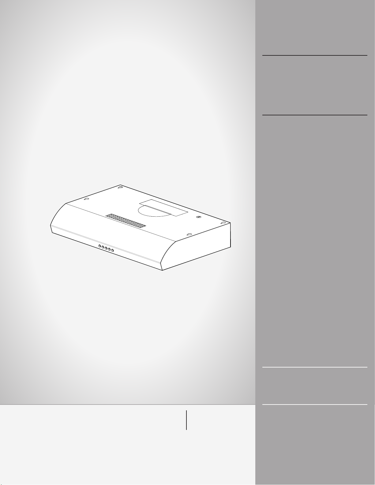
Models: ENM230S1
ENM236S1
READ AND SAVE THESE
INSTRUCTIONS
LISEZ CES
INSTRUCTIONS ET
CONSERVEZ-LES
LEA Y CONSERVE
ESTAS INSTRUCCIONES
LIB0138588
Printed in Mexico
10/17
1
Page 2

ENGLISH
Contents
Important safety notice................................................................................................................................................................................................. 3
Electrical & installation requirements ................................................................................................................................................................ 4
Before installing the hood ...................................................................................................................................................................................... 4
Dimensions and clearances......................................................................................................................................................................................... 4
List of materials................................................................................................................................................................................................................. 5
Parts supplied .............................................................................................................................................................................................................. 5
Parts not supplied ...................................................................................................................................................................................................... 5
Ducting options and examples.................................................................................................................................................................................. 6
Installation ......................................................................................................................................................................................................................... 7
Electrical connection................................................................................................................................................................................................ 8
Complete the installation........................................................................................................................................................................................ 9
Description of the hood................................................................................................................................................................................................. 9
Control.................................................................................................................................................................................................................................. 9
Maintenance ...................................................................................................................................................................................................................... 10
Warranty ........................................................................................................................................................................................................................... 11
APPROVED FOR RESIDENTIAL APPLIANCES
FOR RESIDENTIAL USE ONLY
READ AND SAVE THESE INSTRUCTIONS
PLEASE READ ENTIRE INSTRUCTIONS BEFORE PROCEEDING.
INSTALLATION MUST COMPLY WITH ALL LOCAL CODES.
IMPORTANT: Save these Instructions for the Local Electrical Inspector’s use.
INSTALLER: Please leave these Instructions with this unit for the owner.
OWNER: Please retain these instructions for future reference.
Safety Warning: Turn o power circuit at service panel and lock out panel, before wiring this appliance.
Requirement: 120 V AC, 60 Hz. 15 or 20 A Branch Circuit.
2
Page 3

IMPORTANT SAFETY NOTICE
I
I CAUTION
FOR GENERAL VENTILATING USE ONLY. DO NOT USE TO
EXHAUST HAZARDOUS OR EXPLOSIVE MATERIALS OR
VAPOURS.
I WARNING
TO REDUCE THE RISK OF FIRE, ELECTRIC SHOCK, OR
INJURY TO PERSONS, OBSERVE THE FOLLOWING:
A. Use this unit only in the manner intended by the
manufacturer. If you have questions, contact the
manufacturer.
B. Before servicing or cleaning the unit, switch power o
at service panel and lock service panel disconnecting
means to prevent power from being switched on
accidentally.
When the service disconnecting means cannot be
locked, securely fasten a prominent warning device,
such as a tag, to the service panel.
C. Installation work and electrical wiring must be done by
qualified person(s) in accordance with all applicable
codes & standards, including fire-rated construction.
D. Sucient air is needed for proper combustion and
exhausting of gases through the flue (Chimney) of fuel
burning equipment to prevent back- drafting.
Follow the heating equipment manufacturers guideline
and safety standards such as those published by the
national fire protection association (NFPA), the american
society for heating, refrigeration and air conditioning
engineers (ASHRAE), and the local code authorities.
E. When cutting or drilling into wall or ceiling, do not
damage electrical wiring and other hidden utilities.
F. Ducted systems must always be vented to the outdoors.
I CAUTION
To reduce risk of fire and to properly exhaust air, be sure to
duct air outside - do not vent exhaust air into spaces within
walls, ceilings, attics, crawl spaces, or garages.
I WARNING
TO REDUCE THE RISK OF FIRE, USE ONLY METAL DUCT
WORK.
I WARNING
TO REDUCE THE RISK OF A RANGE TOP GREASE FIRE.
a) Never leave surface units unattended at high settings.
Boilovers cause smoking and greasy spillovers that may
ignite. Heat oils slowly on low or medium settings.
b) Always turn hood ON when cooking at high heat or when
flambeing food (I.e. Crepes Suzette, Cherries Jubilee,
Peppercorn Beef Flambe’).
c) Clean ventilating fans frequently. Grease should not be
allowed to accumulate on fan or filter.
d) Use proper pan size. Always use cookware appropriate
for the size of the surface element.
I WARNING
TO REDUCE THE RISK OF INJURY TO PERSONS, IN THE
EVENT OF A RANGE TOP GREASE FIRE, OBSERVE THE
FOLLOWING:
a) SMOTHER FLAMES with a close-fitting lid, cookie sheet,
or other metal tray, then turn o the gas burner or the
electric element. BE CAREFUL TO PREVENT BURNS. If the
flames do not go out immediately, EVACUATE AND CALL
THE FIRE DEPARTMENT.
b) NEVER PICK UP A FLAMING PAN - you may be burned.
c) DO NOT USE WATER, including wet dishcloths or towels -
a violent steam explosion will result.
d) Use an extinguisher ONLY if:
1) You know you have a class ABC extinguisher, and
you already know how to operate it.
2) The fire is small and contained in the area where it
started.
3) The fire department is being called.
4) You can fight the fire with your back to an exit.
e) Ducted fans must always be vented to the outdoor.
a
Based on “Kitchen Fire Safety Tips” published by NFPA.
Install this hood in accordance with all requirements specified.
I WARNING
To reduce the risk of fire or electric shock, do not use this
hood with any external solid state speed control device.
3
Page 4
ELECTRICAL & INSTALLATION REQUIREMENTS
IMPORTANT
Observe all governing codes and ordinances.
It is the customer’s responsibility:
• To contact a qualified electrical installer.
• To assure that the electrical installation is adequate and in
conformance with National Electrical Code, ANSI/NFPA 70
— latest edition*, or CSA Standards C22.1-94, Canadian
Electrical Code, Part 1 and C22.2 No.0-M91-latest edition**
and all local codes and ordinances.
• If codes permit and a separate ground wire is used, it is
recommended that a qualified electrician determine that
the ground path is adequate.
• Do not ground to a gas pipe.
• Check with a qualified electrician if you are not sure range
hood is properly grounded.
• Do not have a fuse in the neutral or ground circuit.
IMPORTANT
• Save Installation Instructions for electrical inspector’s use.
• The range hood must be connected with copper wire only.
• The range hood should be connected directly to the fused
disconnect (Or circuit breaker) box through metal
electrical conduit.
• Wire sizes must conform to the requirements of the
National Electrical Code ANSI/NFPA 70 — latest edition*,
or CSA Standards C22.1-94, Canadian Electrical Code Part
1 and C22.2 No. 0-M91 - latest edition** and all local codes
and ordinances.
• A U.L.- or C.S.A.-listed conduit connector must be
provided at each end of the power supply conduit (at the
range hood and at the junction box).
Copies of the standards listed may be obtained from:
* National Fire Protection Association Batterymarch Park Quincy,
Massachusetts 02269
** CSA International 8501 East Pleasant Valley Road Cleveland,
Ohio 44131-5575
BEFORE INSTALLING THE HOOD
1 For the most ecient air flow exhaust, use a straight run
or as few elbows as possible.
CAUTION: Vent unit to outside of building, only.
2 At least two people are necessary for installation.
3 Fittings material is provided to secure the hood to most
types of walls/ceilings, consult a Qualified Installer,
check if they perfectly fit with your cabinet/wall.
4 Do not use flex ducting.
5 COLD WEATHER installations should have an additional
backdraft damper installed to minimize backward cold air
flow and a nonmetallic thermal break to minimize
conduction of outside temperatures as part of the
ductwork. The damper should be on the cold air side of
the thermal break.
The break should be as close as possible to where the
ducting enters the heated portion of the house.
6 Make up air: Local building codes may require the use of
Make-Up Air Systems when using Ducted Ventilation
Systems greater than specified CFM of air movement.
The specified CFM varies from locale to locale. Consult
your HVAC professional for specific requirements in your
area.
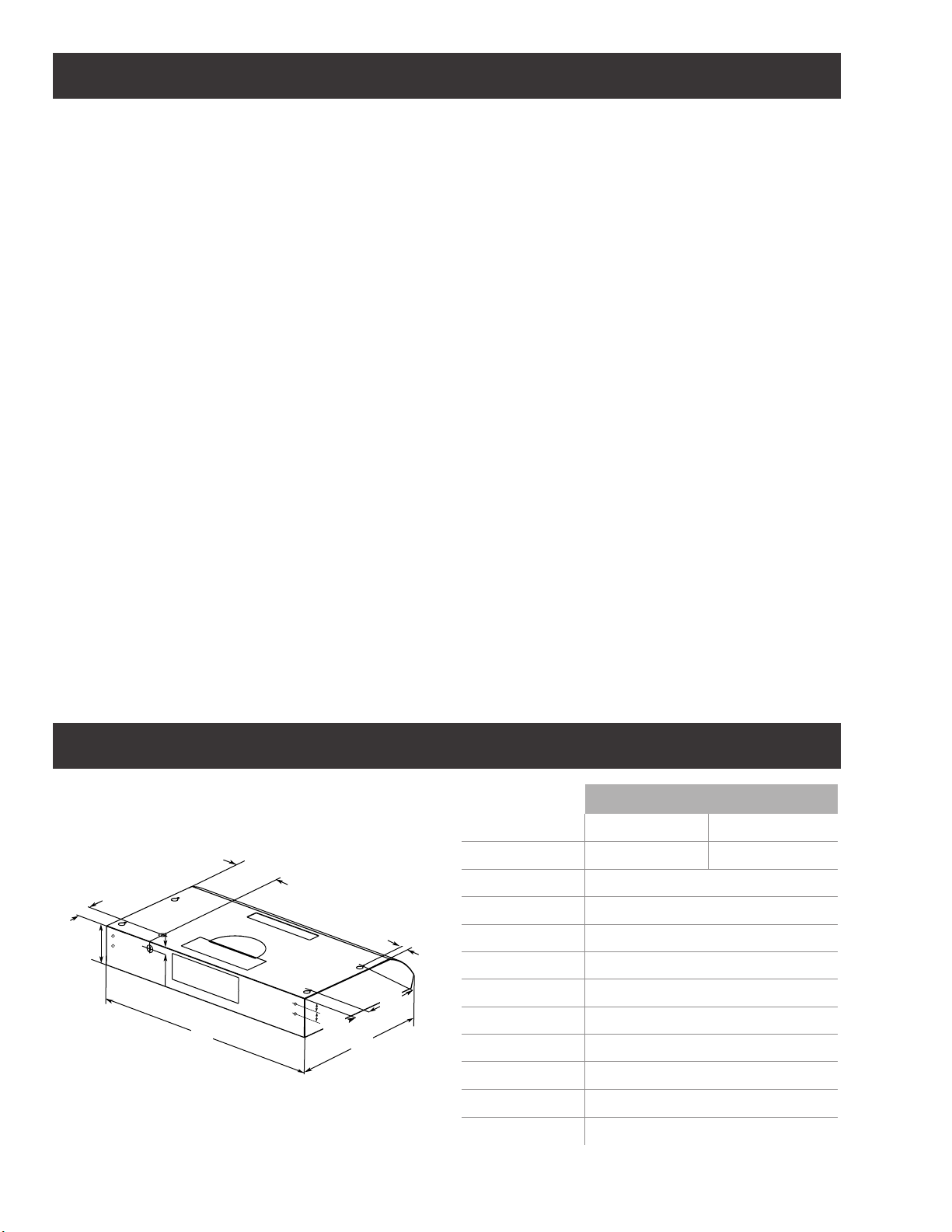
DIMENSIONS AND CLEARANCES
G
H
C
I
J
A
4
K
Models
ENM230S1 ENM236S1
A 30″ (76.2 cm) 36″ (91.4 cm)
B 185⁄8″ (47.3 cm)
C 415⁄16″ (12.5 cm)
F
E
D
B
D 11⁄2″ (3.8 cm)
E 9″ (22.9 cm)
F 1″ (2.5 cm)
G 69⁄16″ (16.7 cm)
H 115⁄16″ (5 cm)
I
J 11⁄16″ (2.6 cm)
K 17⁄16″ (3.6 cm)
7
⁄8” (2.2 cm)
Page 5
LIST OF MATERIALS
Removing the packaging.
I CAUTION
Remove carton carefully, Wear gloves to protect against sharp edges.
I WARNING
Remove the protective film covering the product before putting into operation.
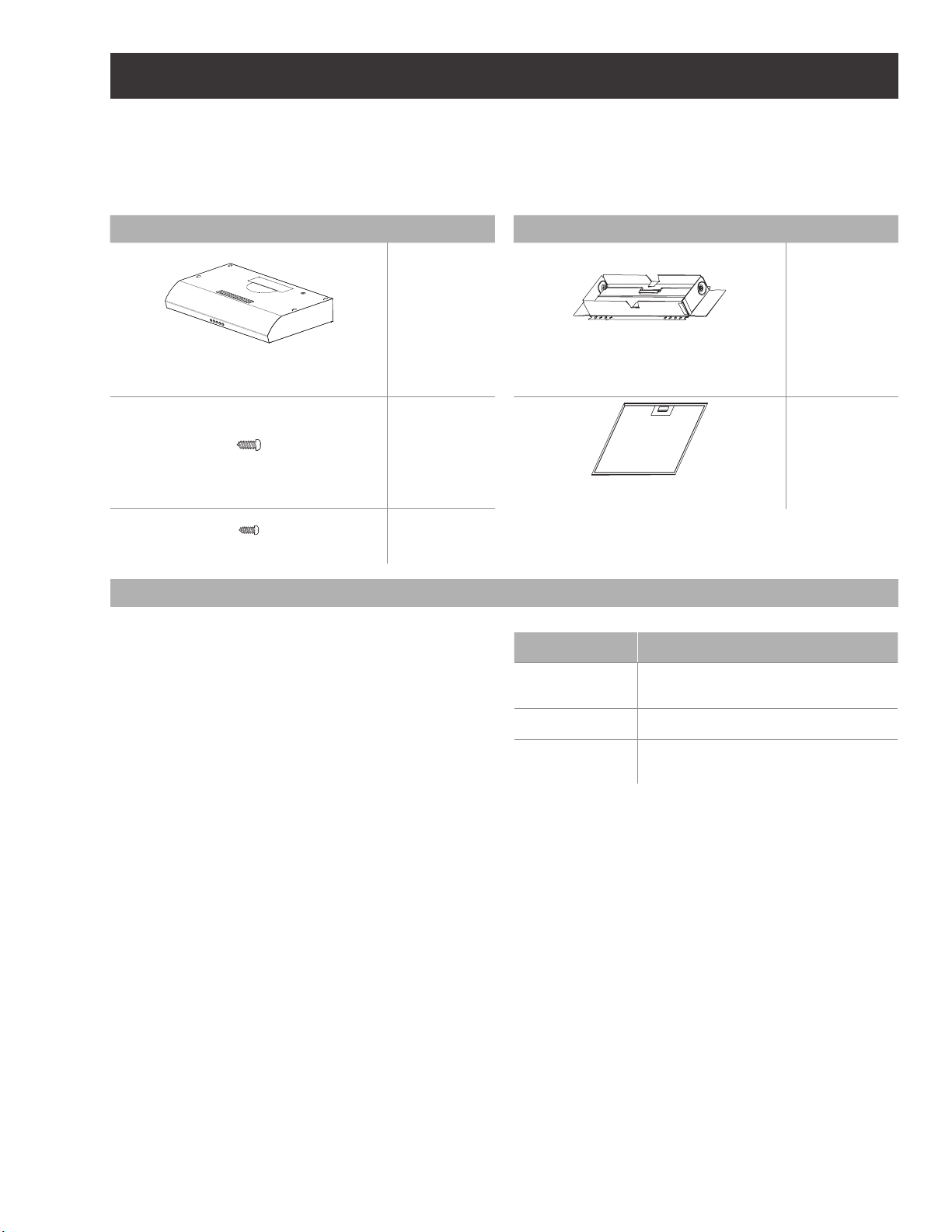
Supplied Part Pieces Supplied Part Pieces
Hood assembly and
LED lamps already installed
Tools/Materials required
• Drill
• 11⁄4” (3.0 cm) drill bit
• 1⁄8” (3.0 mm) drill bit for pilot holes
• Pencil
• Wire stripper or utility knife
• Tape measure or ruler
• Caulking gun and weatherproof caulking compound
• Saber or keyhole saw
• Metal snips
• Screwdrivers:
- Phillips
- Flat-blade
4.5x13 mm
3.5x6.5 mm
1
4
2
Parts no supplied
Optional accessories and consumable parts
Rectangular duct 31⁄4” x 10” (8.3 x 25.4 cm)
with back draft damper
KIT # Part
Recirculating Kit KIT0140997
7” Round Kit KIT02722
7” Round Back
Draft Damper Kit
Grease filter
KIT02723
1
1
5
Page 6
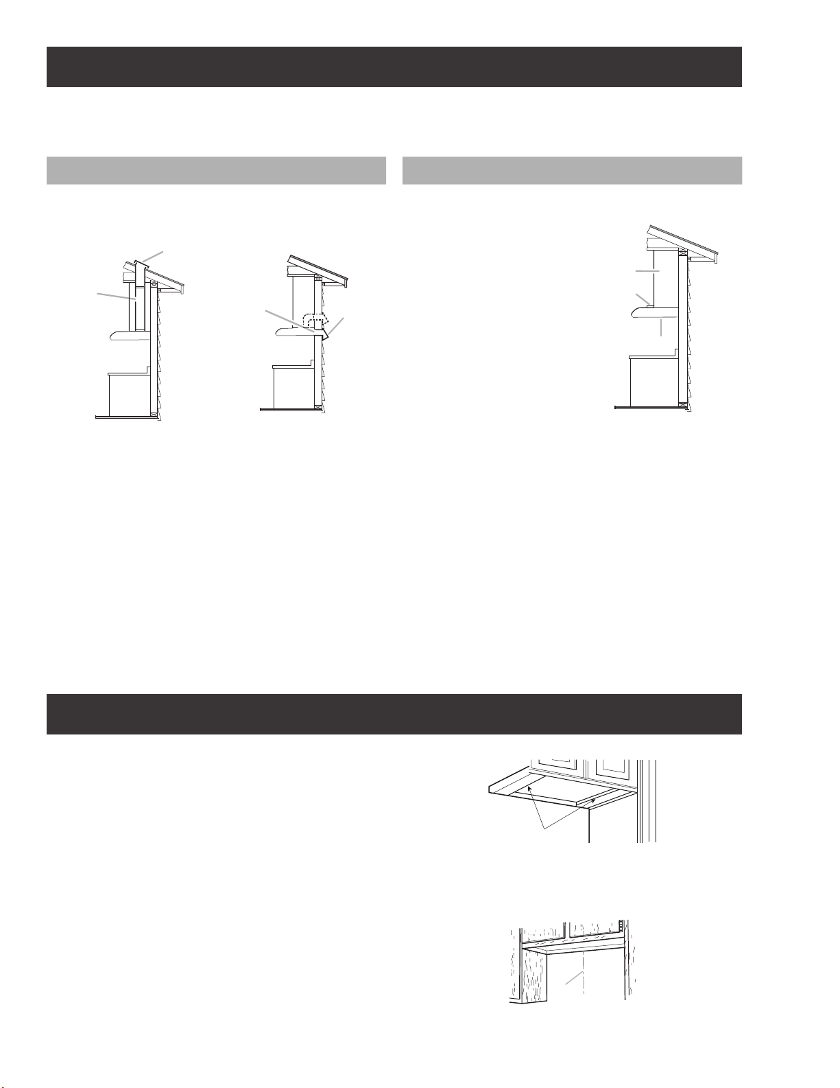
Ducting Options
Closely follow the instructions set out in this manual.
All responsability, for any eventual inconveniences, damages or fires caused by not complying with the instructions in this manual,
is declined.
Ducting version Ductless (Recirculating)
a) 3
⁄4” x 10” (8.3 x 25.4 cm) rectangular vent through the roof/wall (purchased
separately).
b) Roof/wall cap (purchased separately)
B
A
Roof Venting Wall Venting
A
B
In cases where it should not
be possible to discharge
cooking fumes and vapour
to the outside, purchase
the Ductless Recirculating
Kit.
For ductless (Recirculating)
version only.
a) Charcoal filter
b) Recirculation cover plate
c) Cabinet
C
B
A
Preparation
Do not cut a joist or stud unless absolutely necessary. If a joist
or stud must be cut, then a supporting frame must be
constructed.
Fittings material is provided to secure the hood to most types
of walls/ceilings.
However, a qualified technician must verify suitability of the
materials in accordance with the type of wall/ceiling.
Before making cutouts, make sure there is proper clearance
within the ceiling or wall for exhaust vent.
Prepare Location
NOTE: It is recommended that the vent system be installed
before hood is installed. Before making cutouts, make sure
there is proper clearance within the ceiling or wall for exhaust
vent.
1 Disconnect power.
2 Depending on your model, determine which venting
method to use: roof, wall or recirculating.
3 Select a flat surface for assembling the range hood. Place
covering over that surface.
Lift the range hood and set it upside down onto covered
surface.
For recessed bottom cabinet only
1 If the cabinets have front, side or back trim, make 2 wood
shims the width of the trim and attach them to the cabinet
bottom recess on both sides. See the diagramas for marking
locations.
IMPORTANT: Align the wood filler strips so that they
completely cover the recessed bottom cabinet.
Recommended installation height:
Hood installation height above cooktop is the users preference.
The lower the hood is above the cooktop, the more ecient
the capturing of cooking odors, grease and smoke.
I CAUTION
FOR GAS RANGES INSTALLATION: MOUNT THIS HOOD SO
THAT THE BOTTOM IS NOT LESS THAN 27” (68.6 CM).
FOR ELECTRIC RANGES INSTALLATION: MOUNT THIS HOOD
SO THAT THE BOTTOM IS NOT LESS THAN 24” (61 CM)
AND NOT MORE THAT 30” (76.2 CM) ABOVE THE COOKING
SURFACE.
Check your ceiling height and the hood height maximum
before you select your hood.
Wood shims
Determine Wiring Hole Location
Cut only one 11⁄4” (3.2 cm) diameter wiring access hole.
1 Determine and clearly mark a vertical centerline on the
wall and cabinet in the area the vent opening will be made.
A
A. Centerline
6
Page 7
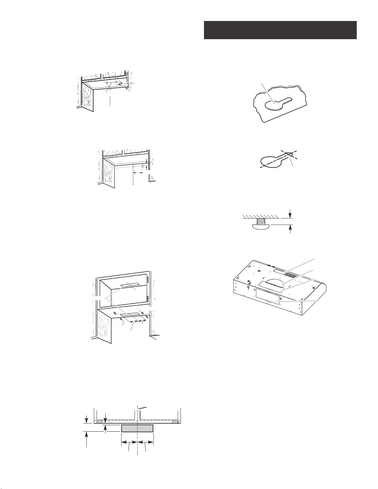
To wire through top:
2 Mark a line 83⁄8” (21.3 cm) from the right of the centerline
on the underside of the cabinet. For 12” (30.5 cm) deep
cabinets, mark the point on this line that is 2” (5.1 cm)
from the back wall. For 15” (38.1 cm) deep cabinets, mark
the point on this line that is 5” (12.7 cm) from the back
wall. Drill a 1¼” (3.2 cm) diameter hole through the cabinet
at this point.
Installation
• Lift the range hood up under cabinet and determine final
location by centering beneath cabinet. Mark on the
underside of cabinet the location of the 4 keyhole
mounting slots on the range hood. Set range hood aside
on a covered surface.
A
83⁄8” (21.3 cm)
Centerline
*2” (5.1 cm) for 12”
(30.5 cm) deep cabinets
*5” (12.7 cm) for 15”
(38.1 cm) deep cabinets
*from wall, not cabinet frame
To wire through wall:
1 Mark a line 83⁄8” (21.3 cm) from the right of the centerline
on the underside of the wall. Mark the point on this line that
is 7⁄8” (2.2 cm) from the underside of the cabinet. Drill a 11⁄4”
(3.2 cm) diameter hole through the rear wall at this point.
7
⁄8” (2.2 cm)
83⁄8”
(21.3 cm)
Centerline
Cut Openings for 3¼” x 10” (8.3 cm x 25.4 cm)
Rectangular Vent System
Roof Venting
To make a 41⁄4” x 10½” (10.8 cm x 26.7 cm) rectangular cutout
on the underside of cabinet top and bottom:
1 Mark lines 1⁄2” (1.3 cm) and 43⁄4” (12.1 cm) from the back wall
on the centerline of the underside of cabinet.
2 Mark lines 5¼” (13.3 cm) to the right and left of the center-
line on the underside of cabinet.
3 Use saber or keyhole saw to cut a rectangular opening for
vent.
4 Repeat steps 1-3 for the underside of the top of the cabinet.
A. Keyhole slot
• Use ⁄8” (3 mm) drill bit and drill 4 pilot holes as shown.
A
A. Drill pilot hole
• Install the 4 - 4.5 mm x 13 mm mounting screws in pilot
holes. Leave about ⁄4” (6.4 mm) space between screw
heads and cabinet to slide range hood into place.
1
⁄4″
(6.4 mm)
• Remove transition knockouts depending on the selected
venting method.
D
C
A
Cabinet cutouts
1” (2.5 cm)
1
⁄4”
5
(13.3 cm)
1
⁄4”
5
(13.3 cm)
5”
(12.7 cm)
*From wall, not cabinet frame
Wall Venting
To make a 41⁄4” x 10½” (10.8 cm x 26.7 cm) rectangle in the wall:
1 Make 2 lines by measuring 1⁄8” (0.3 cm) and 41⁄16” (10.3 cm)
down from underside of cabinet and mark on the centerline
on the back wall.
2 Mark lines 5¼” (13.3 cm) to the right and left of the centerline
on the wall.
3 Use saber or keyhole saw to cut a rectangular opening in
the wall for the vent.
1
⁄4”
4
(10.8 cm)
1
⁄8”
(0.3 cm)
Cabinet
front
1
5
⁄4”
(13.3 cm)
51⁄4”
(13.3 cm)
Centerline
B
A. Top rectangular vent knockout
B. Rear rectangular vent knockout
C. Round vent knockout
D. Recirculation cover plate
Top venting outlet (exit through the wall or the roof):
For rectangular vent system installations, remove the top
rectangular knockout.
NOTE: For round vent system installations, remove the top
round knockout.
Rear venting outlet (exit through the wall):
Remove the rear rectangular knockout.
Non-ducted (recirculating) installations - No vent attachments.
Remove the two screws from the recirculation cover plate and
set it aside. See the Recirculating installations section.
• Remove metal grease filters. See the “Range Hood Care”
section. First remove the bracket and then the lateral panels.
NOTE: You will have 3 1⁄4” x 10” (8.3 x 25.4 cm) rectangular
vent transition inside your range hood. Remove the 3-1⁄4” x
10” (8.3 x 25.4 cm) rectangular vent transition inside your
range hood.
7
Page 8
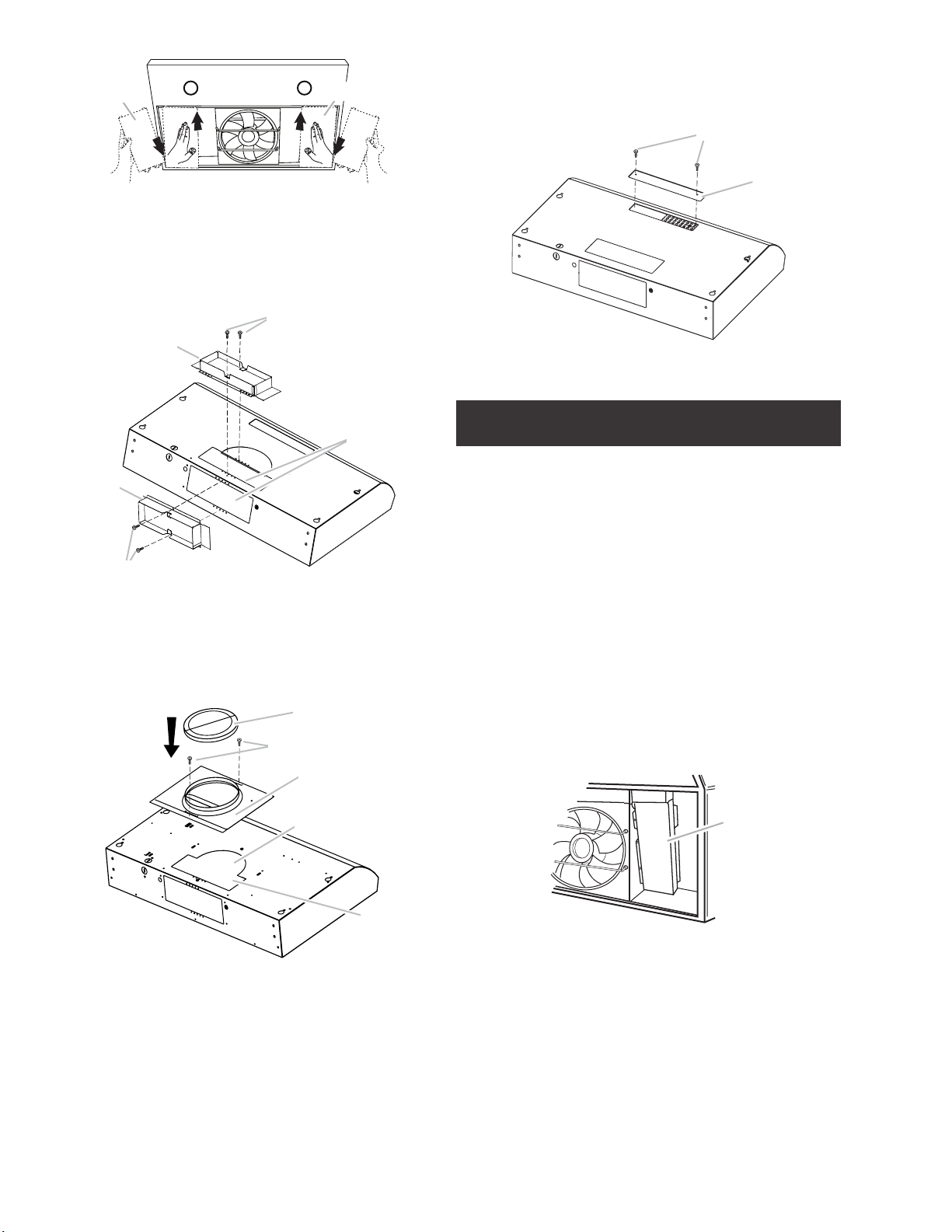
Non-ducted (recirculating) installations - No vent attachments.
A
A
It requires the removal of the recirculation cover plate.
Remove the two screws from the recirculation cover plate and
remove.
A
A. Lateral panels
• Install 31⁄4 x 10” (8.3 x 25.4 cm) vent connector, depending
on the vent system installation.
NOTE: The 31⁄4 x 10” (8.3 x 25.4 cm) rectangular vent connector
can be installed up to 1” (2.5 cm) on either side of the hood
center to accommodate o center ductwork.
B
A
C
D
B
A. Vertical connector
B. 6.5 x 9.5 mm screws
C. Vent knockouts
D. Horizontal connector
• For round installation: Install 7” (17.8 cm) round vent
mounting plate and damper (purchase as an accesory).
A
B
A. Screws (2)
B. Recirculation cover plate
Electrical Connection
I WARNING
Electrical Shock Hazard
I WARNING
Turn o power circuit at the service panel before wiring this
unit. 120 VAC, 15 or 20 Amp circuit required.
ELECTRICAL GROUNDING INSTRUCTIONS
THIS APPLIANCE IS FITTED WITH AN ELECTRICAL JUNCTION
BOX WITH 3 WIRES, ONE OF WHICH (GREEN/YELLOW)
SERVES TO GROUND THE APPLIANCE. TO PROTECT YOU
AGAINST ELECTRIC SHOCK, THE GREEN AND YELLOW WIRE
MUST BE CONNECTED TO THE GROUNDING WIRE IN YOUR
HOME ELECTRICAL SYSTEM, AND IT MUST UNDER NO
CIRCUMSTANCES BE CUT OR REMOVED.
Failure to do so can result in death or electrical shock.
B
C
D
E
A. 7” (17.8 cm) round damper
B. Sheet metal screws
C. 7” (17.8 cm) round vent mounting plate
D. Round vent knockout
E. Rectangular vent knockout
• If a vent damper is installed with a wall cap with damper,
check to make sure they do not interfere with each other.
Remove the vent connector damper flap if they interfere.
• Remove the knockout and the Junction box cover and
install the conduit connector (cULus listed) in junction box.
A
A. Terminal box cover
8
Page 9

• Run 3 wires; black, white and green ,according to the
National Electrical Code and local codes and ordinances,
in 1⁄2” conduit from service panel to junction box.
Description of the Hood
G
C
A
B
A. White wires
B. Black wires
C. UL listed wire connector
D. Green (or bare) ground wire
D
E. Home power supply cable
or power cord accessory kit
F. UL listed or CSA approved
½” strain relief
G. Green ground screw
E
F
• Connect black wire from service panel to black or red in
junction box, white to white and green to green-yellow.
• Close and secure junction box cover.
Complete Installation
• Lift the hood into final position. Feed enough electrical
wire through the ½” UL listed or CSA approved strain relief
to make connections in the terminal box. Tighten the strain
relief screws.
• Position the range hood so that the large end of the keyhole
slots are over the mounting screws. Then push the hood
toward the wall so that the screws are in the neck of the
slots.
3
1
3
1. Control
2. LED lights
3. Lateral panels
2
4
5
4. Bracket
5. Grease filter
6. Grease filter handle
6
Controls
1. Light On/O button
2. Blower On/O button
3. Blower speed minimum button
4. Blower speed medium button
5. Blower speed maximum button
NOTE: Control buttons will light up when range hood is On.
Operating the light
The Light On/O button (1) controls both lights. Press once
for On and again for O.
A
B
A. Mounting screws (4)
B. Security screws
• Tighten the mounting screws, making sure the screws are
in the narrow neck of slots.
• Connect ventwork to hood. Seal joints with clamps to
make secure and airtight.
• Check that back draft dampers work properly.
• Replace filters. See the “Range Hood Care”.
Check operation of the hood.
If range hood does not operate:
• Check that the circuit breaker is not tripped or the house
fuse blown.
• Disconnect power supply. Check that wiring is correct.
To get the most efficient use from your new range hood, read
the “Use and Care Information” section.
Keep your Installation Instructions and Use and Care Guide
close to range hood for easy reference.
Operating the blower
The Blower On/O button (2) turns the blower On or O.
The Blower Speed buttons (3, 4 and 5) set the desired speed
and control the sound level for quiet operation. The speed
can be changed anytime during fan operation by pressing the
desired blower speed button.
1 To turn the blower On, press the Blower On/O button (2)
and the desired speed button (3, 4 or 5).
2 To turn the blower O, press the Blower On/O button (2).
Any of the 3 blower speed buttons can be in the On position
at the same time. The blower will operate at the highest speed
button that is pushed in. For lower blower speeds, the higher
speed buttons must not be pushed in.
9
Page 10

Range Hood Care
Cleaning
Do not spray cleaners directly to the control while cleaning the
Hood. The cooker hood should be cleaned regularly (at least
with the same frequency with which you carry out maintenance
of the fat filters) internally and externally. Clean using the
cloth dampened with neutral liquid detergent. Do not use
abrasive products.
DO NOT USE ALCOHOL!
I WARNING:
Failure to carry out the basic cleaning recommendations of the
cooker hood and replacement of the filters may cause fire risks.
Therefore, we recommend oserving these instructions.
The manufacturer declines all responsibility for any damage to
the motor or any fire damage linked to inappropriate maintenance
or failure to observe the above safety recommendations.
Grease filter
Traps cooking grease particles.
This must be cleaned once a month using non aggressive
detergents, either by hand or in the dishwasher, which must
be set to a low temperature and a short cycle. When washed
in a dishwasher, the grease filter may discolour slightly, but
this does not affect its filtering capacity.
To remove the grease filter
1 Remove the grease filter bracket.
A
Charcoal filter
If the model is not vented to the outside, the air will be
recirculated through disposable charcoal filter that help remove
smoke and odors.
The charcoal filter cannot be cleaned.
It must be replaced.
The charcoal filter is clipped inside of the metal grease filter
The charcoal filter should be replaced every 4-6 months
(depending on hood usage).
NOTE: DO NOT rinse, or put charcoal filter in an automatic
dishwasher.
NOTE: Charcoal filter is not included with the hood.
It must be ordered from your supplier.
Order the needed kit specifying your hood model and width
size.
Charcoal filter placement (Recirculating accessories)
Fit the charcoal filter mattress on the upper side of the grease
filter.
Use provided rods to fix it in place.
NOTE: Place each rod into the hole in A side and then into the
next hole in B side of the charcoal filter as the image below.
Rod
Holes in
A Side
Charcoal filter
B
A. Bracket
B. Grease filter bracket screws (2)
2 Pull the spring release handle to remove the grease filter.
A
3 Reinstall the filter by placing the back edge in the channel
at rear of hood.
4 Replace the bracket using the screws that were previously
removed in step 1.
Replacing a LED Lamp
The LED lights are replaceable by a service technician only.
See the service contact information in this page below.
Holes in
B Side
10
Page 11

ELICA North America
TWO-YEARS LIMITED WARRANTY
TO OBTAIN SERVICE UNDER WARRANTY
Owner must present proof of original purchase date. Please keep a copy of your dated proof of purchase (sales slip) in
order to obtain service under warranty.
PARTS AND SERVICE WARRANTY
For the period of two (2) years from the date of the original purchase, Elica will provide free of charge, non consumable
parts or components that failed due to manufacturing defects. During these two (2) years limited warranty, Elica will also
provide free of charge, all labor and in-home service to replace any defective parts.
WHAT IS NOT COVERED
• Damage or failure to the product caused by accident or act of God, such as, flood, fire or earthquake.
• Damage or failure caused by modification of the product or use of non-genuine parts.
• Damage or failure to the product caused during delivery, handling or installation.
• Damage or failure to the product caused by operator abuse.
• Damage or failure to the product caused by dwelling fuse replacement or resetting of circuit breakers.
• Damage or failure caused by use of product in a commercial application.
• Service trips to dwelling to provide use or installation guidance.
• Light bulbs, metal or carbon filters and any other consumable part.
• Normal wear of finish.
• Wear to finish due to operator abuse, improper maintenance, use of corrosive or abrasive cleaning products/pads and
oven cleaner products.
WHO IS COVERED
This warranty is extended to the original purchaser for products purchased for ordinary residential use in North America
(Including the United States, Guam, Puerto Rico, US Virgin Islands & Canada).
This warranty is non-transferable and applies only to the original purchaser and does not extend to subsequent owners of
the product. This warranty is made expressly in lieu of all other warranties, expressed or implied, including, but not limited
to any implied warranty of merchantability or fitness for a particular purpose and all other obligations on the part of Elica
North America, provided, however, that if the disclaimer of implied warranties is ineective under applicable law, the duration of any implied warranty arising by operation of law shall be limited to two (2) years from the date of original purchase
at retail or such longer period as may be required by applicable law.
Th
is warranty does not cover any special, incidental and/or consequential damages, nor loss of profits, suered by the
original purchaser, its customers and/or the users of the Products.
WHO TO CONTACT
To obtain service under warranty or for any service related question:
• Elica North America Service, call at 1 888 732 8018
• For Eastern Canada, call AGI Services at 1 888 651 2534 Ask for the service department
• elica@servicepower.com
Page 12

FRANÇAIS
Table des matières
Avis de sécurité important ......................................................................................................................................................................................... 13
Exigences électriques et d’installation ............................................................................................................................................................. 14
Avant d’installer la hotte ........................................................................................................................................................................................ 14
Dimensions du produit ................................................................................................................................................................................................. 14
Liste des pièces ............................................................................................................................................................................................................... 15
Pièces fournies ........................................................................................................................................................................................................... 15
Pièces non fournies .................................................................................................................................................................................................. 15
Méthodes d’evacuation ................................................................................................................................................................................................. 16
Installation ......................................................................................................................................................................................................................... 17
Electrical connection................................................................................................................................................................................................ 19
Achever l’installation ................................................................................................................................................................................................ 19
Description de la hotte ................................................................................................................................................................................................ 20
Commandes ..................................................................................................................................................................................................................... 20
Entretien ............................................................................................................................................................................................................................ 20
Garantie .............................................................................................................................................................................................................................. 22
APPROUVÉ POUR LES APPAREILS DE TYPE RÉSIDENTIEL
POUR UNE UTILISATION RÉSIDENTIELLE SEULEMENT
LISEZ CES INSTRUCTIONS ET CONSERVEZ-LES
VEUILLEZ LIRE CES INSTRUCTIONS AU COMPLET AVANT DE COMMENCER.
L’INSTALLATION DE L’APPAREIL DOIT RESPECTER TOUS LES CODES EN VIGUEUR.
IMPORTANT : Conservez ces instructions afin de pouvoir les remettre à l’inspecteur-électricien de votre région.
INSTALLATEUR : Veuillez laisser ces instructions avec l’appareil pour le propriétaire.
PROPRIÉTAIRE : Veuillez conserver ces instructions pour pouvoir vous y référer plus tard.
Avertissement de sécurité : Coupez l’alimentation du circuit dans le panneau électrique et verrouillez le
panneau avant de raccorder les fils de cet appareil.
Exigence : 120 V c.a., 60 Hz circuit de dérivation de 15 V c.a., 20 Hz, de 15 ou 20 A.
12
Page 13

AVIS DE SÉCURITÉ IMPORTANT
I
I ATTENTION
UTILISER CET APPAREIL À DES FINS DE VENTILATION
GÉNÉRALE SEULEMENT. NE PAS UTILISER CET APPAREIL
POUR ÉVACUER DES MATÉRIAUX OU DES VAPEURS
DANGEREUX OU EXPLOSIFS.
I AVERTISSEMENT
POUR RÉDUIRE LES RISQUES D’INCENDIE, DE CHOC
ÉLECTRIQUE ET DE BLESSURE, RESPECTER LES DIRECTIVES
SUIVANTES:
A. Utiliser cet appareil uniquement aux fins prévues par le
fabricant. Si vous avez des questions à propos de l’appareil,
communiquez avec le fabricant.
B. Avant de faire l’entretien de l’appareil ou de le nettoyer,
coupez l’alimentation dans le panneau électrique et
verrouillez le panneau en bloquant le dispositif permettant
d’empêcher d’activer l’alimentation accidentellement. S’il
n’est pas possible de verrouiller l’accès au panneau, fixez
une étiquette très voyante au panneau électrique.
C. Une personne qualifiée doit eectuer l’installation et le
câblage des fils électriques en conformité avec tous les
codes et toutes les normes, y compris la cote de résistance
au feu.
D. Il est important de prévoir susamment d’air pour assurer
une bonne combustion de l’équipement de chaue et l’évacuation adéquates des gaz par le conduit de cheminé afin
de prévenir les refoulements d’air. Respectez les directives
et les normes de sécurité des fabricants de l’équipement
de chauage, comme celles publiées par la National Fire
Protection Association (NFPA), la American Society for
Heating, Refrigeration and Air Conditioning Engineers
(ASHRAE) et le code des autorités de votre région.
E. Au moment de couper ou de percer un mur ou un plafond,
assurez-vous de ne pas endommager la filerie électrique
ou tout autre accès à un service publique.
F. Il faut toujours évacuer à l’extérieur les systèmes conduit.
I ATTENTION
Pour réduire les risques d’incendie et évacuer l’air correctement,
assurez-vous que le conduit mène à l’extérieur; il ne faut pas
évacuer l’air dans l’espace entre les murs, dans les plafonds, dans
les greniers, les vides sanitaires ou les garages.
I AVERTISSEMENT
POUR RÉDUIRE DES RISQUES D’INCENDIE, UTILISEZ
UNIQUEMENT DES CONDUITS EN MÉTAL.
Installez cette hotte en respectant toutes les exigences
mentionnées.
I AVERTISSEMENT
POUR RÉDUIRE LES RISQUES D’INCENDIE DE GRAISSE SUR
LES CUISINIÈRES.
a) Ne laissez jamais la cuisinière sans surveillance lorsqu’elle
est réglée à une haute température. Les débordements par
bouillonnement causent de la fumée et des débordements
de gras qui peuvent s’enflammer. Faites chauer l’huile
lentement, à une température basse ou moyenne.
b) Faites toujours fonctionner la hotte lorsque vous utilisez
la cuisinière à une haute température ou que vous faites
flamber des aliments (P. ex.: crêpes Suzette, cerises
jubilées, boeuf au poivre flambé).
c) Nettoyez les hélices de ventilation fréquemment. Il ne faut
pas que la graisse s’accumule sur les filres ou les hélices.
d) Utilisez le bon format de casserole. Utilisez toujours un
chaudron de taille approprié à l’élément de la cuisinière.
e) Convient pour utilisation dans la zone de cuisson domestique.
I AVERTISSEMENT
POUR ÉVITER DE BLESSER QUELQU’UN LORS D’UN
INCENDIE DE GRAISSE SUR LA CUISINIÈRE, SUIVRE LES
CONSEILS SUIVANTS:
a) ÉTOUFFER LES FLAMMES avec un couvercle aux
dimensions de la taque de cuisson, une tôle à biscuit ou
tout autre plateau métallique, puis couper le gaz ou
l’alimentation électrique de la cuisinière. FAIRE ATTENTION
A NE PAS SE BRÛLER. Si les flammes ne s’éteignent pas
immédiatement, QUITTER LA PIÈCE ET APPELER LES
POMPIERS.
b) NE JAMAIS PRENDRE EN MAIN UNE CASSEROLE N FEU,
vous pourriez vous blesser.
c) NE PAS UTILISER D’EAU, y compris les essuies de vaisselle
ou les serviettes humides – une violente explosion due à la
vapeur formée pourrait survenir.
d) Utiliser un extincteur SEULEMENT si:
1) Vous êtes sûr d’avoir un extincteur de classe ABC que
vous savez utiliser.
2) Le feu est petit et confiné à la zone où il s’est formé.
3) Les pompiers ont été appelés.
4) Vous pouvez lutter contre le feu avec une sortie
derrière vous.
e) Les ventilateurs conduits doivent toujours être évacués
vers l’extérieur.
a Recommandations tirées des conseils de sécurité en cas d’incendie de cuisine
publiés par la NFPA.
a
.
I AVERTISSEMENT
Pour réduire les risques d’incendie et de choc électrique,
n’utilisez pas cette hotte avec un contrôleur de vitesse à
semi-conducteurs.
I ATTENTION
Dispositif à commande automatique - pour réduire le risque
de Blessure Débrancher de l’alimentation électrique avant la
maintenance.
13
Page 14

EXIGENCES ÉLECTRIQUES ET D’INSTALLATION
IMPORTANT
Respectez tous les codes et les ordonnances en vigueur.
Le client a la responsabilité de :
• Contacter un électricien-installateur.
• Vérifier que l’installation électrique est adéquate et confor me avec le Code national de l’électricité, ANSI/ NFPA
70 (la plus récente édition*), ou les normes C22.1-94, Code
canadien de l’électricité, Partie 1 et C22.2 No.0-M91
(La plus récente édition**) de la CSA, ainsi que tous les
codes et les ordonnances de votre région.
• Si le code le permet et que vous utilisez un fil de mise
à la terre distinct, il est recommandé de faire vérifier le
chemin du fil par un électricien.
• Ne pas mettre l’appareil à la terre sur une conduite de gaz.
• Consultez un électricien qualifié si vous n’êtes pas
certain que la hotte est mise à la terre correctement.
• N’installez pas un fusible dans le circuit neutre ou le
circuit de mise à la terre.
IMPORTANT
• Conservez ces instructions afin de pouvoir les remettre à
l’inspecteur-électricien.
• La hotte doit être câblée uniquement à l’aide de fils de
cuivre.
• Il faut raccorder la hotte directement à une boîte à
fusible ou à un disjoncteur par l’entremise d’une
canalisation électrique en métal.
• Le calibre de fil doit être conforme aux exigences du
Code national de l’électricité, ANSI/NFPA 70 (La plus
récente édition*), ou les normes C22.1-94, Code
canadien de l’électricité, Partie 1 et C22.2 0-M91 (La
plus récente édition**) de la CSA, ainsi que tous les
codes et les ordonnances de votre région.
• Il faut prévoir un connecteur de canalisation approuvé
par l’UL ou la CSA à chaque extrémité de la canalisation
d’alimentation (À la hotte et à la boîte de jonction).
AVANT D’INSTALLER LA HOTTE
1 Pour assurer la ventilation la plus ecace possible,
installez la conduite en ligne droite ou avec le moins de
coudes possibles.
ATTENTION : La sortie de la conduite de ventilation
doit donner sur l’extérieur.
2 Deux personnes sont nécessaires pour eectuer
l’installation.
3 La quincaillerie fournie permet de fixer la hotte à la
plupart des murs et des plafonds; consultez un
installateur qualifié pour vous assurer que la
quincaillerie fournie est adaptée à votre type de mur
ou d’armoire.
4 N’utilisez pas de conduit flexible.
5 Dans le cas des endroits sujets aux TEMPÉRATURES
FROIDES, il faut installer un clapet de contre-tirage
supplémentaire afin de minimiser le retour d’air froid et
un isolant thermique non métallique afin de minimiser
la conduction de la température extérieur dans le
conduit. Il faut placer le clapet du côté de l’air froid de
l’isolant thermique.
L’isolant doit être placé le plus près possible de
l’endroit où le conduit entre dans la partie chauée de
la maison.
6 Air d’appoint : Le code du bâtiment de votre région
peut exiger l’utilisation d’un système d’air d’appoint si
vous utilisez un système de ventilation à conduit dont
le mouvement d’air dépasse un certain nombre de
CFM. Le nombre de pi3/min varie d’une région à
l’autre. Consultez un professionnel de CVC pour
connaître les exigences précises de votre région.
Vous pouvez obtenir un exemplaire des normes indiquées en vous adressant à:
* La National Fire Protection Association, Batterymarch Park Quincy,
Massachusetts, 02269
** La CSA International, 8501 East Pleasant Valley Road, Cleveland,
Ohio, 44131-5575
DIMENSIONS DU PRODUIT
G
H
C
I
A
14
Modèles
ENM230S1 ENM236S1
A 30″ (76,2 cm) 36″ (91,4 cm)
B 185⁄8″ (47,3 cm)
C 415⁄16″ (12,5 cm)
F
J
K
D
E
B
D 11⁄2″ (3,8 cm)
E 9″ (22,9 cm)
F 1″ (2,5 cm)
G 69⁄16″ (16,7 cm)
H 115⁄16″ (5 cm)
I
J 11⁄16″ (2,6 cm)
K 17⁄16″ (3,6 cm)
7
⁄8” (2,2 cm)
Page 15

LISTE DES PIÈCES
Retirer les pièces de leur emballage.
I ATTENTION
Enlever délicatement le carton, porter des gants pour se protéger des bords coupants.
I AVERTISSEMENT
Enlever le film de protection recouvrant le produit avant de commencer l’opération.
Pièces Fournies Quantité Pièces Fournies Quantité
1
Assemblage hotte avec
Outils nécessaires
• Perceuse
• Foret de 11⁄4” (3,0 cm)
• Foret de 1⁄8” (3,0 mm) pour avant-trous
• Crayon
• Pince à dénuder ou couteau utilitaire
• Ruban á mesurer ou règle
• Pistolet à calfeutrage et composé de calfeutrage résistant
aux intempéries
• Tournevis à lame plate
• Tournevis Philips
• Scie sauteuse ou scie à guichet
• Cisaille de ferblantier
lampes DEL
4,5x13 mm
3,5x6,5 mm
4
2
Pièces non fournies
Module connecteur de conduit
rectangulaire de 31⁄4” x 10” (8,3 x 25,4 cm)
Accessoires optionnel
KIT # Pièce
Kit de recyclage KIT0140997
Plaque de
montage de
conduit circulaire
de 7”
Clapet anti-reflux
rond de 7”
Filtre à graisse
KIT02722
KIT02723
1
1
15
Page 16

Méthodes d’évacuation
Suivez à la lettre les directives présentées dans ce manuel.
Le fabricant refuse toute responsabilité en ce qui a trait à tout préjudice, dommage ou incendie causé par la non observation
des directives contenues dans le présent manuel.
Version à conduit Version sans conduit (Recyclage)
a) 3
⁄4” x 10” (8.3 x 25.4 cm) rectangular vent through the roof/wall (purchased
separately).
b) Roof/wall cap (purchased separately)
B
A
Décharge à travers le toit Décharge à travers le mur
A
B
S’il s’avère impossible d’évacuer la
fumée et les vapeurs de cuisson
à l’extérieur, il est possible de
transformer la hotte en version
sans conduit (Recyclage).
Dans le cas de la version sans
conduit (à recyclage) seulement:
procurez-vous la trousse de
conversion en hotte à recyclage.
a) Filtre au charbon
b) Plaque de protection pour mode
recyclage
c) Placard
C
B
A
Préparation
Ne coupez pas une solive ou un montant à moins qu’il soit
absolument nécessaire de le faire. Si vous devez couper une
solive ou un montant, vous devez construire un cadre de soutien.
La quincaillerie fournie permet de fixer la hotte à la plupart des
murs et des plafonds.
Vous devez cependant demander à un technicien qualifié de
vérifier la solidité des matériaux selon le type de mur ou de
plafond.
Avant de couper, assurez-vous qu’il y a un dégagement susant
dans le plafond ou le mur pour passer la conduite de sortie.
Préparation de l’emplacement
REMARQUE: Il est recommandé d’installer le circuit d’évacuation
avant de procéder à l’installation de la hotte. Avant d’exécuter
les découpages, vérifier la disponibilité d’un dégagement
susant dans le plafond ou le mur pour le conduit d’évacuation.
Avant d’installer la hotte, mesurer la hauteur libre sous plafond
et la hauteur maximum disponible sous la hotte.
1 Déconnecter la source de courant électrique.
2 Déterminer la méthode d’évacuation à utiliser: décharge à
travers le mur ou le toit, ou recyclage.
3 Sélectionner une surface plane pour l’assemblage de la
hotte. Placer le matériau de protection sur cette surface.
Pour armoires encastrées uniquement
1 Si les armoires ont une garniture à l’avant, sur le côté ou
à l’arrière, réaliser 2 morceaux de bois de la largeur des
garnitures et les attacher à l’armoire encastrée sur les 2
côtés. Installer les vis pour fixer les tringles d’appui aux
emplacements indiqués.
I ATTENTION
POUR L’INSTALLATION DES CUISINIERES À GAZ: INSTALLER
CETTE HOTTE DE SORTE QUE LE REBORD INFÉRIEUR EST
À 27” (68,6 CM) AU-DESSUS DE LA SURFACE DE CUISSON.
POUR L’INSTALLATION DES CUISINIERES ÉLECTRIQUES /
INDUCTION: INSTALLER CETTE HOTTE DE SORTE QUE LE
REBORD INFÉRIEUR EST PAS MOINS DE 24” (61 CM) SUR LA
SURFACE DE CUISSON. IL EST RECOMMANDÉ D’INSTALLER
CETTE HOTTE PLUS DE 30” (76,2 CM) AU-DESSUS DE LA
SURFACE DE CUISSON. PAR POUCE (2,54 CM) SUPÉRIEURE
À 30” (76,2 CM) DIMINUERA L’EFFICACITÉ DE LA CAPTURE
DE LA FUMÉE ET DE L’HUMIDITÉ, ET LA PERFORMANCE DE
VENTILATION.
S’IL VOUS PLAÎT LIRE L’INSTALLATION POUR UNE
INSTALLATION SPÉCIFIQUE. Avant de choisir la hotte, vérifiez
la hauteur du plafond et la hauteur maximale de la hotte.
IMPORTANT: Alignez les triangles d’appui afin qu’ils
couvrent complètement l’armoire inférieure encastrée.
Tringles d’appui en bois
Déterminer l’emplacement du trou de passage du câble
Percer seulement un trou de passage de 1¼” (3,2 cm) de
diamètre pour le câblage.
1 Déterminer et tracer clairement l’axe central vertical sur
le mur et le placard dans la zone où le passage du conduit
d’évacuation sera réalisé.
16
Page 17

A
A. Axe central
3 Utiliser une scie sauteuse ou une scie à guichet pour
découper l’ouverture rectangulaire dans le mur pour le
passage du conduit d’évacuation.
Avant du
placard
Axe central
Câblage à travers le sommet du placard:
2 Tracer une ligne de distance 83⁄8” (21,3 cm) à droite de l’axe
central, sur la face inférieure du placard. Pour les placards
de 12” (30,5 cm) de profondeur, sur cette ligne, marquer le
point situé à 2” (5,1 cm) du mur arrière. Pour les placards
de 15” (38,1 cm) de profondeur, sur cette ligne, marquer le
point situé à 5” (12,7 cm) du mur arrière. Percer en ce
point un trou de 1¼” (3,2 cm) de diamètre à travers le placard.
83⁄8” (21,3 cm)
Axe central
2” (5,1 cm) pour un placard de 12” (30,5 cm)
de profond*
5” (12,7 cm) pour un placard de 15” (38,1 cm)
de profond*
*À partir du mur, et non du cadre du placard
Passage du câble à travers le mur:
1 Tracer une ligne de distance 83⁄8” (21,3 cm) à droite de l’axe
central, sur la face inférieure du placard. Sur cette ligne,
marquer le point situé à 7⁄8 “ (2,2 cm) à partir de la face
inférieure du mur. Percer en ce point un trou de 1⁄4“ (3,2 cm)
de diamètre à travers le mur arrière.
7
⁄8” (2,2 cm)
83⁄8”
(21,3 cm)
Axe central
1
⁄8”
(0,3 cm)
1
⁄4”
4
(10,8 cm)
1
5
⁄4”
(13,3 cm)
51⁄4”
(13,3 cm)
Installation
• Soulevez le capot de rangement sous l’armoire et déterminez
l’emplacement final en le centrant sous l’armoire.
• Marquez sur la partie inférieure de l’armoire l’emplacement
des 4 fentes de fixation de la serrure sur la hotte.
• Mettre la hotte de rangement sur une surface recouverte.
A
A. Trou allongé
• À l’aide d’un foret de ⁄8” (3 mm), percer 4 avant-trous tel
qu’illustré.
Découpages d’ouverture pour un système d’évacuation
rectangulaire de 3¼” x 10” (8,3 cm x 25,4 cm)
Évacuation à travers le toit
Découpage d’une ouverture rectangulaire de 4⁄4” x 10½” (10,8 cm
x 26,7 cm) sur la face inférieure du sommet et du bas du
placard:
1 Tracer des lignes à ⁄” (1,3 cm) et 4⁄” (12,1 cm) du mur
arrière, sur l’axe central de la face inférieure du placard.
2 Tracer des lignes à 5¼” (13,3 cm) de part et d’autre de
l’axe central sur la face inférieure du placard.
3 Utiliser une scie sauteuse ou une scie à guichet pour
découper l’ouverture rectangulaire pour le passage du
conduit d’évacuation.
4 Répéter les étapes 1 à 3 pour la face inférieure du sommet
du placard.
Ouvertures découpées
dans le placard
1” (2,5 cm)
1
5
⁄4”
(13,3 cm)
1
⁄4”
5
(13,3 cm)
5”
(12,7 cm)
*À partir du mur, et non du cadre du placard
Évacuation par le mur
Découpage d’une ouverture rectangulaire de 41⁄4” x 10½” (10,8
cm x 26,7 cm) dans le mur:
1 Mesurer 2 lignes de 1⁄8” (0,3 cm) et 41⁄16” (10,3 cm) en des-
cendant à partir de la face inférieure du placard et marquer
leur emplacement sur l’axe central du mur arrière.
2 Tracer des lignes à 5¼” (13,3 cm) de part et d’autre de l’axe
central sur le mur.
A
A. Perçage des avant-trous
• Installer les 4 vis de montage de 4,5 x 13 mm dans les
avanr- trous. Laisser un espace d’environ ¼” (6,4 mm) entre les têtes des vis et le placard pour faire glisser la hotte
et la mettre en place.
1
⁄4″
(6,4 mm)
• Selon la configuration de l’installation, ôter les opercules
amovibles du conduit d’évacuation.
D
C
A
B
A. Opercule amovible en demi-cercle du conduit
d’évacuation
B. Opercule amovible rectangulaire arrière du conduit
d’évacuation
C. Opercule amovible en demi-cercle du conduit
d’évacuation
D. Plaque de protection pour mode recyclage
17
Page 18

Installation avec connecteur de conduit par le haut (sortie
par le mur ou le toit):
Enlever l’opercule arrachable de l’ouverture rectangulaire
supérieure.
REMARQUE: Pour les installations du système d’évacuation rond,
enlever l’opercule arrachable de l’ouverture rond supérieure.
Installations avec décharge à l’extérieur par l’arrière (sortie
par le mur):
Enlever l’opercule arrachable de l’ouverture arrière rectangulaire.
Installation sans décharge à l’extérieur (recyclage) - Ne pas
retirer les opercules.
Ôter les deux vis de la plaque de protection pour mode
recyclage et retirer la plaque. Voir la section “Installation sans
décharge à l’extérieur (recyclage)” ci-dessus.
• Installations pour système d’évacuation rond: Installer une
plaque de montage et un Clapet anti-reflux rond de 7”
(17,8 cm) (voir la section “Accessoires”).
A
B
C
D
• Retirer les filtres à graisse . Voir la section “Entretien”.
Retirez d’abord le support et ensuite les panneaux latéraux.
REMARQUE: vous obtiendrez une transition d’évacuation
rectangulaire de 31⁄4 “x 10” (8,3 x 25,4 cm) à l’intérieur de
votre hotte. Retirez la transition d’évacuation rectangulaire
de 3-1⁄4 “x 10” (8,3 x 25,4 cm) à l’intérieur de votre hotte.
A
A
A. Panneaux inférieurs
• Installez un connecteur de ventilation 31⁄4 x 10 “(8,3 x 25,4 cm),
selon l’installation du système de ventilation.
REMARQUE: On peut installer 3⁄4” x 10” (8,3 x 25,4 cm) jusqu’à
1” (2,5 cm) de chaque côté du centre de la hotte pour pouvoir
installer les conduits décentrés.
B
A
E
A. Clapet anti-reflux rond de 7” (17,8 cm)
B. Vis
C. Plaque de montage de conduit rond de 7” (17,8 cm)
D. Opercule amovible en demi-cercle du conduit d’évacuation
E. Opercule amovible rectangulaire du conduit d’évacuation
• Si un clapet anti-retour est monté avec une bouche de
décharge elle-même équipée d’un clapet anti-retour,
vérifier qu’ils ne se gênent pas mutuellement. En cas d’interférence, retirer l’obturateur à registre du connecteur de
conduit.
Installation sans décharge à l’extérieur (recyclage) - Aucun
dispositif de fixation de conduit
Le retrait de la plaque de protection pour mode recyclage est
nécessaire. Ôter les deux vis de la plaque de protection pour
mode recyclage et retirer la plaque.
A
B
18
D
B
A. Raccord de conduit vertical avec clapet
B. Vis 6,5 x 9,5 mm
C. Opercule amovible rectangulaire arrière du
conduit d’évacuation
D. Raccord de conduit horizontal avec clapet
C
A. Vis (2)
B. Plaque de protection pour mode recyclage
Page 19

Connexion électrique
Achever l’installation
I AVERTISSEMENT
RISQUE DE CHOC ÉLECTRIQUE.
I AVERTISSEMENT
ETEIGNEZ CIRCUIT D’ALIMENTATION AU NIVEAU DU
PANNEAU DE SERVICE AVANT DE RACCORDER CET
APPAREIL. EXIGENCE 120 V C.A., CIRCUIT DE DÉRIVATION
DE 15 V C.A., 20 HZ, DE 15 OU 20 A.
INSTRUCTIONS DE MISE À LA TERRE
INSTRUCTIONS DE MISE À LA TERRE CET APPAREIL EST
MUNI D’UNE BOÎTE DE JONCTION ÉLECTRIQUE À TROIS
FILS, DONT L’UN (VERT/JAUNE) SERT À METTRE L’APPAREIL À LA TERRE. POUR VOUS PROTÉGER CONTRE LES
CHOCS ÉLECTRIQUES, VOUS DEVEZ RACCORDER LE FIL
VERT/JAUNE AU FIL DE MISE À LA TERRE DU SYSTÈME
ÉLECTRIQUE DE VOTRE MAISON. EN AUCUNE CIRCONSTANCE CE FIL DOIT ÊTRE COUPÉ OU ENLEVÉ.
Le fait de ne pas respecter cette directive peut entraîner la
mort ou un choc électrique.
• Retirez l’alvéole défonçable et le couvercle de la boîte de
jonction et installez un connecteur de canalisation (listé
dans cULus) dans la boîte de jonction.
A
A. Opercule arrachable
• À l’aide d’au moins deux personnes, soulever la hotte et la
placer à son emplacement final. Insérer susamment de
câble électrique à travers le serre-câble de ½” (homologation UL ou CSA) pour établir les connexions avec la boîte
de connexion. Serrer les vis du serre-câble.
• Positionner les trous allongés de la hotte par-dessus la tête
des vis de montage. Puis pousser la hotte vers le mur pour
engager la partie étroite des trous sur les vis de fixation.
Serrer les vis de montage en s’assurant que les vis sont dans
la partie étroite des trous de fixation des vis.
A
B
A. Vis de montage (4)
B. Vis de sécurité
• Raccorder le circuit d’évacuation à la hotte. Assurer l’étanchéité et la solidité de l’installation des jointures avec des
brides pour conduits ou du ruban adhésif à tuyauteries.
• Connect ventwork to hood. Seal joints with clamps to
make secure and airtight.
• Vérifier que les clapets anti-retour fonctionnent
correctement.
• Replacer les filtres.
• Vérifier que la hotte fonctionne.
• Retirez l’alvéole défonçable et le couvercle de la boîte de
jonction et installez un connecteur de canalisation
(Listé dans cULus) dans la boîte de jonction.
G
C
A
B
A. Conducteurs blancs
B. Conducteurs noirs
C. Connecteur de fils (ho-
mologation UL)
D. Fil de terre vert (ou nu)
D
E. Ensemble d’accessoires
- câble d’alimentation du
domicile ou cordon d’alimentation
F. Serre-câble homologué UL
ou CSA de ½”
E
F
G. Vis verte de liaison à la terre
• Connecter le conducteur de liaison à la terre vert (ou nu)
du câble d’alimentation du domicile à la vis verte de liaison
à la terre dans la boîte de connexion et bien serrer.
• Installer le couvercle du boîtier de connexion.
Si la hotte ne fonctionne pas:
• Vérifiez que le disjoncteur ne s’est pas déclenché ou que
le fusible n’est pas grillé.
• Débranchez l’alimentation. Vérifiez que les raccords
électriques ont été eectués correctement.
Pour utiliser votre nouvelle hotte de façon optimale, lisez la
section intitulée “Entretien“.
Gardez vos instructions d’installations et d’utilisation près de
la hotte pour pouvoir vous y référer facilement.
19
Page 20

Description de la hotte
Entretien
3
1
2
3
4
1. Commandes
2. DEL lampes
3. Panneaux latéraux
Commandes
1. Bouton On/O (marche/arrêt) de l’éclairage
2. Bouton On/O (marche/arrêt) du ventilateur
3. Bouton de vitesse minimale du ventilateur
4. Bouton de vitesse moyenne du ventilateur
5. Bouton de vitesse maximale du ventilateur
REMARQUE: Les boutons de commandes s’allument lorsque
la hotte est en marche.
Utilisation de la lampe
Le bouton On/Off (marche/arrêt) de l’éclairage (1) commande
le fonctionnement des deux lampes. Appuyer une fois pour
On (marche) et une deuxième fois pour Off (arrêt).
5
4. Support
5. Filtre à graisse
6. Poignée du filtre à graisse
6
Nettoyage
Ne pas vaporiser de nettoyants directement sur le panneau de
contrôle lors du nettoyage de la Hotte.
La hotte doit être régulièrement nettoyée à l’intérieur et à l’extérieur (au moins à la même fréquence que pour l’entretien des
filtres à graisse). Pour le nettoyage, utiliser un chion humidifié
avec un détergent liquide neutre. Ne pas utiliser de produit
contenant des abrasifs.
NE PAS UTILISER D’ALCOOL!
I ATTENTION:
Il y a risque d’incendie si vous ne respectez pas les instructions
concernant le nettoyage de l’appareil et le remplacement ou
le nettoyage du filtre.
La responsabilité du constructeur ne peut en aucun cas être
engagée dans le cas d’un endommagement du moteur ou
d’incendie liés à un entretien négligé ou au non respect des
consignes de sécurité précédemment mentionnées.
Filtre à graisse
Il retient les particules de graisse issues de la cuisson.
Le filtre doit être nettoyé une fois par mois avec des détergents
non agressifs, à la main ou dans le lave-vaisselle à faibles
températures et cycle rapide.
Le lavage du filtre anti-graisse métallique au lave-vaisselle peut
en provoquer la décoloration. Toutefois, les caractéristiques de
filtrage ne seront en aucun cas modifiées.
Pour démonter le filtre anti-graisse:
1 Retirer le support de filtre à graisse.
A
Utilisation du ventilateur
Le bouton On/Off (marche/arrêt) du ventilateur (2) met en
marche ou éteint le ventilateur. Les boutons de vitesse du
ventilateur (3, 4 et 5) règlent la vitesse souhaitée et contrôlent
le niveau sonore pour un fonctionnement silencieux. On peut
modifier la vitesse à tout moment pendant le fonctionnement
du ventilateur en appuyant sur le bouton de vitesse du ventilateur souhaité.
1 Pour mettre le ventilateur en marche, appuyer sur le bouton
de marche/arrêt du ventilateur (2) et sur le bouton de
vitesse souhaité (3, 4 ou 5).
2 Pour éteindre le ventilateur, appuyer sur le bouton de mar-
che/arrêt (2).
N’importe lequel des 3 boutons de vitesse du ventilateur peut
être placé à la position On (marche) de façon simultanée.
Le ventilateur fonctionne au bouton de vitesse la plus élevée
qui a été enfoncé. Pour obtenir une vitesse de ventilateur
inférieure, les boutons de vitesse supérieure ne doivent pas
être enfoncés.
B
A. Support de filtre à graisse
B. Vis du support de filtre à graisse (2)
2 Tirer la poignée de décrochement à ressort.
A
3 Réinstaller le rebord arrière du filtre dans la rainure à l’arrière
de la hotte.
4 Réinstaller le support bracketà l’aide des vis préalablement
retirées à l’étape 1.
20
Page 21

Remplacement de la lampe à DEL
Les lumières DEL sont remplaçables par un technicien de
service seulement. Voir les informations de contact de service:
“Qui contacter”.
Filtres à charbon
Si le système n’a pas d’évacuation vers l’extérieur, l’air va
circuler à travers des filtres à charbon jetables qui vont aider à
éliminer fumée et odeurs.
Les filtres à charbon ne doivent pas être nettoyés.
Ils doivent être remplacés.
Les filtres à charbon sont fixés à l’intérieur de chaque filtre
anti-graisse ( les instructions de montage sont incluses
dans le kit de filtre à charbon ).
Les filtres à charbon doivent être remplacés après 4 à 6
mois en fonction de l’utilisation de la hotte.
REMARQUE: NE PAS rincer, ou mettre les filtres à charbon au
lave-vaisselle.
REMARQUE: Les filtres à charbon NE sont PAS inclus dans la
hotte. Ils doivent être commandés chez votre revendeur.
Commander le kit nécessaire en spécifiant votre modèle de
hotte et sa largeur.
Placement du filtre au charbon (Accessoires de recyclage d’air)
Placer le matelas du filtre au charbon sur le côté supérieur
de chaque filtre anti-graisse.
Utiliser les ressorts fournis pour le fixer en place.
REMARQUE: Placez chaque tige dans le trou dans le côté A,
puis dans le trou suivant dans le côté B du filtre à charbon
comme image ci-dessous.
Tige
Trou dans le
côté A
Filtre au charbon
Trou dans le
côté B
21
Page 22

ELICA North America
GARANTIE DE DEUX ANS
POUR OBTENIR UN DEPANNAGE SOUS GARANTIE
Le propriétaire doit présenter une preuve de la date d’achat. Garder une copie de votre preuve d’achat datée (ticket de caisse)
de façon à pouvoir bénéficier du service après-vente sous garantie.
GARANTIE PIECES DE RECHANGE ET MAIN D’OEUVRE
Pendant une période de deux (2) ans à partir de la date d’achat, Elica s’engage à fournir gratuitement les pièces de rechange ou
les composants autres que les recharges ayant des défauts de fabrication.
Durant cette garantie de deux (2) ans, Elica fournira également gratuitement, toute la main d’oeuvre et le service à domicile
pour remplacer d’éventuelles pièces défectueuses.
CE QUE LA GARANTIE NE COUVRE PAS
• Dégât ou panne du produit causé par un accident ou un cas de force majeure tels que inondation, incendie ou tremblement
de terre.
• Dégât ou panne du produit causé par modification du produit ou utilisation de pièces pas d’origine.
• Dégât ou panne du produit causé lors de la livraison, de la manipulation ou de l’installation.
• Dégât ou panne du produit causé par une mauvaise utilisation.
• Dégât ou panne du produit causé par un remplacement des fusibles ou une remise en fonction des disjoncteurs par le
propriétaire.
• Dégât ou panne du produit causé par une utilisation du produit pour raison commerciale.
• Déplacement à domicile pour explication d’utilisation ou d’entretien.
• Ampoules, filtres métalliques ou au charbon et toute autre pièce consommable.
• Usure normale.
• Usure due à une mauvaise utilisation du propriétaire, un entretien incorrect, une utilisation de substances nettoyantes
QUI EST COUVERT
Cette garantie s’étend à l’acheteur original de produits achetés pour un usage domestique habituel en Amérique du Nord
(Y compris Etats Unis, Guam, Porto Rico, les Iles virgin Américaines & le Canada).
Cette garantie n’est pas transférable et vaut uniquement pour l’acheteur original et ne s’étend pas aux propriétaires successifs du
produit. Cette garantie vaut expressément en lieu et place de toute autre garantie, expresse ou sous- entendue, mais ne limite pas
toute autre garantie sous-entendue de marchandage ou adaptation dans un but particulier et toute autre obligation de la part de
Elica North America, étant entendu, cependant, que si la réclamation pour garanties sous-entendues n’est pas applicable aux yeux
de la loi en vigueur, la durée de toute garantie sous-entendue émanant de la loi doit être limitée à deux (2) ans à partir de la date
d’achat du produit ou à une période plus longue selon ce que dit la loi en vigueur.
Cette garantie ne couvre pas tout dégât particulier, accidentel et/ou consécutif, ni les pertes et profits, à charge du propriétaire,
des ses clients et/ou des utilisateurs Des produits.
QUI CONTACTER
Pour obtenir un Service Après-vente durant la Garantie ou pour toute autre Question liée au Service Après-vente:
Appeler:
• Service Après-vente autorisé Elica North America au (888) 732-8018
• Pour l’Est du Canada, composez le 1-888 651 2534 Demandez le service après-vente
Page 23

ESPAÑOL
Contenido
Aviso de seguridad importante ................................................................................................................................................................................. 24
Requisitos eléctricos y de instalación ............................................................................................................................................................... 25
Antes de instalar la campana ................................................................................................................................................................................ 25
Dimensiones del producto .......................................................................................................................................................................................... 25
Lista de materiales ......................................................................................................................................................................................................... 26
Piezas suministradas ................................................................................................................................................................................................ 26
Piezas no suministradas .......................................................................................................................................................................................... 26
Métodos de ventilación ................................................................................................................................................................................................ 27
Instalación .......................................................................................................................................................................................................................... 28
Conexión eléctrica ..................................................................................................................................................................................................... 29
Complete la instalación ........................................................................................................................................................................................... 30
Descripción de la campana ......................................................................................................................................................................................... 30
Control ................................................................................................................................................................................................................................ 30
Mantenimiento ................................................................................................................................................................................................................. 31
Garantía .............................................................................................................................................................................................................................. 32
APROBADO PARA APARATOS DE USO DOMÉSTICO
SÓLO PARA USO DOMÉSTICO
LEA Y GUARDE ESTAS INSTRUCCIONES
ANTES DE CONTINUAR, LEA LAS INSTRUCCIONES POR COMPLETO.
LA INSTALACIÓN DEBE CUMPLIR TODA LA NORMATIVA LOCAL.
IMPORTANTE: Guarde estas instrucciones para su uso por parte del inspector de electricidad local.
INSTALADOR: Entregue al propietario estas instrucciones junto con la unidad.
PROPIETARIO: Conserve estas instrucciones para futuras consultas.
Advertencia de seguridad: Antes de realizar el cableado de este aparato, desactive el circuito de energía eléctrica en el panel
de servicio y desbloquee el panel.
Requisito: Circuito auxiliar de 120 V AC, 60 Hz. 15 ó 20 A.
23
Page 24

AVISO DE SEGURIDAD IMPORTANTE
I
I PRECAUCIÓN
SÓLO PARA USO DE VENTILACIÓN GENERAL. NO UTILIZAR
PARA EXPULSAR VAPORES O MATERIALES PELIGROSOS O
EXPLOSIVOS.
I ADVERTENCIA
PARA REDUCIR EL RIESGO DE FUEGO, DESCARGA
ELÉCTRICA O LESIONES PERSONALES, RESPETE LO
SIGUIENTE:
A. Utilice esta unidad solamente en el modo que indica el
fabricante. En caso de duda, póngase en contacto con el
fabricante.
B. Antes de reparar o limpiar la unidad, desconecte la ali-
mentación en el panel de servicio y bloquee los medios de
desconexión del panel de servicio para evitar la conexión
accidental de la alimentación. Si no es posible bloquear
los medios de desconexión del panel de servicio, coloque
un dispositivo de advertencia que destaque como, por
ejemplo, una etiqueta, en el panel de servicio.
C. La instalación y el cableado eléctrico deben realizarlos
personas cualificadas de acuerdo con las normativas y los
estándares aplicables, incluida la construcción ignífuga.
D. Es necesaria una ventilación suficiente para la correcta
combustión y expulsión de gases por la salida de humos
(Chimenea) del equipo de combustión de carburante para
evitar el contratiro. Siga las directrices de fabricantes de
equipos de calefacción y los estándares de seguridad
como los publicados por la National Fire Protection
Association (NFPA), American Society for Heating, Refrigeration and Air Conditioning Engineers (ASHRAE) y las
normativas locales.
E. Al efectuar orificios en una pared o techo, no dañe el
cableado eléctrico y otras instalaciones ocultas.
F. Los sistemas instalados mediante conducto deben tener
ventilación con salida al exterior.
I PRECAUCIÓN
Para reducir el riesgo de fuego y conseguir una salida del aire
correcta, asegúrese de conducir el aire hacia el exterior.
No permita que el aire se expulse en espacios situados en el
interior de muros, techos, desvanes, sótanos de pequeña
altura o garajes.
I ADVERTENCIA
PARA REDUCIR EL RIESGO DE FUEGO, UTILICE SOLAMENTE
TUBOS METÁLICOS.
I ADVERTENCIA
Para reducir el riesgo de fuego o descarga eléctrica, no utilice
esta campana con ningún dispositivo externo en estado sólido
para el control de la velocidad.
I ADVERTENCIA
PARA REDUCIR EL RIESGO DE INCENDIO OCASIONADO
POR GRASA:
a) No deje nunca ninguna unidad externa desatendida y con
valores de fuego altos. La cocción puede causar humo o
reboses de grasa que pueden prender fuego. Caliente el
aceite a fuego lento o medio.
b) Encienda siempre la campana cuando cocine a una
temperatura alta o cuando realice flameados (por ejemplo,
Crepas Suzette, cerezas flameadas, ternera a la pimienta
flameada).
c) Limpie con frecuencia los ventiladores. No permita que la
grasa se acumule en el ventilador o filtro.
d) Utilice un tamaño de sartén adecuado. Utilice siempre
piezas de batería de cocina adecuadas al tamaño del
elemento de superficie.
I ADVERTENCIA
PARA REDUCIR EL RIESGO DE LESIONES PERSONALES, EN
CASO DE FUEGO OCASIONADO POR GRASA, TENGA EN
CUENTA LO SIGUIENTE:
a) EXTINGA LAS LLAMAS con una tapa ajustada, una lámina
para hacer galletas u otro tipo de bandeja metálica y
apague el quemador de gas o elemento eléctrico. TENGA
CUIDADO PARA EVITAR QUEMADURAS. Si las llamas no
se extinguen inmediatamente, DESALOJE EL LUGAR Y
LLAME A LOS BOMBEROS.
b) NUNCA TOME UNA SARTÉN EN LLAMAS, podría sufrir
quemaduras.
c) NO UTILICE AGUA, incluidas bayetas o toallas húmedas ya
que se produciría una violenta explosión de vapor.
d) Utilice un extintor SÓLO si:
1) Sabe que dispone de un extintor de la clase ABC y
conoce su funcionamiento.
2) El fuego es pequeño y se encuentra en la misma zona
donde se inició.
3) Ha llamado a los bomberos.
4) Puede luchar contra el fuego teniendo una salida a su
espalda.
a
Basado en “Consejos de seguridad para fuegos se cocina” publicado por NFPA.
a
Instale esta campana de acuerdo con los requisitos especificados.
24
Page 25

REQUISITOS ELÉCTRICOS Y DE INSTALACIÓN
IMPORTANTE
Cumpla todas las normativas y ordenanzas gubernamentales.
Es responsabilidad del cliente:
• Ponerse en contacto con un instalador eléctrico cualificado.
• Asegurarse de que la instalación eléctrica es adecuada y
en conformidad con National Electrical Code, ANSI/NFPA
70 (última edición*) o CSA Standards C22.1-94, Canadian
Electrical Code, Parte 1 y C22.2 No.0-M91 (última edición*)
y toda la normativa y las ordenanzas locales.
• Si la normativa lo permite y se utiliza un cable de toma a
tierra independiente, se recomienda que un electricista
cualificado determine si la difracción de onda de tierra es
la adecuada.
• No ubique la toma a tierra en una tubería de gas.
• Si no está seguro de que la campana está correctamente
conectada a tierra, consulte a un electricista cualificado.
• No coloque ningún fusible en el circuito neutral o con
vuelta por tierra.
IMPORTANTE
• Guarde las instrucciones de instalación para su uso por
parte del inspector de electricidad.
• La campana debe está conectada únicamente con hilo de
cobre.
• La campana debe estar conectada directamente al desconectador con fusible (o disyuntor) mediante canal metálico
de cables eléctricos.
• Los tamaños de cable deben cumplir los requisitos de la
National Electrical Code, ANSI/NFPA 70 (última edición*)
o CSA Standards C22.1-94, Canadian Electrical Code, Parte
1 y C22.2 No.0-M91 (última edición*) y toda la normativa y
las ordenanzas locales.
• Es preciso colocar un conector de canal de cables enumerado en U.L. o C.S.A. en cada extremo del canal de cables
de fuente de alimentación (en la campana y en la caja de
conexiones).
ANTES DE INSTALAR LA CAMPANA
1 Para obtener una circulación del flujo de aire más eficaz,
utilice un tubo de tramo recto o el menor número posible de
tubos acodados.
PRECAUCIÓN: el conducto de ventilación solamente debe
tener salida hacia la parte exterior del edificio.
2 Para realizar la instalación, se necesitan al menos dos
personas.
3 La campana se ajusta mediante material adecuados para
la mayoría de superficies; consulte a un instalador cualificado para comprobar si quedan perfectamente ajustados
al armario o a la pared.
No emplee tubos flexibles.
4 Las instalaciones en CONDICIONES CLIMÁTICAS FRÍAS
deben tener instalado un regulador de contratiro adicional
para minimizar el flujo de aire inverso y una rotura térmica
no metálica para minimizar la conducción de temperaturas
externas como parte de los tubos. El regulador debe de
encontrarse en la parte de aire frío de la rotura térmica.
La rotura debe estar los más cerca posible al lugar donde
los tubos entran en la parte caliente de la casa.
5 Aire limpio: Las normativas locales para edificios pueden
requerir el uso de sistemas de aire limpio cuando se utilizan
sistemas de ventilación mediante tubos superiores al CFM
especificado de movimiento de aire.
6 El CFM especificado varía de una zona a otra.
Para conocer los requisitos específicos de su zona, consulte
a un profesional de HVAC.
Se pueden obtener copias de los estándares enumerados en:
* National Fire Protection Association Batterymarch Park Quincy,
Massachusetts 02269
** CSA International 8501 East Pleasant Valley Road Cleveland,
Ohio 44131-5575
DIMENSIONES DEL PRODUCTO
G
H
C
I
J
K
A
D
Modelos
ENM230S1 ENM236S1
A 30″ (76.2 cm) 36″ (91.4 cm)
B 185⁄8″ (47.3 cm)
C 415⁄16″ (12.5 cm)
F
E
B
D 11⁄2″ (3.8 cm)
E 9″ (22.9 cm)
F 1″ (2.5 cm)
G 69⁄16″ (16.7 cm)
H 115⁄16″ (5 cm)
I
J 11⁄16″ (2.6 cm)
K 17⁄16″ (3.6 cm)
7
⁄8” (2.2 cm)
25
Page 26

LISTA DE MATERIALES
Remoción de la confección
I PRECAUCIÓN
Quite la caja cuidadosamente, use guantes para protegerse contra los bordes afilados.
I ADVERTENCIA
Quite la película de protección que cubre el producto antes de ponerlo en funcionamiento.
Partes Suministradas Piezas Partes Suministradas Piezas
Ensamble de la campana con lámparas
LED previamente instaladas
Herramientas necesarias
• Taladro
• Broca 11⁄4” (3.0 cm)
• Broca para orificios piloto 1⁄8” (3.0 mm)
• Lápiz
• Pinzas para cortar y pelar cable
• Cinta métrica, regla o flexómetro
• Pistola selladora y resanador a prueba de agua
• Destornillador plano
• Destornillador Phillips
• Caladora o sierra
• Tijeras para corte de metal
4.5x13 mm
3.5x6.5 mm
1
4
2
Partes no Suministradas
Accesorios opcionales
Kit Recirculante KIT0140997
Kit de transición
redonda de 7”
7” Kit de válvula
redonda de
contratiro
Transición rectangular
de 31⁄4” x 10” (8.3 x 25.4 cm)
KIT # Parte
Filtro de grasa
KIT02722
KIT02723
1
1
26
Page 27

Métodos de ventilación
Siga detenidamente las instrucciones expuestas en este manual.
Se declina toda responsabilidad de cualquier inconveniencia, daños o incendios eventuales ocasionados por el incumplimiento
de las instrucciones de este manual.
Salida de escape Recirculación (sin conducto de descarga)
a) Ducto rectangular de 3
separado).
1
⁄4” x 10” a través de techo/pared (adquirir por
b) Cubierta de techo/pared (adquirir por separado)
B
A
Ventilación a través
de techo
A
Ventilación a través
de pared
B
Preparación
No corte una vigueta o un perno a menos que sea absolutamente necesario. Si fuera necesario efectuar el corte, deberá
construirse un marco de soporte.
Se suministra el material de ajuste necesario para fijar la
campana a la mayoría de tipos de muro o techo.
No obstante, un técnico cualificado debe comprobar la idoneidad
de los materiales de acuerdo con el tipo de muro o techo.
Antes de efectuar algún corte, asegúrese de que existe el
espacio libre adecuado en el techo o muro para la expulsión
del aire.
Altura de instalación recomendada:
La altura de instalación de la campana sobre la estufa es según
la preferencia del usuario. Cuanto más baja está la campana
por encima de la estufa, más eficiente será la captura de olores
de cocina, grasa y humo.
En caso de que no sea posible
la descarga de gases y del
vapor procedentes de la cocina
al exterior, la campana se
puede utilizar en la versión sin
tubos (Recirculación).
Únicamente para esta versión:
adquiera el Kit Recirculante.
C
B
A
a) Filtro de carbón
b) Cubierta de la salida recirculante
c) Gabinete
I PRECAUCIÓN
PARA LA INSTALACIÓN DE ESTUFAS DE GAS: INSTALE ESTA
CAMPANA DE TAL MANERA QUE LA CORNISA INFERIOR
SE ENCUENTRE A 27” (68.6 CM) SOBRE LA SUPERFICIE DE
COCCIÓN.
PARA LA INSTALACIÓN DE ESTUFAS ELÉCTRICAS/
INDUCCIÓN: INSTALE ESTA CAMPANA DE TAL MANERA
QUE LA CORNISA INFERIOR SE ENCUENTRA A NO MENOS
DE 24” (61 CM) SOBRE LA SUPERFICIE DE COCCIÓN Y NO
MAYOR DE 30” (76.2 CM) SOBRE LA SUPERFICIE DE COCCIÓN.
POR FAVOR, LEA EL MANUAL DE INSTALACIÓN PARA UNA
INSTALACIÓN ESPECÍFICA. Antes de seleccionar la campana,
compruebe la altura del techo y la altura máxima de la
campana.
Prepare Ubicación
NOTA: Se recomienda que el sistema de ventilación sea instalado antes de que se instale la campana. Antes de hacer los
cortes, asegúrese que haya suficiente espacio libre dentro del
techo o la pared para el ducto de escape. Revise la altura de su
techo y la altura máxima de la campana antes de seleccionarla.
1 Desconecte el suministro de energía.
2 Decida qué método de ventilación usar: a través del techo,
de la pared o sin ducto.
3 Seleccione una superficie plana para ensamblar la campana
para cocina. Cubra dicha superficie.
Sólo para gabinetes huecos
1 Si los gabinetes tienen perfiles frontales, laterales o
posteriores, hacer 2 soportes de madera con el ancho del
perfil y ensámblelos a ambos lados de la parte inferior del
gabinete. Ver las figuras anteriores para marcar los puntos
de instalación.
IMPORTANTE: Alinee los soportes de madera de manera
que estos cubran completamente ambos lados de la parte
inferior del gabinete.
Tiras de madera
Determine la ubicación del orificio de cableado
Corte un agujero con un diámetro de 11⁄4“ (3.2 cm) para el
acceso de cableado.
1 Determine y marque una línea central vertical sobre la
pared y en el gabinete en el área donde se hará la abertura
de ventilación.
A
A. Línea central
27
Page 28

Cableado a través de la parte superior:
1 Marque una línea de 83⁄8” (21.3 cm) desde la derecha de la
la línea central en la parte inferior del gabinete. Para
gabinetes de 12” (30.5 cm) de profundidad, marque el
punto en esta línea que está a 2” (5.1 cm) de la pared
posterior. Para gabinetes de 15” (38.1 cm) de profundidad,
marque el punto de esta línea a 5” (12.7 cm) de la pared
posterior. Taladre un agujero con un diámetro de 1¼”
(3.2 cm) a través del gabinete en este punto.
83⁄8” (21.3 cm)
Línea central
*2” (5.1 cm) para gabinetes de 12” (30.5 cm)
de profundidad
*5” (12.7 cm) para gabinetes de 15” (38.1 cm)
*De la pared, no del gabinete
Cableado a través de la pared:
1 Marque una línea de 83⁄8” (21.3 cm) desde la derecha de
la línea central en la parte inferior de la pared. Marque el
punto en esta línea que está a 7⁄8” (2.2 cm) de la parte inferior
del gabinete. Taladre un agujero con un diamétro de 11⁄4”
(3.2 cm) a través de la pared posterior en este punto.
7
⁄8” (2.2 cm)
83⁄8”
(21.3 cm)
Línea central
Corte para aberturas de 3¼” x 10” (8.3 cm x 25.4 cm)
Sistema de ventilación rectangular
Ventilación a través del techo
Para realizar un corte rectangular de 41⁄4” x 10½” (10.8 cm x
26.7 cm) debajo de la parte superior e inferior del gabinete:
1 Marque líneas de 1⁄2” (1.3 cm) y 43⁄4” (12.1 cm) desde la
pared en la línea central de la parte inferior del gabinete.
2 Marque líneas de 5¼” (13.3 cm) de derecha e izquierda de
la línea central en la parte inferior del gabinete.
3 Use una caladora o una sierra para cortar una abertura
rectangular para ventilación.
4 Repita pasos 1-3 para el lado debajo de la parte superior
del gabinete.
1
⁄4”
4
(10.8 cm)
1
⁄8”
(0.3 cm)
Frente del
gabinete
(13.3 cm)
1
5
⁄4”
51⁄4”
(13.3 cm)
Línea central
Instalación
• Levante la campana de cocina por debajo del gabinete y
determine la ubicación final centrándolo por debajo del
gabinete. Marque en la parte inferior del gabinete la ubicación
de las 4 ranuras de montaje de la campana. Coloque la
campana al alcance sobre una superficie cubierta.
A
A. Ranura de montaje
• Utilice una broca de ⁄8” (3 mm) y taladre 4 agujeros piloto
como se muestra en la imagen.
A
A. Taladre agujero piloto
• Instale 4 tornillos de montaje de 4.5 x 13 mm en los orificios
piloto. Deje la cabeza del tornillo despegada aprox. 1⁄4”
(6.4 mm) de la base para deslizar la campana en su lugar.
1
⁄4″
(6.4 mm)
Recortes del gabinete
1” (2.5 cm)
1
⁄4”
5
(13.3 cm)
1
⁄4”
5
(13.3 cm)
5”
(12.7 cm)
*De la pared, no del gabinete
Ventilación a través de la pared
Para realizar un corte rectangular de 41⁄4” x 10½” (10.8 cm x
26.7 cm) en la pared:
1 Marque 2 líneas al medir 1⁄8” (0.3 cm) y 41⁄16” (10.3 cm) abajo
de la parte inferior del gabinete y marque en la línea central
en la pared trasera.
2 Marque líneas de 5¼” (13.3 cm) a la derecha e izquierda de la
línea central de la pared.
3 Use una caladora o una sierra para cortar una abertura
rectangular en la pared para ventilación.
28
• Remueva los precortes de la transición dependiendo del
método de ventilación seleccionado.
D
C
A
B
A. Precorte transición rectangular superior
A. Precorte transición rectangular posterior
C. Precorte transición redonda
D. Cubierta salida recirculante
Salida de ventilación superior (salida a través de pared o techo):
Para instalaciones de transición rectangular, remueva el
precorte superior rectangular.
NOTA: Para instalaciones de transición redonda, remueva el
precorte superior redondo.
Page 29

Salida de ventilación posterior (salida a través de pared):
Remueva el precorte rectangular posterior.
Instalación sin conducto de descarga (recirculación) - No se
necesitan accesorios de ventilación.
Remueva los dos tornillos de la tapa de recirculación y déjelo
a un lado. Vea la sección instalación sin conducto de descarga
(recirculación).
• Remueva los filtros metálicos de grasa. Vea la sección de
“mantenimiento”. Primero remueva la estafa del filtro de
grasa y después los paneles laterales.
NOTA: Remueva la transición rectangular de 3 1⁄4” x 10”
(8.3 x 25.4 cm) que tendrá dentro de su campana.
• Si la válvula de ventilación es instalada con una cubierta de
pared con válvula, asegúrese de que ambas no interfieran
entre sí. Remueva la cubierta de la transición si interfieren.
Instalación sin conducto de descarga (recirculación) - No se
necesitan accesorios de ventilación.
Se debe remover la cubierta de la salida recirculante. Remueva
la cubierta quitando los 2 tornillos.
A
B
A
A
A. Paneles laterales
• Instale la transición de 31⁄4 x 10” (8.3 x 25.4 cm), dependiendo
del método de ventilación que haya seleccionado.
NOTA: La transición se puede colocar hasta 1” del centro de
la campana para acomodarse a instalaciones descentradas.
B
A
C
D
B
A. Conector vertical
B. Tornillos de 6.5 x 9.5 mm
C. Precorte de ventilación
D. Conector horizontal
• Para instalación redonda: Instale la transición y válvula
redonda de 7” (17.8 cm) (adquiéralo como accesorio).
A
B. Cubierta de la salida recirculante
A. Tornillos (2)
Conexión eléctrica
I ADVERTENCIA
PELIGRO DE CHOQUE ELÉCTRICO.
I ADVERTENCIA
ANTES DE REALIZAR EL CABLEADO DE ESTE APARATO,
DESACTIVE EL CIRCUITO DE ENERGÍA ELÉCTRICA EN EL
PANEL DE SERVICIO.
SE REQUIERE UN CIRCUITO 120 VAC, 15 Ó 20 A.
INSTRUCCIONES DE TOMA ELÉCTRICA
ESTE APARATO DISPONE DE UNA CAJA DE CONEXIONES
ELÉCTRICAS CON 3 CABLES, UNO DE LOS CUALES (VERDE
Y AMARILLO) SIRVE COMO TOMA DE TIERRA PARA EL APARATO PARA PROTEGERSE DE DESCARGAS ELÉCTRICAS, EL
CABLE VERDE Y AMARILLO DEBE ESTAR CONECTADO AL
CABLE DE TOMA A TIERRA DE SU SISTEMA DOMÉSTICO DE
ELECTRICIDAD Y BAJO NINGUNA CIRCUNSTANCIA DEBE
CORTARSE O ELIMINARSE.
De lo contrario, podría tener como resultado una descarga
eléctrica o la muerte.
• Retire el pestillo extraíble y la tapa de la caja de conexiones e instale el conector de canal de cables (enumerado
en cULUS) en la caja de conexiones.
B
C
D
A. Válvula redonda de 7” (17.8 cm)
B. Tornillos metálicos
C. Transición redonda de 7” (17.8 cm)
D. Precorte de ventilación redonda
E. Precorte de ventilación rectangular
A
E
A. Cubierta de caja eléctrica
• Coloque los 3 cables (Negro, blanco y verde) de acuerdo
con el National Electrical Code y la normativa y las ordenanzas locales en el canal de cables de 1⁄2” del panel del
servicio a la caja de conexiones.
29
Page 30

G
C
A
B
A. Alambres blancos
B. Alambres negros
C. Conectores de alambres
aprobados por UL
D. Alambres verdes (o desnu-
dos) y amarillos - verdes de
puesta a tierra
D
E. Cable de alimentación o kit
de accesorios del cable de
alimentación
F. UL listed or CSA approved
½” strain relief
G. Tornillo de tierra verde
E
F
• Conecte el cable negro del panel de servicio o rojo en la
caja de terminales, blanco con blanco y verde con verdeamarillo.
• Cierre la tapa de la caja de conexiones.
Complete la instalación
• Levante la campana en la posición final. Alimentar suficiente
cable eléctrico a través de la ½“ UL o aprobado CSA aprobado para realizar las conexiones en la caja de terminales.
Apriete los tornillos de seguridad.
• Deslice la parte superior de la campana al gabinete, ajuste
los tornillos de montaje. Asegúrese de que la cabeza de
los tornillos estén en la parte angosta de los orificios de
instalación.
A
Descripción de la campana
3
1
2
3
1. Controles
2. Lámparas LED
3. Paneles laterales
4
5
4. Estafa del filtro de grasa
5. Filtro de grasa
6. Manija del filtro de grasa
Controles
1. Botón de encendido/apagado de la luz
2. Botón de encendido/apagado del motor
3. Botón de la velocidad mínima del motor
4. Botón de la velocidad media del motor
5. Botón de la velocidad máxima del motor
NOTA : Los botones del Panel de Control se encenderán mientras
la campana esté encendida.
Funcionamiento de la luz
El botón de encendido apagado de la luz (1) controla ambas
luces. Presione una vez “encendido” y nuevamente para
“apagado”.
6
B
A. Tornillos de montaje (4)
B. Tornillos de seguridad
• Apriete los tornillos. Asegúrese de que la cabeza de los
tornillos quede en la parte angosta de las ranuras.
• Vuelva a colocar los filtros. Verifique el funcionamiento de
la campana.
Si la campana extractora no funciona:
• Compruebe si el disyuntor está desconectado o se han
fundido los fusibles.
• Desconecte el suministro eléctrico. Compruebe si el
cableado es correcto.
Para conseguir el funcionamiento más eficaz de la nueva
campana extractora, lea la sección “Mantenimiento”.
Para disponer de una referencia sencilla, siga las Instrucciones
de instalación y la Guía de uso y mantenimiento.
Funcionamiento del motor
El botón de encendido/apagado del motor (2) enciende y apaga
el motor.
Los botones de la velocidad del motor (3, 4 y 5) establece la
velocidad deseada y controla el nivel de sonido para un
funcionamiento silencioso.
La velocidad puede cambiar en cualquier momento durante
el funcionamiento de la campana al presionar el botón con la
velocidad deseada del motor.
1 Para encender el motor, presione el botón de encendido/
apagado del motor (2) y la velocidad deseada con los
botones de velocidad (3, 4 ó 5).
2 Para apagar el motor, presione el botón de encendido/
apagado del motor (2).
Cualquiera de los tres botones de velocidad del motor, pueden
estar en la posición de “encendido” al mismo tiempo.
El motor operará la velocidad máxima que se encuentre
presionada.
Para velocidades menores del motor, los botones de mayor
velocidad no deben estar presionados.
30
Page 31

Mantenimiento
Limpieza
La campana debe ser limpiada con frecuencia tanto externamente como internamente (con la misma frecuencia con la
que se realiza el mantenimiento de los filtros de grasa).
Para la limpieza, utilice un paño impregnado de detergente
líquido neutro. No utilice productos que contengan abrasivos.
¡NO UTILICE ALCOHOL!
I ATENCIÓN:
De no observarse las instrucciones dadas para limpiar el aparato y sustituir el filtro, puede producirse un incendio.
El fabricante recomienda leerlas y respetarlas atentamente.
El fabricante no se hace responsable por los daños al motor o
los incendios provocados en el aparato debido a intervenciones
de mantenimiento incorrectas o al incumplimiento de las normas
de seguridad proporcionadas.
Filtro de grasa
El filtro de grasa retiene las partículas de grasa producidas
cuando se cocina.Debe limpiarse una vez al mes con detergentes no agresivos, manualmente o bien en lavavajillas a
bajas temperaturas y con ciclo breve.
Con el lavado en el lavavajilla el filtro antigrasa metálico puede desteñirse pero sus características de filtrado no cambian
absolutamente.
Para remover el filtro de grasa:
1 Remueva la estafa del filtro de grasa.
A
Reemplazo de las lámparas LED
Las luces LED son reemplazables sólo por un técnico de servicio.
Vea la sección “A quién contactar” para la información de
contacto del servicio.
Filtro de carbón
Si el modelo no puede expulsar el aire al exterior, el aire deberá ser filtado a través de filtros de carbón desechables que
ayudan a remover el humos y los olores.
Los filtros de cabón no son lavables.
Deben ser reemplazados.
Los filtros de carbón se montan sobre los filtros de grasa de su
campana. Deben ser reemplazados cada 4-6 meses (dependiendo
del uso de la campana).
NOTA : No enjuagar ni colocar los filtros de carbón en lavavajillas.
NOTA : Los filtros de carbón no están incluidos en su campana.
Deben ser solicitados a su proveedor.
Ordene el kit necesario especificando su modelo de campana
y su tamaño.
Colocación del filtro de carbón (Accesorios Recirculación)
• Posicione el filtro de carbón sobre la parte superior del filtro
de grasa.
• Use las varillas para ajustarlo en su lugar.
NOTA: Coloque cada varilla dentro de los agujeros en lado A y
después dentro de su respectivo agujero en lado B del filtro de
carbón, como en la imagen que se muestra abajo.
Varilla
Filtro de carbón
B
A. Soporte
B. Tornillos del soporte del filtro de grasa (2)
2 Remueva cada filtro jalando la manija y después bajando
el filtro.
A
3 Para reinstalar el filtro de grasa, vuelva a subir el filtro
desde el borde posterior.
4 Vuelva a colocar la estafa usando los tornillos que fueron
previamente retirados en el paso 1.
Agujeros en
lado A
Agujeros en
lado B
31
Page 32

ELICA North America
GARANTÍA LIMITADA DE DOS AÑOS
PARA OBTENER SERVICIO DENTRO DE GARANTÍA
El propietario debe presentar su recibo original de la compra. Guarde por favor una copia de su recibo de compra como prueba, para recibir el servicio dentro del periodo de garantía.
PARTES Y GARANTÍA DE SERVICIO
Por el periodo de dos (2) años desde la fecha original de la compra, Elica proveerá, gratuitamente, partes no-consumibles
o componentes que hayan fallado debido a defectos de fabricación. Durante estos dos (2) años de garantía limitada,
Elica también proveerá gratuitamente, todo el servicio en casa y mano de obra necesaria para reemplazar cualquier parte defectuosa.
QUÉ NO ESTÁ CUBIERTO
• Daños o fallas del producto causados por accidente o actos de Dios, tales como inundaciones incendios o
terremotos.
• Daños o fallas causadas por alteración del producto o por el uso de partes no-originales.
• Daños o fallas del producto causados durante la entrega, manejo o instalación.
• Daños o fallas del producto causados por abuso del usuario.
• Daños o fallas del producto causados por reemplazo de fusibles dañados o reseteo de interruptor de circuito.
• Daño o fallas causados por el uso del producto en un ambiente comercial (no doméstico).
• Viajes de servicio para proporcionar orientación de uso o instalación.
• Bombillas, filtros de carbón o metal y cualquier otra parte consumible.
• Desgaste normal.
• Desgaste terminal debido a abusos del usuario, mantenimiento inadecuado, uso de productos / toallas de limpieza
corrosivos o abrasivos y por uso de limpiadores para hornos.
QUIÉN ESTÁ CUBIERTO
Esta garantía se extiende al comprador original de productos adquiridos para uso residencial en Norte América (incluyendo Estados
Unidos, Guam, Puerto Rico, Islas Vírgenes de EU y Canadá).
Esta garantía no es transferible y aplica solamente al comprador original y no se extiende a propietarios subsecuentes del
producto. Esta garantía se expresa en lugar de otras garantías, expresadas o implicadas, incluyendo, pero no limitada a
ninguna garantía implicada de comercialización o adaptada para propósitos particulares y cualquier otra obligación por parte de
Elica North America, considerando, sin embargo, que si la negación de garantías implícitas es inefectiva bajo la ley aplicable, la
duración de cualquier garantía implícita será limitada a dos (2) años desde la fecha original de compra o por el periodo necesario
como sea requerido por la ley aplicable.
Esta garantía no cubre cualquier daño especial, incidental y/o consecuente, ni pérdidas de ganancias, sufridas por el
comprador original, sus clientes y/o usuarios del producto.
A QUIÉN CONTACTAR
Para obtener Servicio bajo Garantía o para cualquier pregunta relacionada a Servicio:
Favor de llamar a:
• Servicio Elica North America, llame a 1-888 732 8018
• Para el Este de Canadá, llame a Servicios AGI a 1-888 651 2534. Pregunte por el Departamento de Servicio al Cliente
• elica@servicepower.com
 Loading...