

Page 1
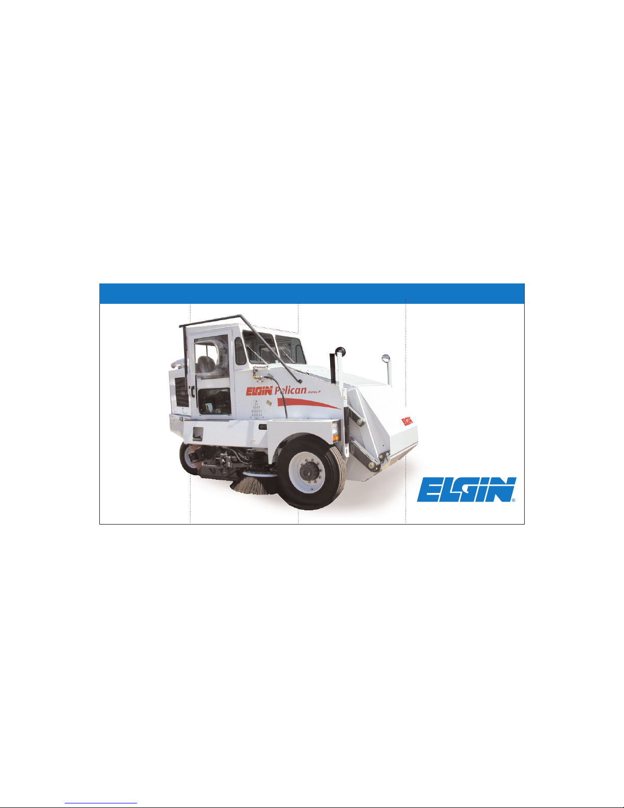
Pelican® P
OPERATORS MANUAL
Page 2

Page 3

PELICAN®SERIES P
OPERATORS MANUAL
Sweeper Serial Number_____________________________
Elgin Sweeper Company
Subsidiary of Federal Signal Corporation
1300 W. Bartlett Rd.
Elgin, IL 6012-
847-741-5370
P/N 0701450-E
Page 4

Printed in U.S.A. Copyright 2007 Elgin Sweeper Company
Page 5

Welcome to the World’s Most Popular
Three-Wheel Broom Sweeper -
The Elgin Pelican®Series P
i
Read this manual carefully and completely before operating the sweeper. Working with unfamiliar equipment
can lead to accidents. Understand and follow all safety
information when operating the sweeper.
Elgin employees carefully inspected the sweeper before
it left the factory. Your Elgin equipment dealer inspected the sweeper and made certain that it was in proper
working order prior to delivery.
To keep the Pelican sweeper in good working condition,
it is important to follow all maintenance and service
schedules, including
DAILY SERVICE - After every shift or 10 hours
PERIODIC SERVICE - After each period of 50, 150,
500 or 1000 hours
Refer to the maintenance schedule in the Maintenance
Section. This schedule is also displayed on the sweeper.
Keep this manual in the cab of the sweeper for reference. If a problem develops with the sweeper, your
Elgin Dealer has the factory-trained service personnel,
genuine Elgin parts and necessary tools and equipment
to meet your specific needs.
If you should need to contact the factory regarding
operation, maintenance or repair, please feel free to call
Elgin at 847-741-5370.
This manual will assist in the proper operation and care of the Elgin Pelican Series P Sweeper. It contains specific
information on features and specifications, suggested operating techniques, preventive maintenance hints and
instructions for making repairs and adjustments.
Page 6

ii
Page 7

LIMITED WARRANTY
Each machine manufactured by ELGIN SWEEPER COMPANY (“ESCO” or the
“Company”) is warranted against defects in material and workmanship for a
period of 12 months provided the machine is used in a normal and reasonable
manner. This limited warranty is applicable only to the original user-purchaser
for a period of twelve (12) months (as measured from the date of delivery to the
original user-purchaser) and is not transferable.
During the Limited Warranty Period ESCO will cause to be repaired or replaced, as the Company may elect, any part or parts
of such machine that the Company’s examination discloses to be defective in material or workmanship. Repairs or replacements
are to be made at the selling Elgin distributor’s location or at other locations approved by ESCO.
The ESCO Limited Warranty shall not apply to:
1. Major components or trade accessories such as, but not limited to, trucks, engines, hydraulic pumps and motors, tires and
batteries that have a separate warranty by the original manufacturer.
2. Normal adjustments and maintenance services.
3. Normal wear parts such as, but not limited to, brooms, oils, fluids, filters, broom wire, shoe runners, rubber deflectors and
suction hoses.
4. Failures resulting from the machine being operated in a manner or for a purpose not recommended by ESCO.
5. Repairs, modifications or alterations without the express written consent of ESCO, which, in the Company’s sole judgment,
have adversely affected the machine’s stability, operation or reliability as originally designed and manufactured.
6. Items subjected to misuse, negligence, accident or improper maintenance.
iii
R
Subsidiary of Federal Signal Corporation
Page 8

*NOTE* The use in the product of any part other than parts approved by ESCO may invalidate this warranty. ESCO reserves
the right to determine, in its sole discretion, if the use of non-approved parts operates to invalidate the warranty. Nothing contained in this warrant shall make ESCO liable for loss, injury or damage of any kind to any person or entity resulting from any
defect or failure in the machine.
TO THE EXTENT LIMITED BY LAW, THIS WARRANTY IS IN LIEU OF ALL OTHER WARRANTIES, EXPRESS OR
IMPLIED, INCLUDING WITHOUT LIMITATION, ANY IMPLIED WARRANTIES OF MERCHANTABILITY AND FITNESS
FOR A PARTICULAR PURPOSE.
This warranty is also in lieu of all other obligations or liabilities on the part of ESCO, including but not limited to, liability for
incidental and consequential damages on the part of the Company or the seller. ESCO makes no representation that the
machine has the capacity to perform any functions other than as contained in the Company’s written literature, catalogs or
specifications accompanying delivery of the machine. No person or affiliated company representative is authorized to alter the
terms of this warranty, to give any other warranties or to assume any other liability on behalf of ESCO in connection with the
sale, servicing or repair of any machine manufactured by the Company.
ESCO reserves the right to make design changes or improvements in its products without imposing any obligation upon itself to
change or improve previously manufactured products.
ELGIN SWEEPER COMPANY, 1300 West Bartlett Road, Elgin, Illinois 60120, U.S.A.
iv
Page 9

Safety
General ................................................................. S-1
Pelican P Safety Labels ....................................... S-9
Description
Elgin Pelican Series P Sweeper.......................... D-1
Principles of Operation
Why Sweep? .................................................. D-2
Mechanical/Broom Sweepers........................ D-2
Pelican ........................................................... D-2
Water Spray................................................... D-2
Brooms........................................................... D-3
Conveyor ........................................................ D-3
Hopper ........................................................... D-4
Cab ................................................................. D-4
Controls ......................................................... D-5
Drive Wheels ................................................. D-5
Guide Wheel .................................................. D-6
General Data ....................................................... D-7
Pelican P Side View............................................. D-9
Pelican P Front View......................................... D-10
Pelican P Rear View.......................................... D-10
Operation
Instruments and Controls................................... O-1
Operating Checklist ............................................ O-6
Starting the Engine............................................. O-8
Cold Weather Starting .........................................O-9
Transport............................................................ O-10
Sweeping ............................................................ O-12
Sweeping Patterns............................................. O-16
Reversing the Conveyor .................................... O-18
Dumping the Hopper......................................... O-19
Shutting Down the Unit ................................... O-21
At End of Shift....................................................O-21
Maintenance
Scheduled Maintenance.......................................M-1
Daily Service Checklist ................................ M-1
Periodic Service Checklist.............................M-2
After 50 Hours ....................................... M-2
After 150 Hours ..................................... M-2
After 500 Hours ..................................... M-3
After 1000 Hours ................................... M-3
Daily Washdown ................................................. M-7
v
Table of Contents
Page 10

Bubble Window Maintenance ............................ M-9
Lubrication .........................................................M-10
Service Procedures
Towing ...............................................................SP-1
Air Cleaner......................................................... SP-3
Fuel System ....................................................... SP-5
Draining Fuel Water Separator ................. SP-5
Changing Fuel Filter .................................. SP-7
Bleeding Fuel System ................................. SP-8
Hydraulic System .............................................. SP-8
Spray Water System.......................................... SP-9
Broom Adjustment........................................... SP-10
Side Broom Adjustment .............................SP-11
Side-To-Side Angle .............................. SP-11
Front-To-Back Angle........................... SP-11
Down Pressure.................................... SP-12
Main Broom Adjustment ...........................SP-13
Standard (Chain) Suspension............ SP-13
Hydraulic Suspension ........................ SP-13
Dirt Shoe Adjustment...................................... SP-14
Dirt Deflectors ................................................. SP-15
Conveyor........................................................... SP-16
Conveyor Access .........................................SP-16
Adjusting Conveyor................................... SP-18
Conveyor Belt Adjustments ................SP-18
Other Conveyor Adjustments..............SP-22
Replacing Conveyor Belt............................SP-25
Removing Conveyor Belt ...................SP-025
Squaring Conveyor Structure .............SP-26
Structure Stop Bolt Adjustment .........SP-27
Lower Roll Offset Adjustment.............SP-27
Installing Conveyor Belt .....................SP-28
Splicing Conveyor Belt...............................SP-29
Reversing Conveyor ...................................SP-30
Main Broom Replacement................................SP-32
Cab Air Filter ................................................... SP-34
Wheels And Tires............................................. SP-34
Winter Storage................................................. SP-34
Spring Startup ................................................. SP-36
Troubleshooting .......................................................T-1
Glossary .....................................................................G-1
vi
Page 11

RECOGNIZE SAFETY
INFORMATION
This is the safety-alert symbol. When you
see this symbol on your machine or in this
manual, be alert to the potential for personal
injury.
Follow recommended precautions and safe
operating practices.
UNDERSTAND SIGNAL WORDS
A signal word – DANGER, WARNING, or
CAUTION – is used with the safety-alert symbol. DANGER identifies the most serious hazards.
This symbol and these signal words appear on
the machine and in the operator’s manual.
Read and understand the following definitions
of the signal words before operating or working on the machine.
DANGER
DANGER is used to
indicate the presence of a hazard which will
cause severe personal injury, death, if the
warning is ignored.
WARNING
WARNING is used to
indicate the presence of a hazard which can
cause severe personal injury or death, if the
warning is ignored.
CAUTION
CAUTION is used to
indicate the presence of a hazard which will or
can cause minor personal injury, if the warning is ignored.
NOTICE
NOTICE indicates installation, operation, or maintenance information
which is important but not hazard-related.
!
SAFETY
S-1
SAFETY INFORMATION
!
!
!
Page 12
CALIFORNIA PROPOSITION 65
WARNING
Please note this warning and remember:
• Always start and operate the engine in a
well-ventilated area;
• If in an enclosed area, vent the exhaust to
the outside;
• Do not modify or tamper with the exhaust
system.
FOLLOW SAFETY
INSTRUCTIONS
Carefully read all safety messages in this
manual and on your machine safety signs.
Keep safety signs in good
condition. Replace missing or
damaged safety signs. Be sure
new equipment components
and repair parts include the
current safety signs.
Replacement safety signs are
available from your Elgin
Sweeper dealer.
Learn how to operate the machine and how to
use controls properly. Do not let anyone operate the machine without instruction.
Keep your machine in proper working condition. Unauthorized modifications to the
machine may impair function and/or safety
and affect machine life.
If you do not understand any part of this manual and need assistance, contact your Elgin
Sweeper dealer.
SAFETY
S-2
CALIFORNIA
PROPOSITION 65 WARNING
Diesel engine exhaust and some of its constituents
are known to the State of California to cause
cancer, birth defects and other reproductive harm.
Page 13

WEAR APPROPRIATE
CLOTHING/PROTECTION
Wear close fitting clothing and safety equipment appropriate to the job. Exercise caution
with anything that could be caught in the
machinery, such as jewelry and long hair.
Operating equipment safely requires the full
attention of the operator. Do not wear radio or
music headphones while operating the
machine. Use caution while using a cellular
telephone while operating the equipment.
Always wear appropriate protection to meet
any applicable industry standard or regulations.
DRIVING THE SWEEPER
Operate the sweeper only when all guards are
fitted and in their correct position.
Before moving the machine, check the immediate vicinity of the machine for bystanders. Use
the horn as a warning immediately before
moving the machine.
For speeds over 25 mph (40 km/h), the sweeper
must be operated from the primary driving
position (left-hand or right-hand) that is standard in the country where you are driving.
Operating at these speeds from the other driving position can result in severe injury or
property damage. While the driver is changing
driving position, the sweeper must be stopped
with the gearshift in neutral and the parking
brake applied.
HANDLE FUEL SAFELY —
AVOID FIRES
Handle fuel with care. It is highly
flammable. Do not refuel the
machine while smoking or when
near open flame or sparks.
SAFETY
S-3
Page 14

Always stop the engines before refueling the
machine. Fill the fuel tank outdoors.
Prevent fires by keeping the machine clean of
trash, grease, and debris. Always clean up
spilled fuel.
AVOID CONTACT WITH
MOVING PARTS
Everyone must be clear of the
sweeper before the engine is started and before the brooms are
started.
Many moving parts, such as the
side brooms, cannot be completely
shielded, due to their function.
Stay clear of these moving elements during operation.
Keep hands, feet, and clothing away from
power driven parts.
AVOID MACHINE INSTABILITY
Parking brake must be set before raising or
tilting the hopper.
If applicable, make sure the hopper door is
open before the hopper is raised or tilted.
Raise or tilt the hopper only when the sweeper
is parked on firm, level surfaces.
Lower the hopper to transport position before
moving the machine.
PARK SWEEPER SAFELY
Set the parking brake, turn off the engine,
and remove the keys.
Be sure the hopper is down before leaving
the sweeper.
SAFETY
S-4
Page 15

AVOID OVERLOADS
Observe the maximum permissible
axle loads and total weights.
AVOID ELECTRICAL POWER
LINES
Do not raise the hopper while under
power lines.
Do not raise the hopper while under
trees, bridges, etc.
Lower the hopper to transport position before
moving the machine.
PRACTICE SAFE
MAINTENANCE/REPAIRS
Keep the area clean and dry. Remove any
build-up of grease, oil, or debris.
Never lubricate or service the machine while it
is moving. Keep all parts in good condition and
properly installed. Fix damage immediately.
Replace worn or broken parts.
Make sure all maintenance and repairs are
completed by qualified and authorized personnel. All applicable industry standards and
practices and regulations must be followed
during maintenance and repairs.
Make sure the parking brake is set, before you
do any work on the sweeper.
SAFETY
S-5
Page 16
PREVENT BATTERY
EXPLOSIONS
Battery gas can explode. Keep
sparks and flames away from
batteries. If battery electrolyte
level must be checked, use an
electric light.
Never check battery charge by placing a metal
object across the posts. Use a voltmeter or
hydrometer.
Always remove the grounded (–) battery cable
first and connect it last.
Do not charge a frozen battery; it may explode.
Warm the battery to 60° F (16 °C).
AVOID OVERLOADING
ELECTRICAL SYSTEM
Before modifying, adding, removing,
etc. any electrical/electronic component(s), verify that the circuitry and
components do not overload the electrical system.
Contact your Elgin Sweeper dealer, if you have
any questions or need assistance.
SAFETY
S-6
Page 17
AVOID HIGH PRESSURE
FLUIDS
Escaping fluid under
pressure can penetrate
the skin, causing serious injury. Avoid the
hazard by relieving
pressure before disconnecting hydraulic or
other high pressure
lines. Tighten all connections before applying
pressure. Search for leaks with a piece of cardboard. Protect hands and body from high pressure fluids. If accident occurs, seek immediate
medical attention.
Keep hands and body away from pinholes and
nozzles which eject fluids under high pressure.
USE PROPER TOOLS
Use tools appropriate
to the work. Makeshift tools and procedures can create safety hazards.
Use power tools only to loosen threaded parts
and fasteners.
For loosening and tightening hardware, use
the correct size tools. DO NOT use U.S. measurement tools on metric fasteners, or vice
versa. Avoid bodily injury caused by slipping
wrenches.
Use only service parts meeting Elgin Sweeper
specifications.
SAFETY
S-7
Page 18

TIRES AND RIMS
An inflated tire and rim can be very dangerous
if improperly used, serviced or maintained. To
avoid serious injury, never attempt to reinflate a tire which has been run flat or seriously underinflated without first breaking
down the tire and wheel assembly for inspection. Do not attempt to add air to tires or
replace tires or wheels without first taking
precautions to protect persons and property.
For details see the regulations of the
Occupational Safety and Health
Administration (OSHA).
Never use a ring or other rim parts of different
manufacture or any different size or type than
original rims.
OBSERVE ENVIRONMENTAL
PROTECTION REGULATIONS
Be mindful of the environment and ecology.
Before draining any fluids,
find out the correct way to
dispose of them.
Observe the relevant environmental protection
regulations when disposing of oil, fuel, coolant,
brake fluid, filters, and batteries.
SAFETY
S-8
Page 19
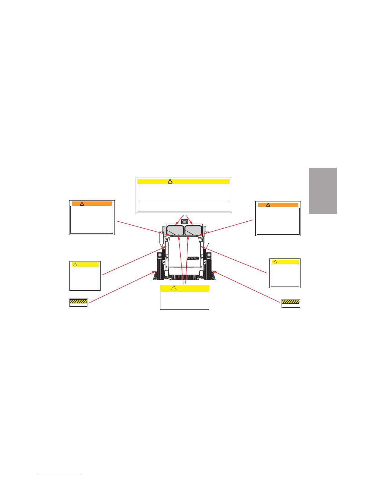
SAFETY
S-9
R
!
CAUTION
Towing with hubs
engaged will damage
hydrostatic drive.
Max. tow speed not to
exceed 20 MPH.
Set park brake, Remove
2 bolts & reverse cap
for disengagement at both
hubs. Release park brake
before towing vehicle.
No Step
PELICAN P SAFETY LABELS - PART ONE
The operator may not be able to see
directly in front of machine, and operating
with people in front of sweeper can cause
severe injury or death.
Ensure that area in front of machine is clear
before and while moving forward. Properly
adjust front 6" round convex mirrors before
operating and monitor them for people
outside of your direct field of vision.
Refer to Elgin Sweeper Tech Tip #0713074
WARNING
!
The operator may not be able to see
directly in front of machine, and operating
with people in front of sweeper can cause
severe injury or death.
Ensure that area in front of machine is clear
before and while moving forward. Properly
adjust front 6" round convex mirrors before
operating and monitor them for people
outside of your direct field of vision.
Refer to Elgin Sweeper Tech Tip #0713074
WARNING
!
!
CAUTION
Towing with hubs
engaged will damage
hydrostatic drive.
Max. tow speed not to
exceed 20 MPH.
Set park brake, Remove
2 bolts & reverse cap
for disengagement at both
hubs. Release park brake
before towing vehicle.
No Step
CAUTION
!
Before operating this machine,
read the operator’s manual
and operator’s instructions on the
sun visor.
!
CAUTION
Turning both steering wheels
at the same time will damage
the steering system.
Use only one wheel to steer at
any time.
Exceeding 2500 + 50 RPM
can damage the hydrostatic
drive system.
Do not exceed the
recommended 2500 RPM
engine speed.
Overloading the hopper can
cause personal injury or
damage to the sweeper.
To avoid possible injury or
property damage, read the
operator's manual before
using this machine.
Refer to maintenance chart
for daily and scheduled
servicing.
Maintenance and repairs
must be done by authorized
personnel only.
Dump hopper frequently when
loading heavy materials.
(At sun
visors)
(Inside
the cab)
(Inside
the cab)
(Inside
the cab)
Page 20
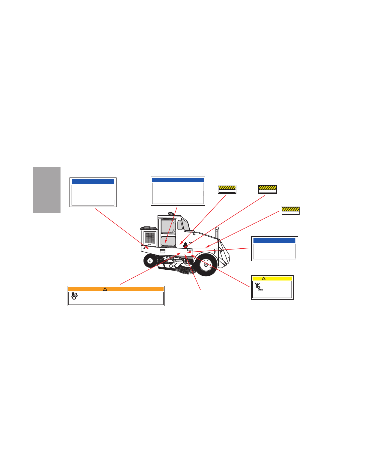
SAFETY
S-10
PELICAN P SAFETY LABELS - PART TWO
NOTICE
Tire Inflation Data
Front:
10:00-20 Load Range F (Tube)
10:00-20 Load Range G (Tube)
11R22.5 Load Range G (Tubeless)
Rear:
8.25-15 Load Range F (Tube)
7.50-15 Load Range H (Tube)
9R17.5HC Load Range H (Tubeless)
Maximum Rim Pressure (Tube)
Maximum Rim Pressure (Tubeless)
Maintenance Chart
on inner surface of
RH cover
No Step
No Step
No Step
Rotating Broom.
Can cause personal
injury.
Do not step on side broom
while rotating or at rest.
CAUTION
!
NOTICE
Replace the guide wheel pivot pin
(1001729) when servicing the guide
wheel assembly as a result of impact
damage. (Examples of impact damage
might be, but not limited to: Bent rim,
tire damage, axle damage, etc.)
Contact Elgin dealer with any questions.
NOTICE
Replace the guide wheel pivot pin
(1001729) on a 5000 hr interval, or
every 5 years (whichever occurs first),
or when servicing the guide wheel as
a result of impact damage.
Moving Parts.
Contact can cause
severe injury.
To avoid possible injury or property damage,
read the operator's manual before using this machine.
Maintenance and repairs must be done by authorized
personnel only.
Do not attempt repairs or
go underneath machine
with engine(s) running.
Use extreme care when
making checks or
adjustments that require
the engine(s) to be running.
WARNING
!
(On base
of seat)
(Behind RH cover)
(On inner surface
of RH cover)
(On both sides of
dual sweeper only)
(On both sides
of sweeper)
(On both sides
of sweeper)
(On both sides of
dual sweeper only)
Page 21
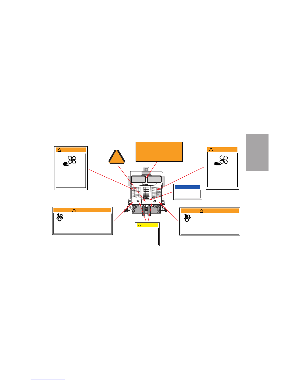
SAFETY
S-11
R
PELICAN P SAFETY LABELS - PART THREE
Moving Parts.
Contact can cause
severe injury.
To avoid possible injury or property damage,
read the operator's manual before using this machine.
Maintenance and repairs must be done by authorized
personnel only.
Do not attempt repairs or
go underneath machine
with engine(s) running.
Use extreme care when
making checks or
adjustments that require
the engine(s) to be running.
WARNING
!
Moving Parts.
Contact can cause
severe injury.
To avoid possible injury or property damage,
read the operator's manual before using this machine.
Maintenance and repairs must be done by authorized
personnel only.
Do not attempt repairs or
go underneath machine
with engine(s) running.
Use extreme care when
making checks or
adjustments that require
the engine(s) to be running.
WARNING
!
!
CAUTION
Towing with hubs
engaged will damage
hydrostatic drive.
Max. tow speed not to
exceed 20 MPH.
Set park brake, Remove
2 bolts & reverse cap
for disengagement at both
hubs. Release park brake
before towing vehicle.
Rotating Fan.
Can cause severe injury.
Keep clear of fan at all
times. Disconnect battery
before servicing.
WARNING
!
Rotating Fan.
Can cause severe injury.
Keep clear of fan at all
times. Disconnect battery
before servicing.
WARNING
!
WARNING
THIS VEHICLE IS EQUPPED WITH A
BACKUP ALARM
ALARM MUST SOUND WHEN BACKING
IT IS THE DRIVER'S RESPONSIBILITY
TO OPERATE THIS VEHICLE SAFELY
BE SURE BACKUP ALARM IS OPERATING
NOTICE
Lubricate sprung guide wheel
strut daily with lithium base
grease #2.
Slow Moving
Vehicle
(Inside
cab)
(At radiator)
(At radiator)
Page 22

SAFETY
S-12
Page 23
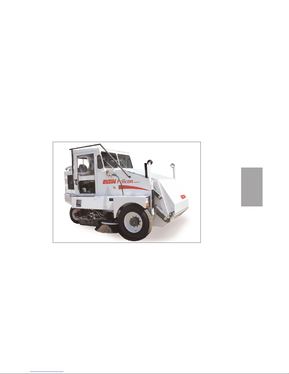
ELGIN
PELICAN
®
Series P
Sweeper
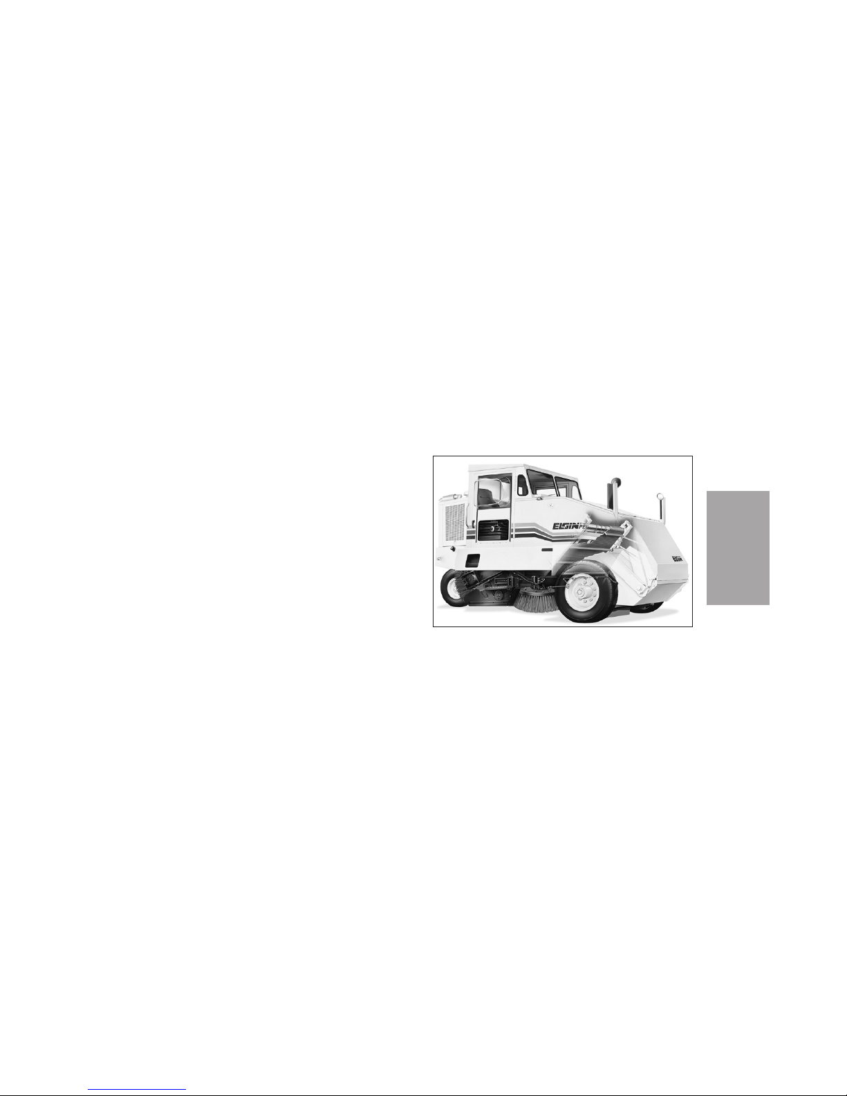
efficiently cleans
large, paved
areas, such as
streets and parking lots. It can be
equipped with a
broom on each side
to increase total
sweeping path.
Side brooms also
help to bring
debris out of the
gutter and onto
the conveyor.
D-1
DESCRIPTION
DESCRIPTION
Page 24

WHY SWEEP?
Street sweeping is an essential part of sanitation.
In health, ecology and aesthetics, the community
benefits from clean streets. Clean streets reduce
dust and dust-borne contaminants, bacteria from
decomposition of organic matter, pollutants entering stormwater systems and accidents due to debris
in the roadway. Community pride is enhanced by a
clean environment. People are less likely to litter in
a clean area. Tourists have a positive first impression of the community, which may encourage them
to stay longer and return more often.
MECHANICAL/BROOM SWEEPERS
Mechanical, or broom, sweepers remove debris by
sweeping it onto a conveyor. The conveyor carries
the debris to a hopper. The No-Jam™ hopper conveyor of Elgin Pelican was originally patented. This
revolutionary design sweeps debris up onto the conveyor, eliminating the problems of jamming.
PELICAN
The Pelican is the world’s most popular sweeper.
This three-wheel design is flexible enough to get
into tight corners and around parked cars, yet
capable of picking up large objects, such as branches, hub caps and bottles. When the hopper is full,
the Pelican hopper dumps straight ahead into a
dump truck or onto the ground. This straight ahead
approach uses only one lane, to avoid blocking traffic.
WATER SPRAY
A water spray system controls dust during sweeping. Nozzles spray water at the front edge of each
side broom to moisten the dust being swept by the
brooms.
DESCRIPTION
D-2
PRINCIPLES OF OPERATION
Page 25
The amount of water is adjustable through use of a
knob inside the cab. A 180-gallon (681 L) water
tank is standard on the Pelican P, with an optional
40-gallon (151 L) tank available.
BROOMS
Hydraulically-driven brooms sweep the debris on
the street onto the conveyor. The main broom is
located behind the lower edge of the conveyor and
directs the debris toward the conveyor. Side brooms
are available on both the right and left sides. For
sweeping these are lowered and rotated to move
gutter debris to the conveyor.
The pattern that the brooms produce when the
sweeper is stationary is a tool to evaluate the most
efficient positioning of the brooms. The brooms can
be adjusted to produce the best pattern and result.
CONVEYOR
The heavy-duty, multi-ply reinforced No Jam™
debris conveyor (Figure D-1) transports debris
D-3
DESCRIPTION
Pelican P conveyor system
Figure D-1
Page 26
deposited on it by the main broom to the hopper.
Speed is in-cab controlled for variable forward and
reverse.
Pavement contact is maintained by rubber dirt
shoes on the sides and rubber deflectors under the
chassis.
HOPPER
Debris is collected in the 3.5 yd3(2.7 m3) volumetric capacity hopper. The forward dumping hopper
allows dumping to occur using only one lane of traffic. The dumping height is variable up to 9 ft 6 in.
(2895 mm).
After dumping the hopper should be washed down
for maximum efficiency and long life.
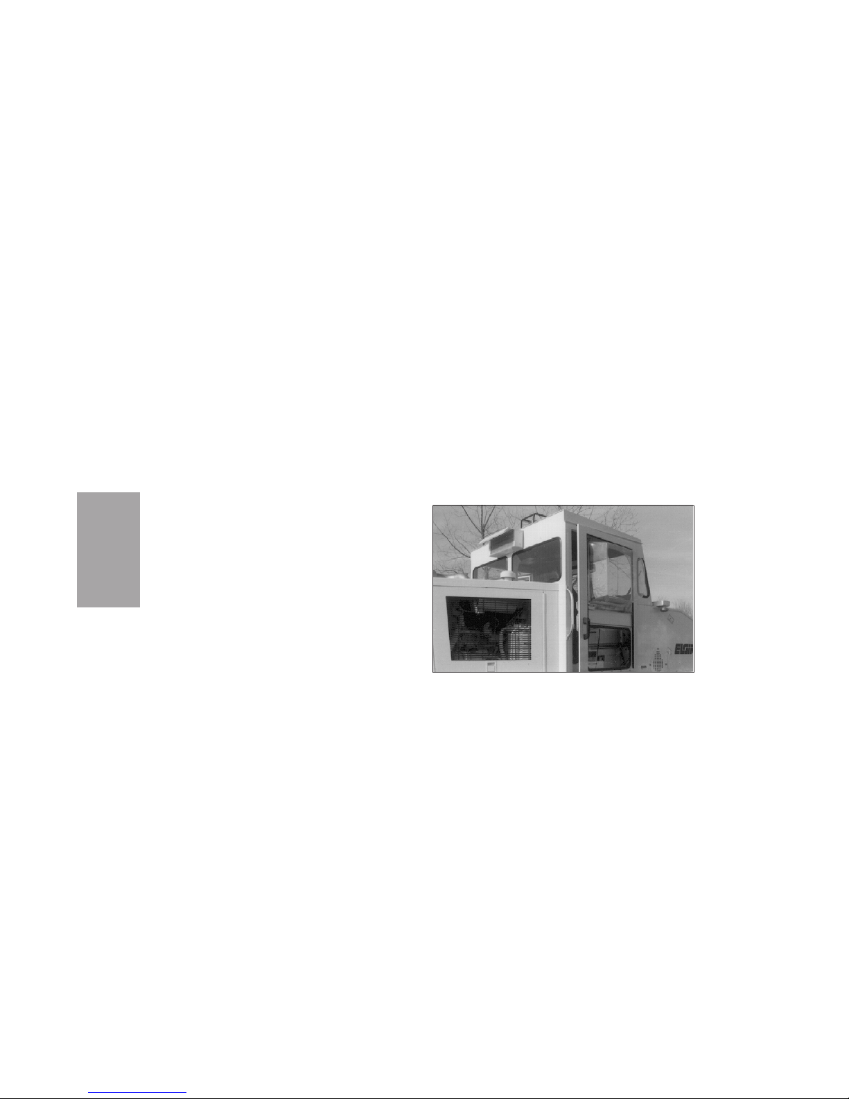
CAB
Visibility is a full 360° in the cab of the Pelican P
(Figure D-2). The bubble windows on each door, a
full-width windshield and rear windows allow the
operator to see everything that is happening while
sweeping.
DESCRIPTION
D-4
360° Visibility
Figure D-2
Page 27
CONTROLS
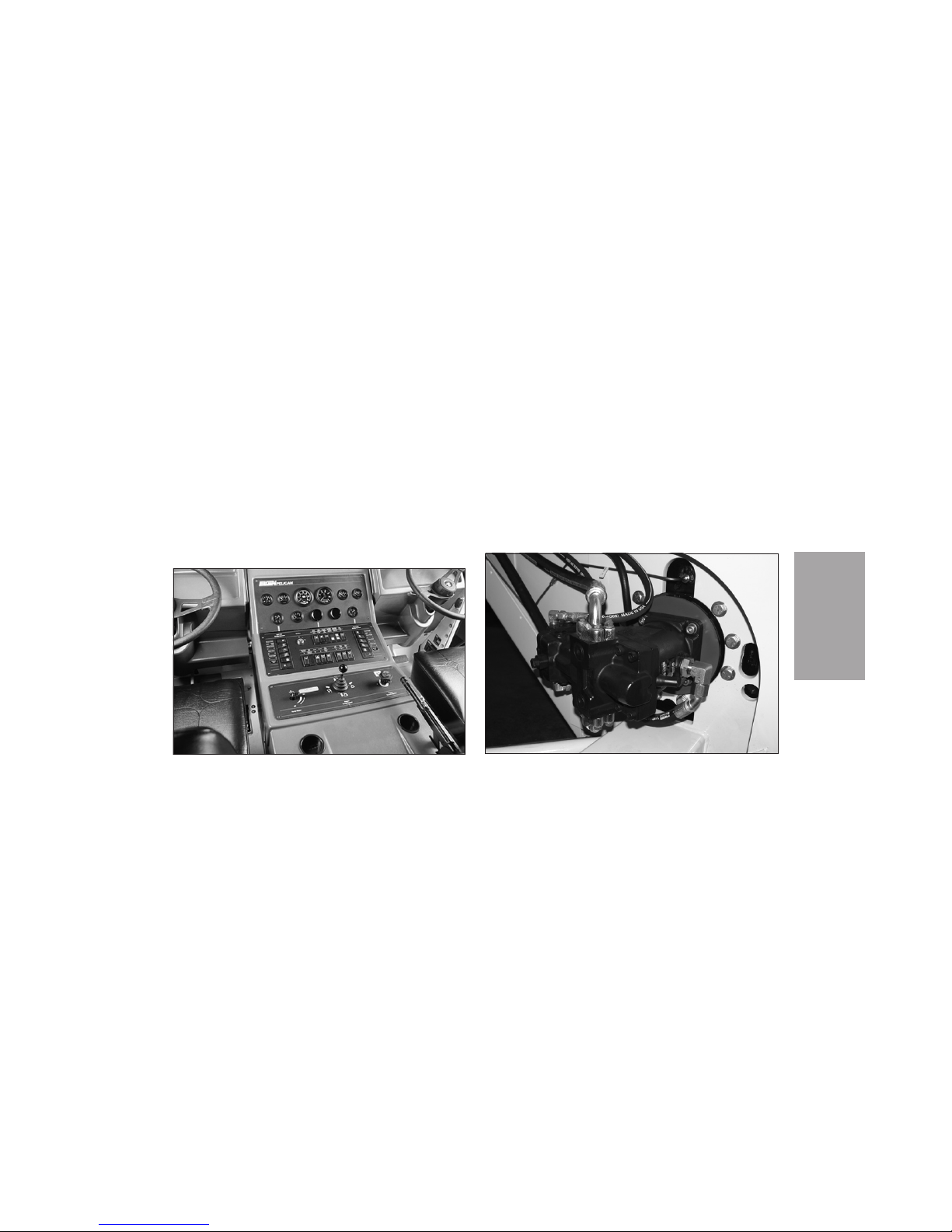
All sweeping functions, including brooms and hopper, are powered through in-cab controls (Figure D-
3), located comfortably within reach.
For a complete description of all controls, see the
Operations Section.
DRIVE WHEELS
The Pelican P features a unique wheel motor
design (Figure D-4) to provide power to handle all
road conditions include steep grades. Sensors
adjust the power required according to the load.
D-5
DESCRIPTION
Pelican P in-cab controls
Figure D-3
Drive Wheel Motor
Figure D-4
Page 28
GUIDE WHEEL
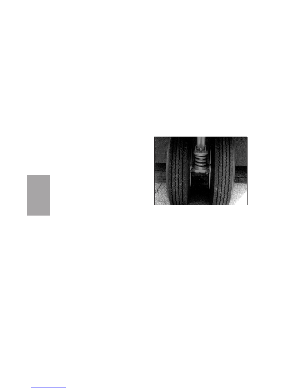
The rear, dual-tire, guide wheel (Figure D-5) allows
superior maneuverability to get around parked cars
and tight corners.
An optional sprung guide wheel increases operator
comfort and decreases stress on the sweeper. The 4spring suspension absorbs shock and is especially
important in areas with a number of potholes.
DESCRIPTION
D-6
Optional Sprung Guide Wheel
Figure D-5
Page 29

General Specifications
Wheel base .......................127.4 in (3236 mm)
Overall length ..............15 ft 10 in (4826 mm)
Overall height ..................9 ft 7 in (2921 mm)
Overall width ...................8 ft 6 in (2591 mm)
Turning radius (sweeping)....15 ft (4572 mm)
Brooms
Side broom diameter ..............36 in (914 mm)
Main broom diameter.............35 in (889 mm)
Main broom length ...............66 in (1676 mm)
Hydraulic system
Pump ...........................Variable displacement
Motor............................Variable displacement
Filter, return....................10 micron, full-flow
with bypass
Reservoir capacity.....................28 gal (106 L)
Refill capacity.........................35 gal (132.5 L)
Conveyor
Type ........Multiple ply reinforced rubber belt
Speed ....................Variable with engine RPM
Fuel tank capacity
Standard.................................35 gal (132.5 L)
Water system
Tank capacity..........................180 gal (681 L)
Filter .....................................100 mesh screen
Spray nozzles Atomizing, adjacent to
each broom
Fill hose length............16 ft 8 in (5.1 m) with
coupling
Washdown.................Integral cascade hopper
/conveyor wash
Pump ...............Centrifugal, 5 GPM (19 LPM)
at 40 PSI (2.8 bar)
D-7
DESCRIPTION
GENERAL DATA
Page 30

DESCRIPTION
D-8
Sweeping paths
One side broom........................8 ft (2438 mm)
Two side brooms................... 10 ft (3048 mm)
Debris Hopper
Maximum dump height............Up to 9 ft 6 in
(2895 mm)
Dumping clearance height....16 ft (4877 mm)
Design lift capacity ...........9,000 lb (4,080 kg)
Volumetric capacity.................3.5 yd
3
(2.7 m3)
Material volume .........................3 yd3(2.3 m3)
Engine
John Deere Diesel 4045TF150
Cylinders ........................................................4
Displacement ............................276 in
3
(4.5 L)
Horsepower.......99 HP (74 kW) at 2500 RPM
Torque .........274 lb-ft (372 Nm) at 1400 RPM
Compression Ratio ....................................17:1
Bore .................................4.19 in (106.43 mm)
Stroke .....................................5.0 in (127 mm)
Electrical system
Alternator...........................105 amp standard
Battery.................12 volt, group 31, 925 CCA
Tires
Front ...................................11R22.5 14 ply (2)
Rear ......................................9R17.5 16 ply (2)
Page 31
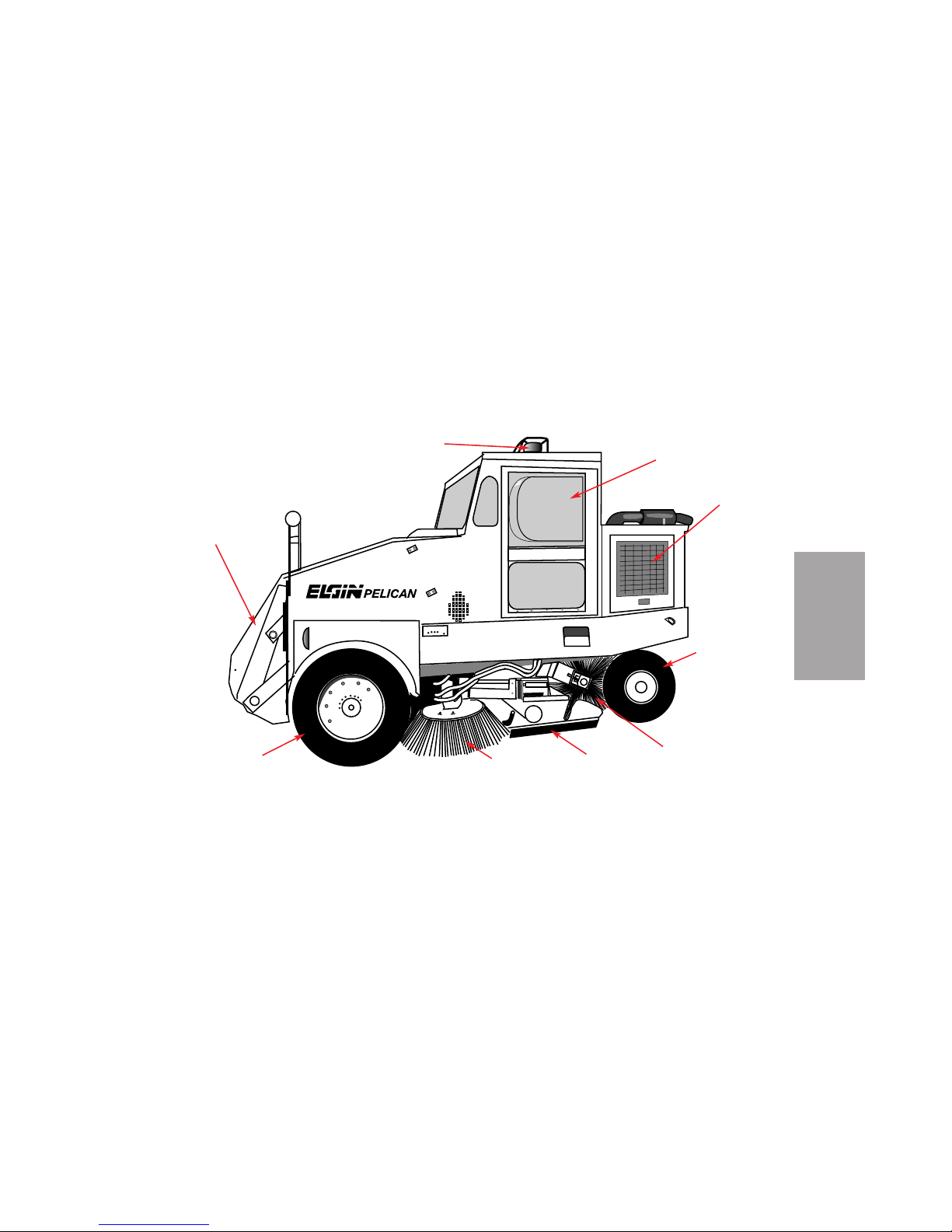
D-9
DESCRIPTION
Series P
Main Broom
Side Broom
Dirt Shoe
Hopper
Guide
Wheel
Drive Wheel
Bubble Window
Beacon
Engine
Compartment
Pelican P Side View
Figure D-6
Page 32
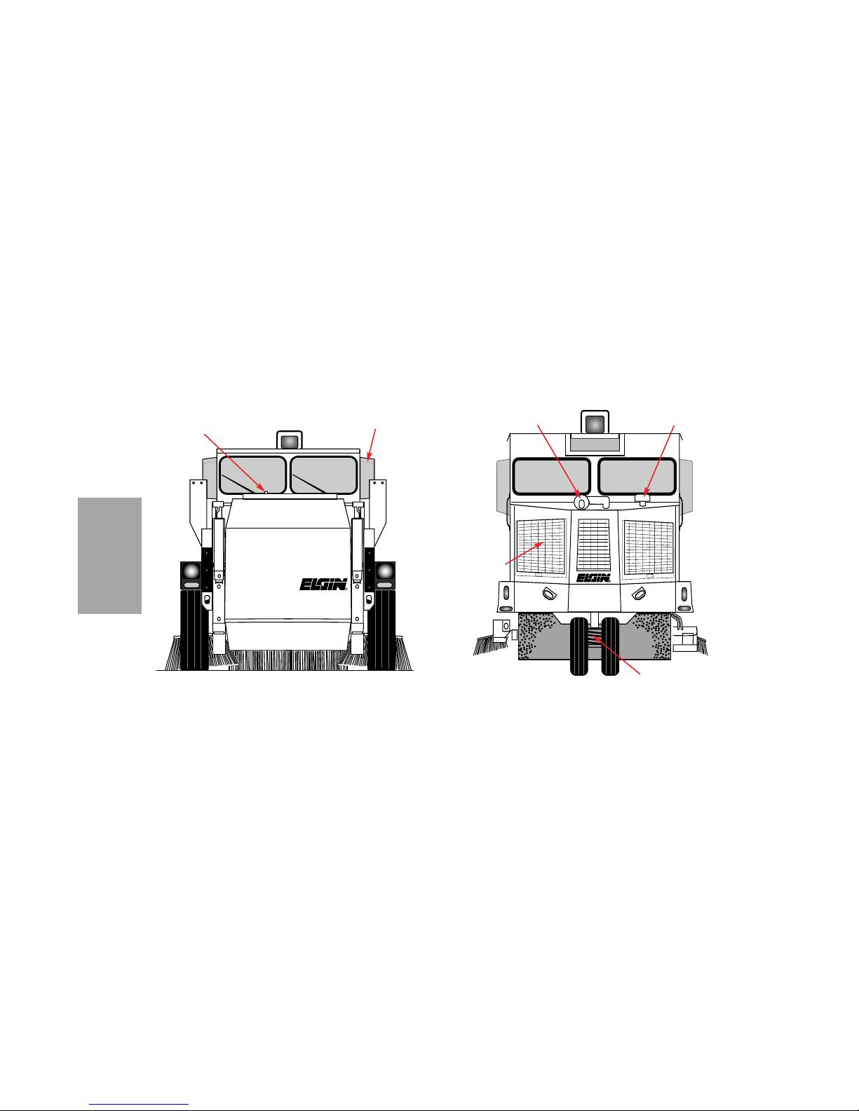
DESCRIPTION
D-10
R
R
Pelican P Front View
Figure D-7
Pelican P Rear View
Figure D-8
Spray
Water
Gauge
Bubble
Window
Engine
Compartment
Exhaust
Air
Precleaner
Sprung
Guide Wheel
Page 33

Before operating the Elgin Pelican P, be certain that
you have read and understand all safety and operation information. If you have any questions, contact
your supervisor before proceeding.
INSTRUMENTS & CONTROLS
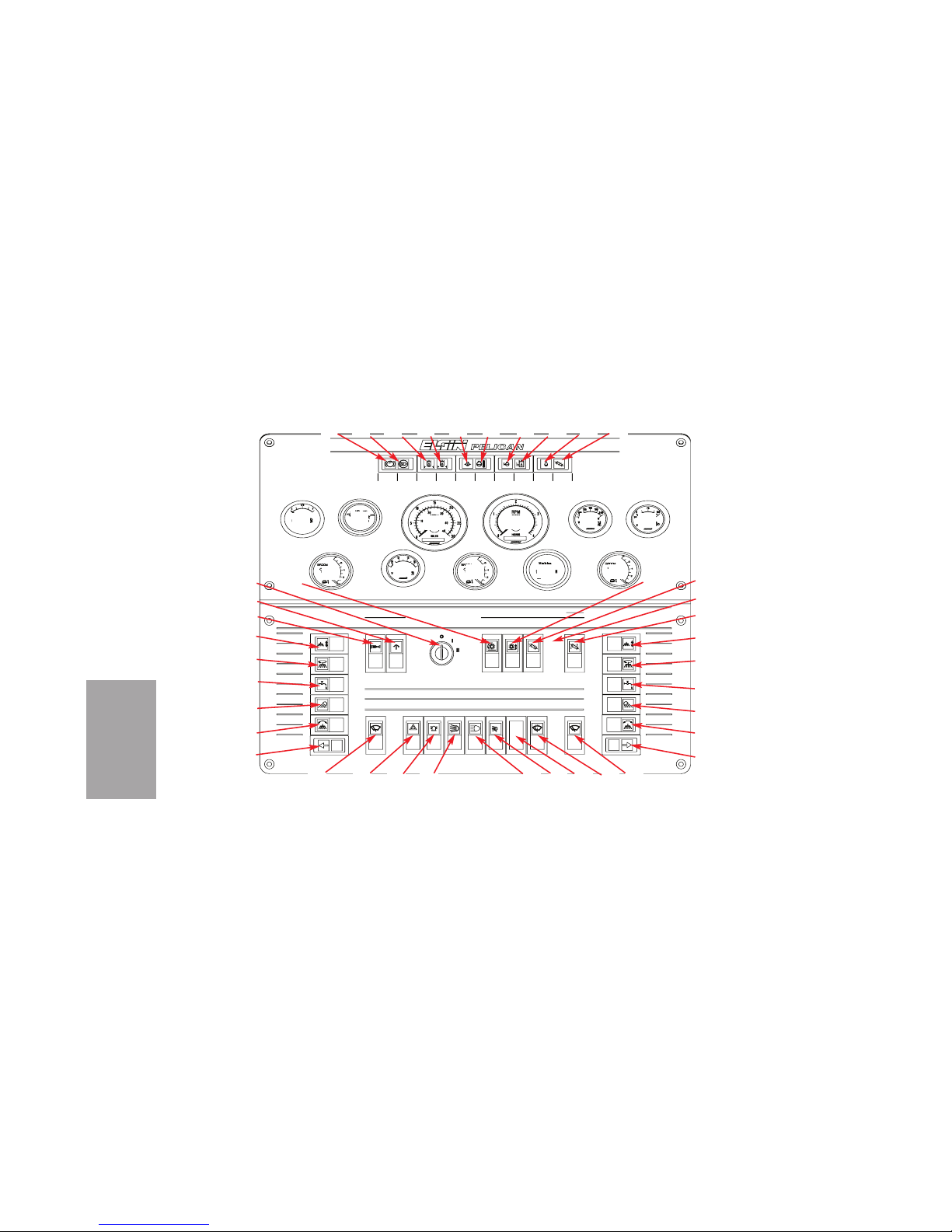
The numbers below refer to those indicated on
Figures O-1 and O-2.
1. Parking Brake On indicator - Indicates that
the parking brake is applied.
2. Restricted Air Filter indicator - Indicates
that the engine air filter is clogged and in need of
service.
3. Restricted Hyd. Filter indicator - Indicates
that one of the return filters at the hydraulic fluid
reservoir is clogged and in need of service.
4. Restricted Drive Filter indicator - Indicates
that the hydraulic fluid filter for the hydrostatic
drive is clogged and in need of service.
5. Low Eng. Oil Press. indicator (optional) -
Indicates that the pressure of lubricating oil in the
engine is too low for safe operation.
6. High Coolant Temp. indicator (optional) Indicates that the temperature of the engine
coolant is too high for safe operation.
7. Low Coolant Level indicator (optional) -
Indicates that the level of engine coolant is too low
for safe operation.
8. Low Hydraulic Oil Level indicator (optional)
- Indicates that the level of fluid in the hydraulic
system is too low for efficient operation.
9. Low/No Spray Water indicator (optional) -
Indicates that the supply in the water tank has
been nearly or completely used up.
O-1
OPERATION
OPERATION
Page 34
OPERATION
O-2
Spray
Water
Coolant
Temp.
Off/Rev
Raise
Up
On
Lower
Off
High
Low
Oil Press
Air Filter
Beacon
Off
On
High
Low
Off
Off
Rev/Off
Raise
Up
Off
Off
Raise
Off
Conveyor
Coolant
Temp.
On
Lower
Spray Water
Broom Rotate
Broom Height
Down
On
Broom Tilt
Broom Light
Flood
Rear
On
Off
Height
MB/Conv
Rotate
Main Broom
Drive Filter
Brake ON
Battery
Override
Shut Down
Ignition
Head
Off
Park Lts.
Head Lts.
Lights
Override
Hold For
Lower
On
Spray Water
Broom Rotate
Broom Height
Broom Light
Broom Tilt
Down
On
High
Low
Low/no
Stalled
Parking
Restricted
Restricted
Low Eng.
RH Side Broom Position
Engine Oil Pressure
Hydraulic
Oil Level
Low
Broom Hours
Sweep Controls
Right Side
Washer
Windshield
Off
Forward
Reverse
Conveyor
Rotate
Restricted
Hyd Filter
Hold For Fluid
Fuel
Sweep Controls
Left Side
Hazard
HAZARD
On
Off
On
Off
On
Engine Coolant Temp.
Wiper
Right
Off
MB/CONV Up
CONV Lower
Raise
Lower
LH Side Broom Position
Hydraulic Oil Temp.
Wiper
Left
Fluid Injection
Release For
Hold For 2 sec.
(Ether)
Cold Start
Off
On
High
Beam
Main Broom Position
Control Console
Figure O-1
1 2
3
4
5
6
7
8
9
10
11
12
13
14
15
16
17
18
19
20
21
50
49
48
47
41
42
43
44
45
46
32
33
34
35
36
37
38
39
40
30
22
23
24
25
26
27
28
29
31
Page 35

10. Stalled Conveyor indicator (optional) -
Indicates that the conveyor belt is not moving when
power is applied to the conveyor motor.
11. Fuel gauge - Indicates the quantity of fuel
remaining in the fuel tank.
12. Hydraulic Oil Temp. gauge - Indicates the
temperature of hydraulic fluid in the reservoir.
13. MPH / MILES - Speedometer indicates sweep-
er speed, and the odometer records distance travelled.
14. RPM X 1000 / HOURS - Tachometer indicates
speed of the engine. After initial start-up idling, the
hour meter records engine running hours.
15. Engine Coolant Temp. gauge - Indicates the
temperature of coolant at the engine.
16. Engine Oil Pressure gauge - Indicates oil
pressure at the engine.
17. LH Side Broom Position gauge (optional) Indicates vertical position of the left side broom on
units equipped with a left side broom.
18. Battery gauge - Indicates battery voltage.
19. Main Broom Position gauge (optional) Indicates if the main broom is up or down.
20. Broom Hours meter (optional) - Records total
time the main broom has operated.
21. RH Side Broom Position gauge (optional) Indicates vertical position of the right side broom
on units equipped with a right side broom.
22. Main Brm Rotate switch - Indicates oil pressure at the engine.
23. Ignition key switch - Switches the electrical
system (position I) or the starter (position II) on or
off.
O-3
OPERATION
Page 36

24. Shut Down Override switch (optional) - The
automatic engine shutdown feature protects
against damage from high coolant temperature or
low oil pressure. In a sweeper with this feature,
depress this switch while starting the engine.
25. Cold Start (Ether) switch (optional) - Under
cold weather conditions, depressing this optional
switch while holding the Ignition switch in the
start (II) position will release ether to aid in starting. Note: A full ether bottle must be installed
before using this switch.
26. Left Side Broom Height switch (optional) -
Lowers or raises the optional left side broom.
27. Left Side Broom Rotate switch (optional) -
Switches the optional left side broom motor on or
off.
28. Left Side Spray Water switch (optional) -
Switches spray water on or off at the optional left
side broom.
29. Left Side Broom Light switch (optional) -
Switches the light on or off at the optional left side
broom.
30. Left Side Broom Tilt switch (optional) -
Adjusts the side-to-side angle of the optional left
side broom.
31. Left turn signal
32. Left Wiper switch - Switches the left-hand
windshield wiper on or off.
33. Hazard switch - Switches hazard lights on or
off.
34. Beacon switch (optional) - Switches optional
beacon on and off.
35. Head Lights switch - Three-position switch
that switches headlights and parking lights on or
off.
OPERATION
O-4
Page 37

36. High Beam switch - Switches the high beam of
the headlights on or off.
37. Rear Flood switch (optional) - Switches the
optional rear floodlight on or off.
38. Not used
39. Windshield Washer switch - Operates the
windshield washer.
40. Right Wiper switch - Switches the right-hand
windshield wiper on or off.
41. Right turn signal
42. Right Side Broom Tilt switch - Adjusts the
side-to-side angle of the right side broom.
43. Right Side Broom Light switch - Switches
the light on or off at the right side broom.
44. Right Side Spray Water switch - Switches
spray water on or off at the right side broom.
45. Right Side Broom Rotate switch - Switches
the right side broom motor on or off.
46. Right Side Broom Height switch - Lowers or
raises the right side broom.
47. CONV LOWER / MB/CONV UP switch
(optional) - Installed only on sweepers with
hydraulic main broom suspension, the switch lowers only the conveyor, but it raises the main broom
and conveyor together.
This switch is used to return the main broom and
conveyor to transport position.
48. Not used
49. Conveyor Rotate switch - Three-position
switch that starts or stops the conveyor and controls forward or reverse rotation.
50. MB / Conv Height switch- Lowers the main
broom and conveyor together.
On sweepers with standard main broom suspension, the switch also raises the main broom and
conveyor together.
O-5
OPERATION
Page 38
On sweepers with hydraulic main broom suspension, once the conveyor is fully lowered to sweep
position, the switch raises or lowers the main
broom with no effect on conveyor position.
This switch is used to begin sweeping, set the main
broom pattern, and adjust the pattern during
sweeping.
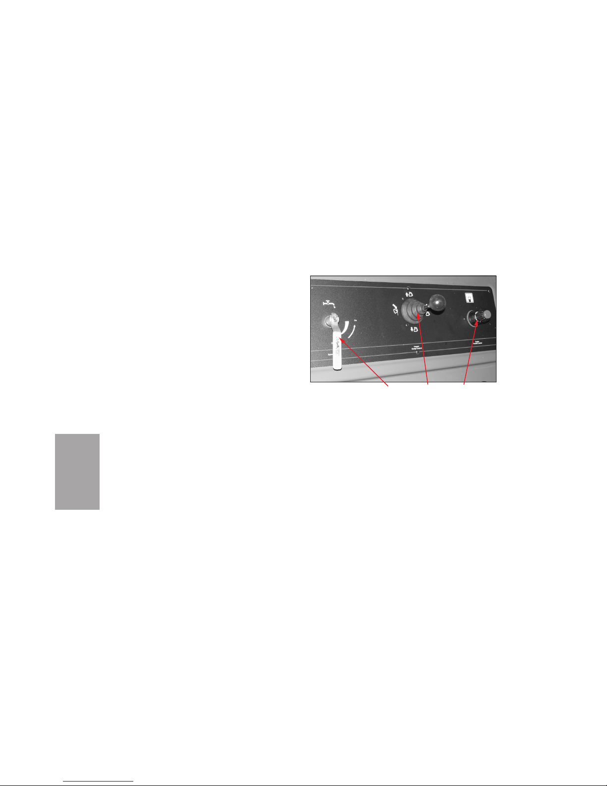
51. Spray Water valve - Allows the amount of
spray water to be regulated according to the sweeping conditions.
52. Hopper Dump Control - Lever controls the
motion of the hopper.
53. Engine Throttle Control - Knob controls
speed of the engine.
OPERATING CHECKLIST
Successful operation of the Pelican P depends on
the following standard daily procedures.
Before Starting Engine
ENGINE
• Check engine oil level.
• Check radiator coolant level.
OPERATION
O-6
Lowest Panel Of Control Console
Figure O-2
52
53
51
Page 39

• Check battery fluid level (if applicable).
NOTICE
Use #1 or #2 diesel fuel only.
• Check fuel tank. Fill, if necessary. Filling the
tank at the end of the shift will prevent condensation in the tank as moist air cools.
• Clean engine pre-cleaner (if applicable).
• Drain the water separator on the fuel filter.
• Check hydraulic oil reservoir level.
LIGHTS, MIRRORS, TIRES
• Check directional and safety lights.
• Check backup alarm.
• Check tires for correct pressure, according to tire
manufacturer.
• Check mirrors for visibility. As instructed at
Transport , make sure convex mirrors at front of
sweeper give full field of vision.
SPRAY WATER
•Check spray water filter.
• Fill water tank after flushing hydrant. Flush
hydrant before connecting to fill hose to remove
impurities in the water. Fill to overflowing. Close
hydrant slowly to prevent damage to hydrant.
SWEEPING COMPONENTS
• Check dirt shoes and dirt deflectors for wear and
for proper adjustment.
• Check main broom for wear.
• Check side brooms for wear.
• Check conveyor for wear and alignment.
After Starting Engine
• Check sweeping patterns of side broom(s) and
main broom.
• Operate water spray system and check for correct
spray pattern at side broom and main broom nozzles.
• If indicator shows restricted air flow to engine,
clean air cleaner and install new filter elements.
• Cycle and check all other sweeping functions.
O-7
OPERATION
Page 40

STARTING THE ENGINE
WARNING
Whenever possible, start and operate engine in
a well-ventilated area. If in an enclosed area,
vent the exhaust to the outside. DO NOT modify or tamper with the exhaust system.
NOTICE
If sweeper must be operated at temperatures below
freezing, see COLD WEATHER STARTING.
1. Make sure parking brake is engaged.
2. If the unit is equipped with the optional automatic shutdown feature to protect from damage due to high coolant temperature or low oil
pressure, depress the Shut Down Override
switch (24, Figure O-1) while starting the
engine.
NOTICE
Never operate the starter for more than 10 seconds.
Longer operation will lead to an over discharge of
the batteries, as well as starter seizure. Wait at least
30 seconds between attempts to start the engine.
3. Start the engine by turning the Ignition switch
(23) clockwise as far as it will go. Hold the
switch in that position until the engine begins
running, but no longer than 10 seconds. If the
engine fails to start within 10 seconds, wait at
least 30 seconds before trying again.
4. Allow the engine to warm up at normal idling
speed of 1000 rpm. To raise RPM, depress the
button on the Engine Throttle Control (53,
Figure O-2) to release the lock, and pull the
throttle knob up. For fine tuning, rotate the
control clockwise or counterclockwise.
!
OPERATION
O-8
Page 41

5. Check the Engine Oil Pressure and Fuel
gauges (16 and 11, Figure O-1) to be sure there
are no problems.
COLD WEATHER STARTING
WARNING
Whenever possible, start and operate engine in
a well-ventilated area. If in an enclosed area,
vent the exhaust to the outside. DO NOT modify or tamper with the exhaust system.
NOTICE
If operating the sweeper in temperatures below 32ºF
(0ºC), any water in the system will freeze.
Operation in temperatures below freezing may
require use of the optional cold weather starting
kit. If the sweeper is equipped with this feature,
proceed as follows:
1. Verify that a full ether bottle is installed.
2. Make sure the parking brake is engaged.
NOTICE
Never operate the starter for more than 10 seconds.
Longer operation will lead to an over discharge of
the batteries, as well as starter seizure. Wait at least
30 seconds between attempts to start the engine.
3. If unit is equipped with the optional automatic
shutdown feature to protect from damage due
to high coolant temperature or low oil pressure, depress the Shut Down Override switch
(24, Figure O-1) while starting the engine.
4. Hold the Ignition switch (23) in the starting
position until the engine starts, but no longer
than 10 seconds. While holding the Ignition
switch in the start (II) position, press the Cold
Start switch (25). If the engine fails to start
within 10 seconds, wait at least 30 seconds
before trying again.
5. If the engine is coughing, press the Cold Start
switch again. The switch will not be operational if the engine speed is more than 500
rpm.
!
O-9
OPERATION
Page 42

6. Allow the engine to warm up at normal idling
speed of 1000 rpm. To raise RPM, depress the
button on the Engine Throttle Control knob
(53, Figure O-2) to release the lock, and pull
the knob up. For fine tuning, rotate the knob
clockwise or counterclockwise.
7. Check the Engine Oil Pressure and Fuel
gauges (16 and 11, Figure O-1) to be sure there
are no problems.
TRANSPORT
WARNING
The operator may not be able to see directly in
front of machine, and operating with people in
front of sweeper can cause severe injury or
death.
Ensure that area in front of machine is clear
before and while moving forward. Properly
adjust front round convex mirrors before oper-
ating and monitor them for people outside of
your direct field of vision.
WARNING
With dual steering — Turning both steering
wheels at the same time will cause unpredictable steering. To prevent serious injury or
death, use only one steering wheel at a time to
steer the sweeper.
CAUTION
If the operator has not operated a vehicle with
rear-wheel steering, the operator must practice driving the Pelican in a non-congested,
open area until totally familiar with the steering.
CAUTION
With dual steering — While the driver is
changing driving position, the sweeper must
be stopped with the propel pedal in neutral
and the parking brake applied.
!
!
!
!
OPERATION
O-10
Page 43
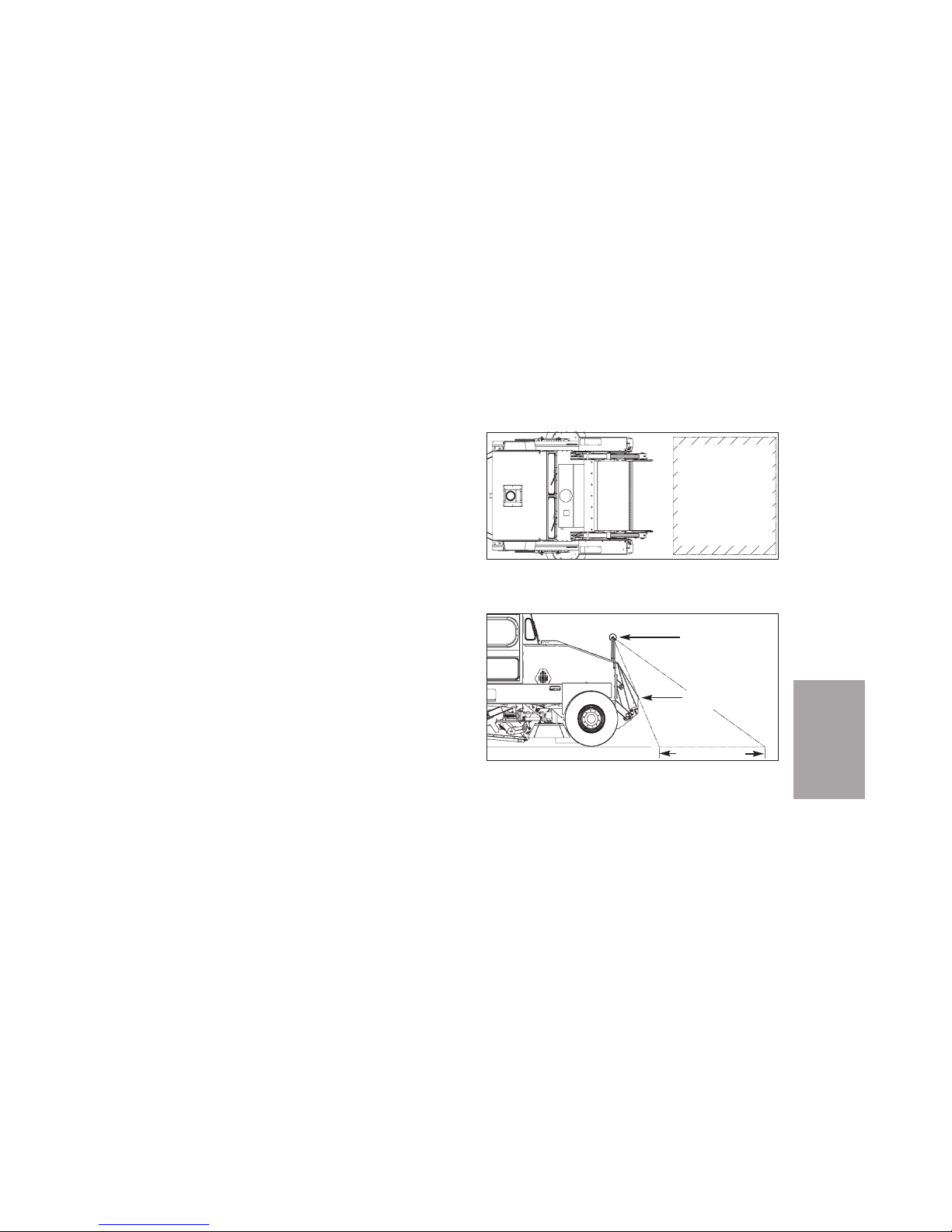
O-11
OPERATION
1. At the front of the sweeper, properly adjust the
round, convex mirrors (Figures O-3 and O-4)
to give an operator in either operating position
a clear view of any and all obstacles and/or
pedestrians in front of the sweeper.
2. After starting and warming up the engine,
turn on the needed lights by using the Hazard
(33, Figure O-1), Head Lights (35), and optional Beacon (34) switches.
3. Release the parking brake.
4. As necessary, stop rotation of the brooms and
conveyor by using the Broom Rotate switches
(22, 27, 45) and Conveyor Rotate switch (49).
5. As necessary, raise the side brooms to transport position by using the Broom Height
switches (26, 46).
6. If the sweeper has standard main broom suspension, use the MB / Conv Height switch (50)
to raise the main broom and conveyor.
If the sweeper has hydraulic main broom
Top View Of Sweeper
Figure O-3
Side View Of Sweeper
Figure O-4
Approximate field
of vision when
mirrors are
properly adjusted.
Field of vision
should include
entire top leading
edge of hopper as
a visual reference.
Field of vision
Top leading edge
of hopper
Convex mirror
Page 44
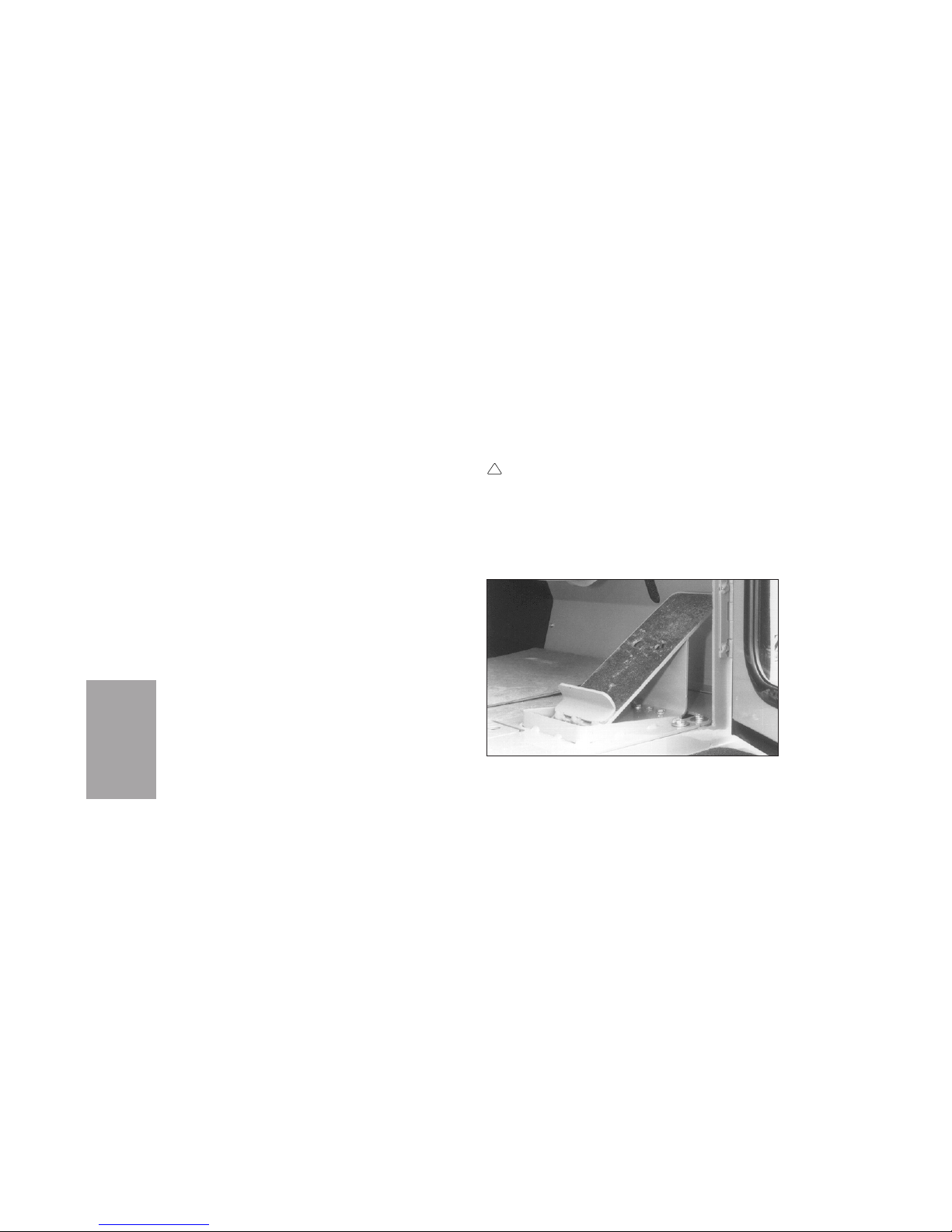
suspension, use the CONV LOWER /
MB/CONV UP switch (47) to raise the main
broom and conveyor.
7. Set the Engine Throttle Control (53, Figure
O-2) for transport RPM.
8. Turn on the lights, using the Hazard switch
(33), Head Lights switch (35), and optional
Beacon switch (34) as needed.
9. Ensure that the front of the machine is clear
before moving it forward. During operation of
the sweeper, monitor the front round mirrors
for people outside of your direct field of view.
10. To move the sweeper forward, press the upper
end of the propel pedal (Figure O-5). To move
the sweeper backward, press the lower end of
the pedal.
11. Releasing the propel pedal will result in
dynamic braking which will slow the sweeper.
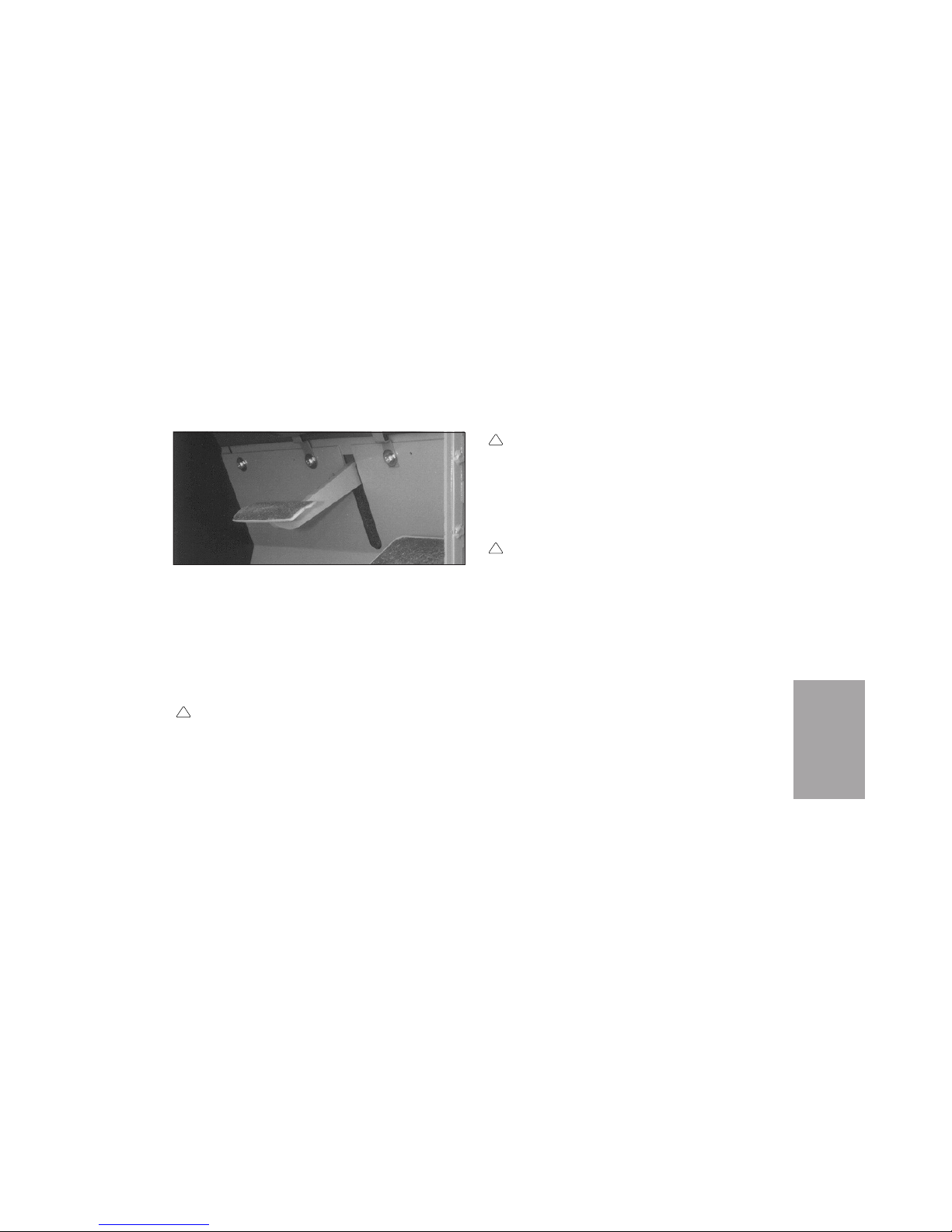
For additional braking, use the service brake
pedal (Figure O-6) located next to the propel
pedal.
SWEEPING
WARNING
The operator may not be able to see directly in
front of machine, and operating with people in
front of sweeper can cause severe injury or
death.
Ensure that area in front of machine is clear
!
OPERATION
O-12
Propel Pedal
Figure O-5
Page 45
O-13
OPERATION
CAUTION
If the operator has not operated a vehicle with
rear-wheel steering, the operator must practice driving the Pelican in a non-congested,
open area until totally familiar with the steering.
CAUTION
With dual steering — While the driver is
changing driving position, the sweeper must
be stopped with the propel pedal in neutral
and the parking brake applied.
1. Before operating the sweeper, adjust the front
round mirrors as instructed at Transport.
2. Before engaging sweeping components, bring
the Pelican to a complete stop and idle the
engine at 1000 rpm.
3. Lower the main broom and conveyor together
by using the MB/Conv Height switch (50,
Figure O-1). Press the switch until the
conveyor reaches its lowest position.
!
!
before and while moving forward. Properly
adjust front round convex mirrors before operating and monitor them for people outside of
your direct field of vision.
WARNING
With dual steering — Turning both steering
wheels at the same time will cause unpredictable steering. To prevent serious injury or
death, use only one steering wheel at a time to
steer the sweeper.
!
Brake Pedal
Figure O-6
Page 46
4. With the conveyor completely lowered, if the
main broom is not at proper height, use the
same switch (50) to adjust broom height. This
adjustment will not affect the height of the
conveyor.
5. Start conveyor rotation by using the Conveyor
Rotate switch (49).
6. Lower the side broom(s) by using the Broom
Height switch(es) (26 and/or 46).
7. As necessary, start rotation of brooms by using
the Broom Rotate switches (22, 27, 45).
8. Activate spray water by using the Spray Water
switch(es) (28 and/or 44). Water volume is controlled by using the Spray Water valve (51,
Figure O-2).
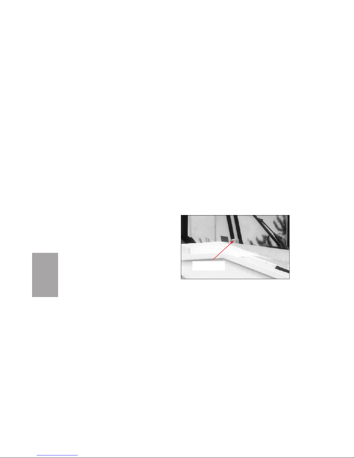
9. During sweeping, monitor the level of water in
the spray water tank. Sweeping without water
will result in poor dust suppression. The
water gauge is located in front of the right
windshield (Figure O-7).
10. If necessary, turn on lights using:
Hazard switch (33, Figure O-1)
Head Lights switch (35)
Broom Light switch(es) (29 and/or 43)
Beacon switch (optional) (34)
Rear Flood switch (optional) (37).
11. Use the Engine Throttle Control (53, Figure
O-2) to set the recommended engine speed
OPERATION
O-14
Area In Front Of Windshield
Figure O-7
SPRAY WATER
GAUGE
Page 47

according to sweeping conditions. See Table
O-1.
12. Ensure that the front of the machine is clear
before moving it forward. During operation of
the sweeper, monitor the front round mirrors
for people outside of your direct field of view.
When sweeping, to keep the sweeper evenly aligned
with the curb, choose a focal point on the front of
the sweeper, such as the edge of the mirror or a
place on the hopper, and line it up with the edge of
the curb ahead of the sweeper. This eliminates any
tendency to oversteer the sweeper.
CAUTION
Do not lean out the opened bubble window
while sweeping. Doing so may result in injury
by low-hanging branches, etc.
The side mirror must be correctly adjusted to view
side broom operation and location.
!
O-15
OPERATION
Sweeping Engine Sweeper
Conditions Speed, Speed,
RPM MPH
Light 1500 rpm 5-7
(8-11 km/h)
Medium 1800 rpm 3-5
(5-8 km/h)
Heavy 2100 rpm 2-4
(3-6 km/h)
Table O-1
General Sweeping Guidelines
Page 48
While sweeping light material like leaves, if the
sweeper starts pushing a pile of the material,
sweeping may be improved by raising the conveyor
slightly. To make this change, tap the MB / Conv
Height switch (50, Figure O-1).
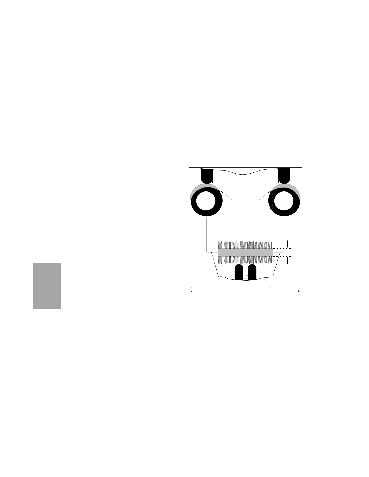
SWEEPING PATTERNS
Broom sweeping patterns are a guideline of sweeping performance. Patterns should be checked daily.
A pattern may be wrong because of incorrect broom
downpressure, incorrect broom angle, or excessive
broom wear.
A pattern narrower than that in Figure O-8 indicates that there is too little downpressure, which
will result in poor sweeping performance. A pattern
wider than the diagram indicates excessive downpressure, which will cause the broom to wear too
fast.
If a side broom is set too flat, debris will be scattered instead of being directed to the path of the
OPERATION
O-16
Pelican P Broom Patterns
Figure O-8
One broom 8 ft (2438 mm)
Two brooms 10 ft (3048 mm)
Side Broom Patterns
(Must overlap
Main Broom Pattern)
Main Broom Pattern
4" to 6"
Sweeping Paths:
Page 49

conveyor. If a side broom is tilted at too large an
angle, debris will trail or be scattered, and the
broom will wear too fast. If the main broom is not
kept parallel to the swept surface, the broom will
wear into a coned (tapered) shape and will give
poor sweeping performance.
If a broom’s bristles have worn to less than half of
their original length, the broom will produce a
small pattern and poor sweeping performance.
To check the broom patterns:
1. Make sure that the tires are inflated to the
correct pressure.
2. Park the sweeper on a level, paved surface.
3. Using the MB / Conv Height switch (50, Figure
O-1) and the Broom Height switch(es) (26
and/or 46), lower the main broom and side
broom(s).
4. As necessary, use the Broom Rotate switches
(22, 27, 45) to start rotation of the brooms.
5. Using the Engine Throttle Control knob (53,
Figure O-2), increase engine speed to about
2500 rpm.
6. Sweep in one spot for about 15 seconds.
7. Stop broom rotation by using the Broom
Rotate switches (22, 27, and/or 45, Figure O-1).
8. Use the Broom Height switch(es) (26 and/or
46) to raise the side brooms.
9. If the sweeper has standard main broom suspension, use the MB / Conv Height switch (50)
to raise the main broom.
If the sweeper has hydraulic main broom suspension, use the CONV LOWER / MB/CONV
UP switch (47) to raise the main broom.
10. Drive forward far enough to reveal the patterns left on the pavement by the brooms.
11. Check that the side broom patterns are crescent-shaped and approximately 4 inches wide
O-17
OPERATION
Page 50
at the top. The patterns should overlap the
path of the main broom (Figure O-8).
12. Check that the main broom pattern is of an
even width along its whole length (does not
taper). The pattern should be 4 to 6 inches (10
to 15 cm) wide. After sweeping, the broom bristle tips should have an even amount of dirt on
all of them.
If the patterns do not conform to those in Figure O8, adjust or replace the brooms, as necessary, by the
procedures in the Service Procedures section.
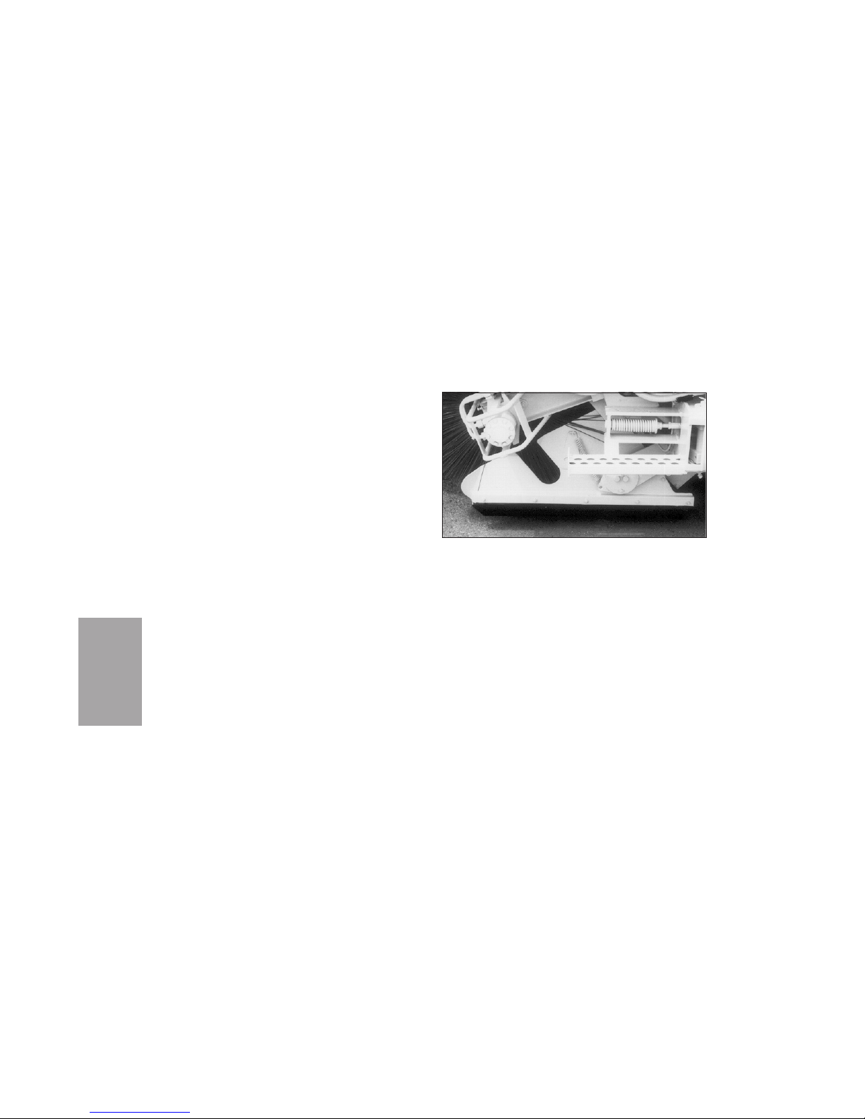
While checking the broom patterns, also check the
dirt shoe (Figure O-9) on each side of the main
broom. The dirt shoe housings should be flush with
the main broom. The shoes should be level with the
ground.
Procedures for adjusting the shoes are in the
Service Procedures Section.
REVERSING THE CONVEYOR
The conveyor may be reversed, if necessary, for
example, during washdown or if an object is
jammed in the conveyor.
OPERATION
O-18
Dirt Shoe
Figure O-9
Page 51

NOTICE
Do not operate the conveyor in reverse for more than
15 seconds. Doing so may cause misalignment of the
conveyor belt and subsequent damage.
To reverse the conveyor, take the following steps.
1. Slow the engine.
2. Press the 3-position Conveyor Rotate switch
(49, Figure O-1) to Off until the conveyor
stops.
3. Press the switch to Reverse just long enough
to remove the jammed object.
DUMPING THE HOPPER
DANGER
Raise or dump hopper in areas free of power
lines. Before raising or tilting hopper, check
for adequate overhead and forward clearance.
Raise hopper only in areas with minimum
overhead clearance of 16 ft (5 m) and forward
clearance of 3 ft (1 m). Do not raise hopper
while under trees, bridges, etc.
CAUTION
Overloading the hopper can cause personal
injury or damage to the sweeper. Dump the
hopper frequently when loading heavy materials.
1. Come to a complete stop on level surface.
2. Stop rotation of conveyor by using Conveyor
Rotate switch (49, Figure O-1).
3. As necessary, stop rotation of broom(s) by
using Broom Rotate switches (22, 27, 45).
4. Raise side broom(s) by using Broom Height
switches (26 and/or 46).
5. If sweeper has standard main broom suspension, use MB / Conv Height switch (50) to raise
main broom and conveyor.
If sweeper has hydraulic main broom suspen-
!
!
O-19
OPERATION
Page 52
sion, use CONV LOWER / MB/CONV UP
switch (47) to raise main broom and conveyor.
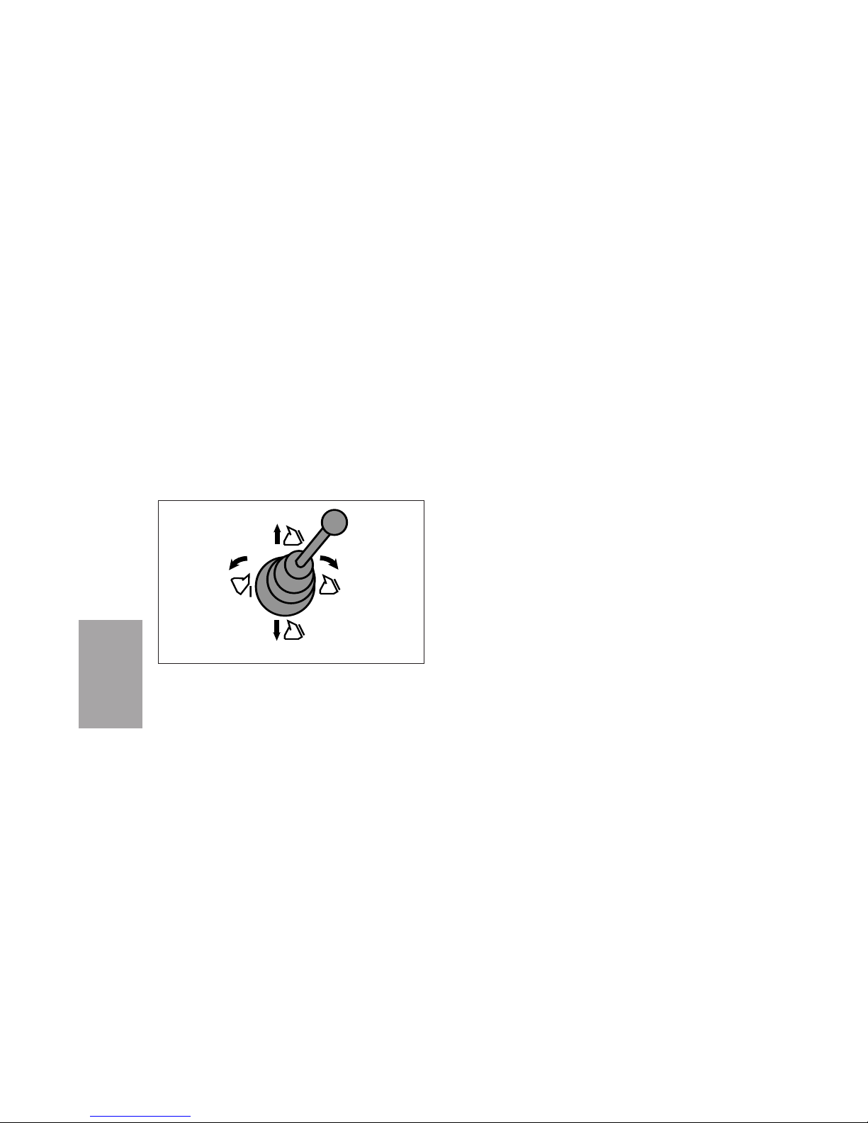
6. Use the Hopper Dump Control (Figure O-10) to
control hopper raising and rollout.
To raise hopper: move control forward
To lower hopper: move control back
To roll out hopper: move control to left
To roll back hopper: move control to right
Hopper requires alternate operation of raise
and rollout functions. Be careful not to roll out
hopper too far until sweeper is in position to
dump hopper.
7. Keep hopper level until in position for dumping.
8. If dumping into truck:
Raise hopper to full height by moving
control forward
Slowly approach truck
When properly positioned behind truck, roll
out hopper by moving control to left
9. Roll hopper all the way back by moving control
to right.
10. Back sweeper away from truck.
11. Lower hopper by moving control to rear.
OPERATION
O-20
Raise
Lower
Roll
out
Roll
back
Hopper Dump Control
Figure O-10
Page 53

SHUTTING DOWN THE UNIT
1. Park the sweeper.
2. Use the Engine Throttle Control (53, Figure
O-2) to set engine speed to idle (about 1000
RPM).
3. Set the parking brake.
4. Stop rotation of the conveyor by using the
Conveyor Rotate switch (49, Figure O-1).
5. As necessary, stop rotation of the brooms by
using the Broom Rotate switches (22, 27, 45).
6. Raise the side broom(s) by using the Broom
Height switches (26 and/or 46).
7. If the sweeper has standard main broom suspension, use the MB / Conv Height switch (50)
to raise the main broom and conveyor.
If the sweeper has hydraulic main broom suspension, use the CONV LOWER / MB/CONV
UP switch (47) to raise the main broom and
conveyor.
NOTICE
Before shutdown, the engine must be run at idle
speed (about 1000 RPM) for at least 2 minutes to
cool hot engine parts. Idling time lets the oil and
coolant cool the turbocharger, cylinders, bearings,
etc.
8. After the engine has idled long enough, use the
Ignition switch (23) to shut down the engine.
The length of time needed to cool the hot
engine parts depends on the air temperature
and the temperature of the engine when the
sweeper was parked.
AT END OF SHIFT
For continued high performance, the sweeper must
be thoroughly washed down at the end of each shift
by the procedure in the Maintenance section.
O-21
OPERATION
Page 54

After washdown is complete, maintenance must be
performed as directed in the Maintenance and
Service Procedures sections.
Filling the fuel tank at the end of the shift will
force most of the air out of the tank. This action
will minimize the water condensation that can happen in the air space as the tank cools.
OPERATION
O-22
Page 55

SCHEDULED MAINTENANCE
Wash down machine after every sweeping
shift. See Daily Washdown procedure later in
this chapter.
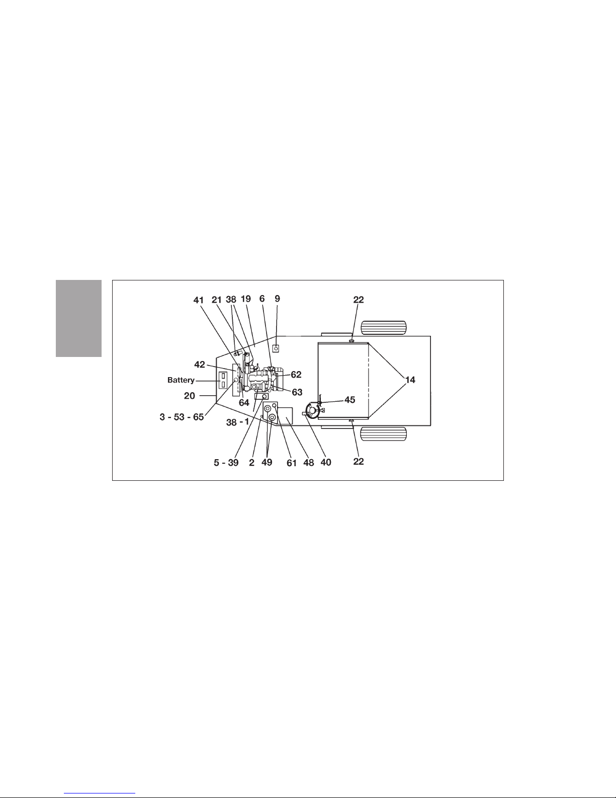
DAILY SERVICE CHECKLIST
The numbers below correspond with the locations on
Figures M-1, M-2, M-3 and M-4.
Service after every shift or 10 hours
1 Check Engine Oil Level - Oil Pressure Gauge
2 Check Hydraulic Oil Level - Sight Tube
3 Check Radiator Coolant Level
4 Check Tire Inflation Pressure
5 Inspect Pre-Cleaner - Air Filter (Accessory)
6 Drain Water Separator - Engine
8 Wash Down Entire Machine - Flush Out Lower
Conveyor Roller
9 Check Windshield Washer Fluid Level
10 Grease Main Broom Bearings (2)
11 Grease Main Broom Pulley & Cylinder (2)
13 Grease Lower Conveyor Roller Bearings (2)
14 Grease Upper Conveyor Roller Bearings (2)
15 Grease Dirt Shoe Pivot Plate (6)
16 Grease Dirt Shoe Pivot (2)
17 Grease Sprung Guide Wheel
18 Grease Main Broom Cam Follower (2)
19 Inspect Water Filter
20 Check backup alarm operation
M-1
MAINTENANCE
MAINTENANCE
Page 56

MAINTENANCE
M-2
PERIODIC SERVICE CHECKLIST
The numbers below correspond with the locations on
Figures M-1, M-2, M-3 and M-4.
Service after 50 hours
21 Inspect Spray Water Pump
22 Grease Conveyor Pivot (2)
24 Grease Main Broom Cam Pivot (2)
25 Grease Side Broom Turnbuckle
26 Grease Side Broom Kick-Back Bearing
27 Grease Side Broom Lift Bearing
28 Grease Side Broom Lift Cylinder Pivot
29 Grease Side Broom Lift Rod Clevis
30 Grease Side Broom Bell Crank Bearings (2)
31 Grease Side Broom Pivot Pin
32 Grease Hopper Arm Pivot (18)
33 Grease Link Weldment Pivot Point
Service after 150 hours
38 Replace Engine Oil & Filter
39 Inspect Engine Air Intake System (Any Time
Indicator Lights)
40 Check Brake Master Cylinder Fluid Level
41 Inspect Engine Drive Belts
42 Inspect & Clean Radiator Cooling Fins
43 Grease Guide Wheel Pivot Bearing
44 Grease Guide Wheel Bearing Hub (2)
45 Grease Foot Control Rod End
Page 57

M-3
MAINTENANCE
Service after 500 hours
48 Drain & Flush Hydraulic Oil Reservoir
49 Replace Hydraulic Oil Filter (2) (Any Time
Indicator Lights)
53 Check Anti-Freeze
54 Check Oil Level In Hubs
Service after 1000 hours
61 Change Hydraulic Oil Reservoir Breather
62 Adjust Valve Clearance
63 Inspect Turbocharger
64 Inspect Engine Fan Hub
65 Change/Flush Coolant - Ethylene Glycol Anti-
Freeze
After 1000 hours, change oil in torque hubs.
After 5000 hours or 5 years (whichever occurs first),
or when servicing the guide wheel as a result of
impact damage, replace the guide wheel pivot pin.
Examples of impact damage might be, but are not
limited to: Bent rim, tire damage, axle damage, etc.
Contact Elgin dealer with any questions.
Page 58
MAINTENANCE
M-4
Pelican P Top View - Scheduled Maintenance Items
Figure M-1
Page 59
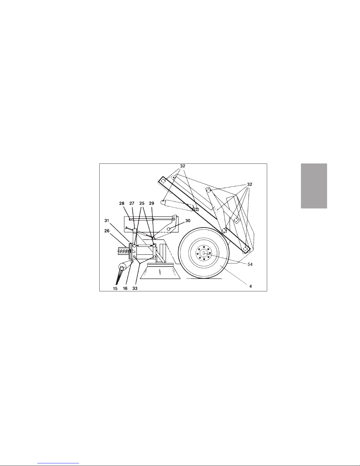
M-5
MAINTENANCE
Pelican P Front End - Scheduled Maintenance Items
Figure M-2
Page 60
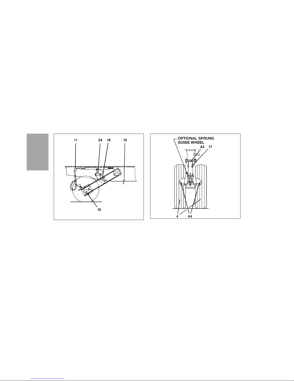
MAINTENANCE
M-6
Pelican P Rear End - Scheduled Maintenance
Figure M-3
Pelican P Guide Wheel
Figure M-4
Page 61
DAILY WASHDOWN
Washdown after each sweeping shift is essential to
good sweeper maintenance. Follow the procedure
below for complete, effective cleaning.
1. Park the sweeper on a flat, level surface, away
from power lines, trees, etc.
WARNING
DO NOT work under or around a raised hopper. The best way to get safe access to the
machine behind the hopper is the roll-out
method described below.
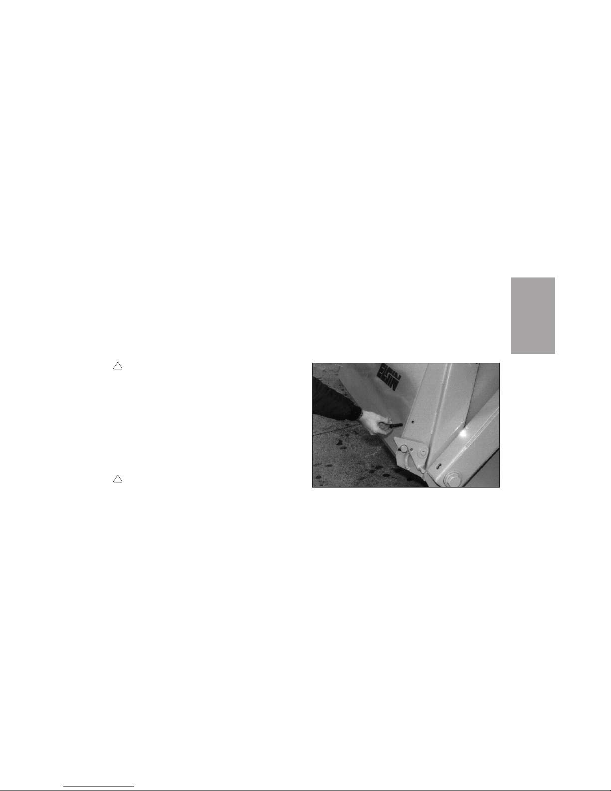
2. Install a 1/2 x 2-1/2 inch bolt in each of the two
holes located above the spring-loaded door
latches on the sides of the hopper (Figure M-5).
The bolts will hold the hopper door closed during roll-out.
DANGER
Raise or dump hopper in areas free of power
lines. Before raising or tilting hopper, check
for adequate overhead and forward clearance.
Raise hopper only in areas with minimum
overhead clearance of 16 ft (5 m) and forward
clearance of 3 ft (1 m). Do not raise hopper
while under trees, bridges, etc.
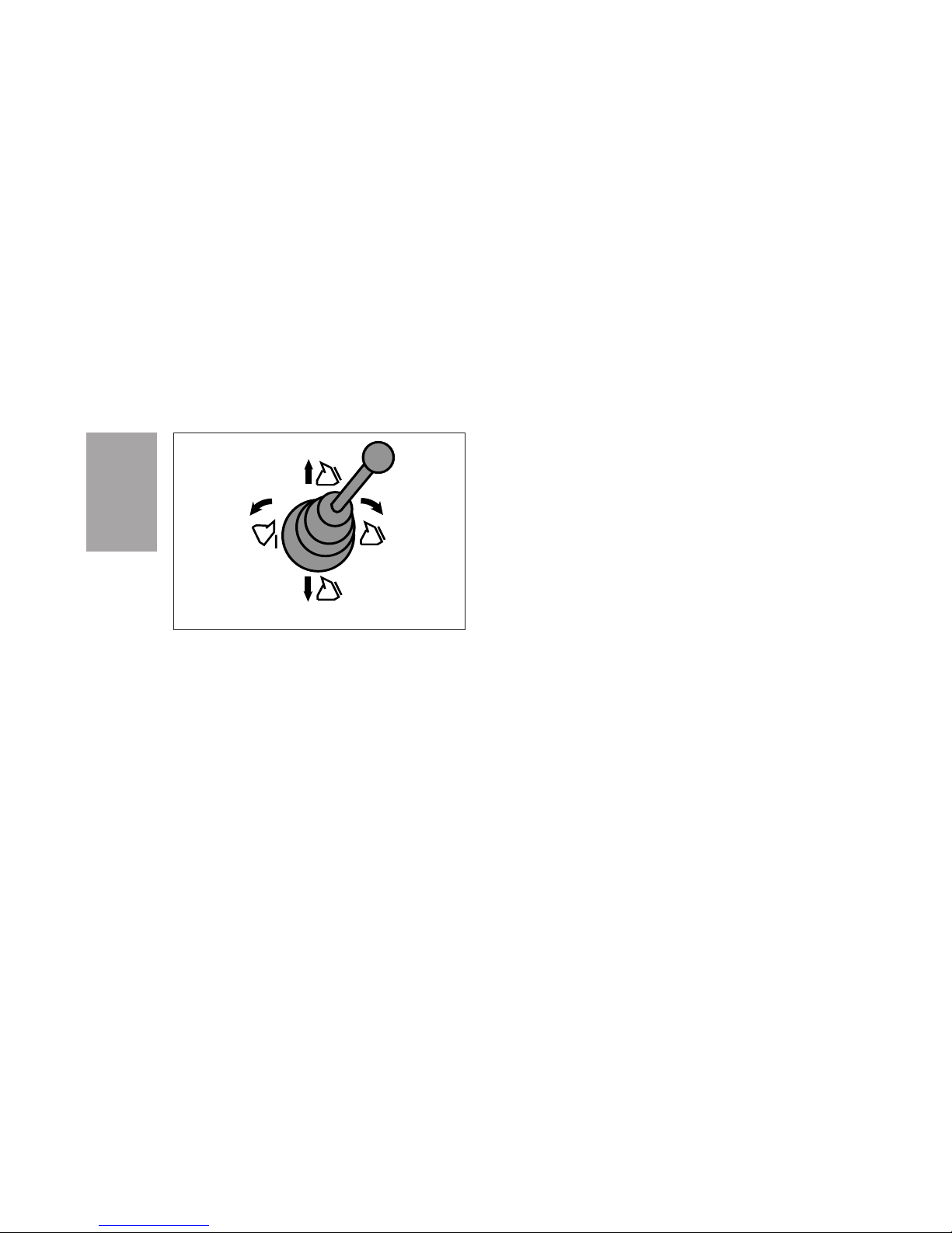
3. Raise and roll out the hopper using the Hopper
Dump Control on the Control Console (Figure
M-6).
!
!
M-7
MAINTENANCE
Locking Hopper Door For Roll-Out
Figure M-5
Page 62
4. When the hopper reaches the limit of its
motion, carefully lower the hopper completely
to the ground or pavement.
5. Lower the main broom, conveyor and side
broom(s) to sweeping positions. Start rotation
of the main broom and conveyor.
6. Fill the water tank to overflowing, allowing the
water to flush the conveyor belt for one to two
minutes. Reverse the conveyor several times
during this flushing.
7. With the conveyor still running forward, use
high pressure water to flush the conveyor and
belt backing plate.
8. Flush out the hopper, all undercarriage parts,
side broom(s), dirt deflectors and dirt shoes.
9. Reverse the conveyor for no more than 30 sec-
onds and use high pressure water to dislodge
material between roll and edge of scraper bar.
10. Washdown exterior of sweeper, including lights,
mirrors, and safety decals.
MAINTENANCE
M-8
Raise
Lower
Roll
out
Roll
back
Hopper Dump Control
Figure M-6
Page 63
NOTICE
Never steam clean or wash an engine while it is
running. Water can cause a hot manifold to crack.
11. After engine has cooled, washdown engine
compartment, including engine radiator and
oil cooler.
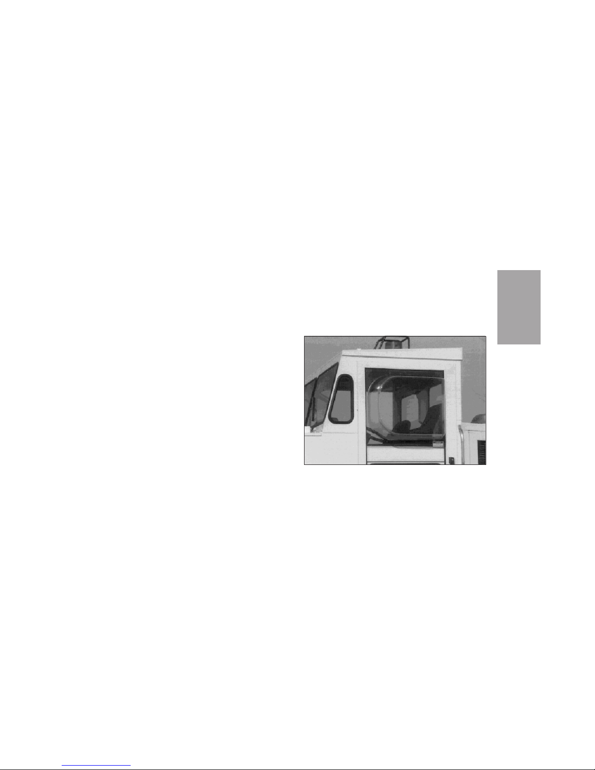
BUBBLE WINDOW
MAINTENANCE
To avoid having the bubble window (Figure M-7)
turn milky with age, use an acrylic cleaner, such as
the one shipped with the Pelican. Apply the cleaner
to a rag and wipe it on the window.
NOTICE
Use a soft cloth on the bubble window. Do not use
coarse materials, such as paper towels on the bubble
window.
If the bubble window begins to turn milky, clarity
may be restored by the following method:
1. Thoroughly clean the window with ammonia
and water, being sure to remove all dirt that
may be embedded in scratches or cracks.
2. Rinse the window completely and allow it to
dry.
M-9
MAINTENANCE
Pelican Cab Bubble Window
Figure M-7
Page 64

3. After window is completely dry, apply a goodquality floor wax with a poly base. This will fill
in any scratches and restore the clarity of the
window.
To avoid cracking the bubble window, always use
the latches on the inside of the cab to close the window. Do not apply force to the window itself.
LUBRICATION
AUTOMATIC LUBRICATION
If the sweeper is equipped with the optional automatic lubrication system, the system and the bearings it serves should be inspected periodically as
recommended in the manual from the system manufacturer.
TORQUE HUB OIL
Oil level and type may vary with specific torque
hub model and application.
Type
SAE 80W-90
On applications where the lubricant must meet
special requirements, a suitable substitute may be
used. Contact Elgin Sweeper Company regarding
special lubrication needs.
Oil Temperature
Continuous - 160°F (70°C)
Intermittent - 200°F (95°C)
Oil Change Schedule
Initial - After 50 hours of operation
Subsequent - After 1000 hours or one year,
whichever comes first.
MAINTENANCE
M-10
Page 65
Higher temperatures may make it necessary to
change oil more frequently.
Oil Fill Level and Volume
Unit should be half full. Approximate volume of
hub is 37 oz (1.1 L).
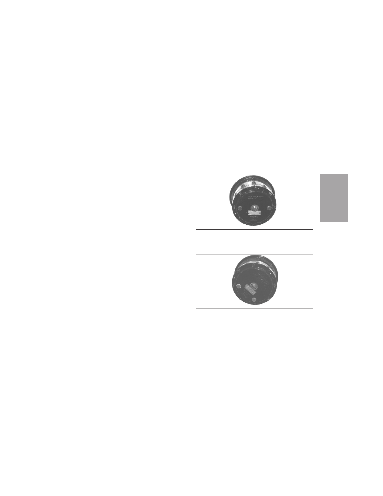
To check oil level:
• For a hub with oil plugs 180º apart (Figure M-8),
turn the hub until the plugs are level with the
disconnect cover.
• For a hub with oil plugs 90º apart (Figure M-9),
turn the hub until the check plug is level with
the disconnect cover.
To drain oil, turn hub until one plug is at the bottom.
M-11
MAINTENANCE
Torque Hub
Figure M-9
Torque Hub
Figure M-8
Page 66

NOTES:
MAINTENANCE
M-12
Page 67
TOWING
NOTICE
Towing with hubs engaged will damage hydrostatic
drive.
In all cases the procedure below must be followed,
proper equipment must be used, and all laws applying to vehicles in tow must be obeyed.
CAUTION
Never tow the sweeper faster than 20 mph
(32 km/h).
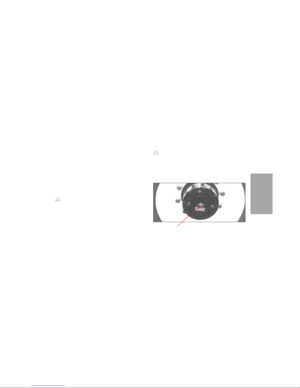
The Pelican may be towed from the rear with the
drive wheels on the ground after disengaging the
torque hubs (Figure SP-1) on both sides.
To tow the Pelican:
1. Set parking brake.
WARNING
The drive wheels must be blocked, before you
prepare the sweeper for towing.
2. Block drive wheels, so sweeper cannot roll forward or backward.
!
!
SP-1
SERVICE
PROCEDURES
SERVICE PROCEDURES
DISCONNECT CAP
Torque hub
Figure SP-1
Page 68

CAUTION
Disconnect cover should be removed carefully
to prevent injury by spring-loaded pin or loss
of pin. Pin may press out on cover continuously or may catch and then spring out suddenly.
3. At each drive wheel, take the following steps.
a. Carefully remove two screws and discon-
nect cover from hub (Figure SP-1).
b. Reverse disconnect cover to push tow pin
in and disengage hub. Pin must be pushed
to inner position to prevent damage.
c. Secure cover with screws.
4. Connect rear of sweeper to towing vehicle.
WARNING
Make sure the sweeper will not roll out of control, before you unblock the wheels.
5. Unblock wheels.
6. Release parking brake before towing Pelican.
After towing is completed, take the following steps.
1. Set parking brake.
WARNING
The drive wheels must be blocked, before the
sweeper is disconnected from the towing
vehicle.
2. Block drive wheels, so sweeper cannot roll forward or backward.
3. Disconnect sweeper from towing vehicle.
CAUTION
Disconnect cover should be removed carefully
to prevent injury by spring-loaded pin or loss
of pin. Pin may press out on cover continuously or may catch and then spring out suddenly.
!!!
!
SERVICE
PROCEDURES
SP-2
Page 69

NOTICE
Hydrostatic drive system must not be operated with
either tow pin in “tow” position (the inner position).
Damage to shaft and splines may result.
4. At each drive wheel, take the following steps.
a. Carefully remove two screws and discon-
nect cover from hub (Figure SP-1) to let
tow pin move out and engage hub.
NOTICE
If a tow pin does not pop out, it can be
made to do so by rocking the sweeper backward and forward or by jacking up the
front of the sweeper and turning the drive
wheel. If a jack must be used, see Wheels
And Tires in this section of the manual.
b. Reverse disconnect cover, so it will hold
tow pin in outer position.
c. Secure cover with screws.
WARNING
Make sure sweeper will not roll out of control,
before you unblock the wheels.
5. Unblock wheels.
AIR CLEANER
The engine is equipped with a dual-element, drytype air cleaner with an automatic rubber unloader
(dump) valve (Figure SP-2). A sensor in the air
cleaner signals when air flow is restricted, causing
the air filter restriction indicator to light on the
control console. This indication alerts the operator
that the air filter needs servicing.
NOTICE
Do not open the air cleaner unless the indicator
lights or weak engine performance suggests a lack of
air supply.
To service the air cleaner, use the following
procedure:
!
SP-3
SERVICE
PROCEDURES
Page 70

1. Remove the cover from the filter canister.
2. Remove and discard the outer element.
NOTICE
A dirty element should always be discarded, not
cleaned for further use. Cleaning an element voids
the warranty and makes the element less effective.
3. Visually check the rubber unloader valve, and
pinch the lips of the valve to remove any accumulation of debris. If the unloader is damaged,
install a new unloader.
4. Clean the inside of the air cleaner canister
with a damp, lint-free cloth.
5. Install a new outer element.
6. Securely fasten the cover on the filter canister
with the unloader at the bottom. Make sure all
clamps are correctly fastened.
7. With the engine operating, check the air filter
restriction indicator. If the indicator stays off,
air cleaner service is complete. If the indicator
lights, go to step 8.
8. With the engine shut down, open the air
cleaner.
SERVICE
PROCEDURES
SP-4
Air Cleaner Assembly
Figure SP-2
Page 71

9. Remove and save the outer element, taking
care to keep the element clean and to avoid
any damage to the element.
NOTICE
A damaged outer element, or one with a loose, damaged, or missing seal, will allow dust to clog the
inner element.
10. Remove and discard the inner element.
11. Install a new inner element and the saved
outer element, making sure they are correctly
seated.
NOTICE
To prevent damage, the elements must be completely
seated before the canister cover is installed.
12. Securely fasten the cover on the filter canister
with the unloader at the bottom. Make sure all
clamps are correctly fastened.
13. Check the whole air intake system for leaks.
FUEL SYSTEM
The fuel lift pump (C, Figure SP-3) draws fuel from
the fuel tank (K) and pushes it through the fuel filters (G) to the injection pump (A). The injection
pump forces fuel through the injectors (E), which
atomize the fuel and spray it into the combustion
chamber of each cylinder. The low pressure leakoff return line (H) from the injection pump passes
through each injector and returns to the fuel tank.
DRAINING FUEL WATER
SEPARATOR
The water separator on the bottom of the fuel filter
(Figure SP-4) should be checked daily and drained
when needed. Frequency of draining will be determined by operating conditions and quality of the
fuel.
To drain the separator, use the following procedure.
SP-5
SERVICE
PROCEDURES
Page 72
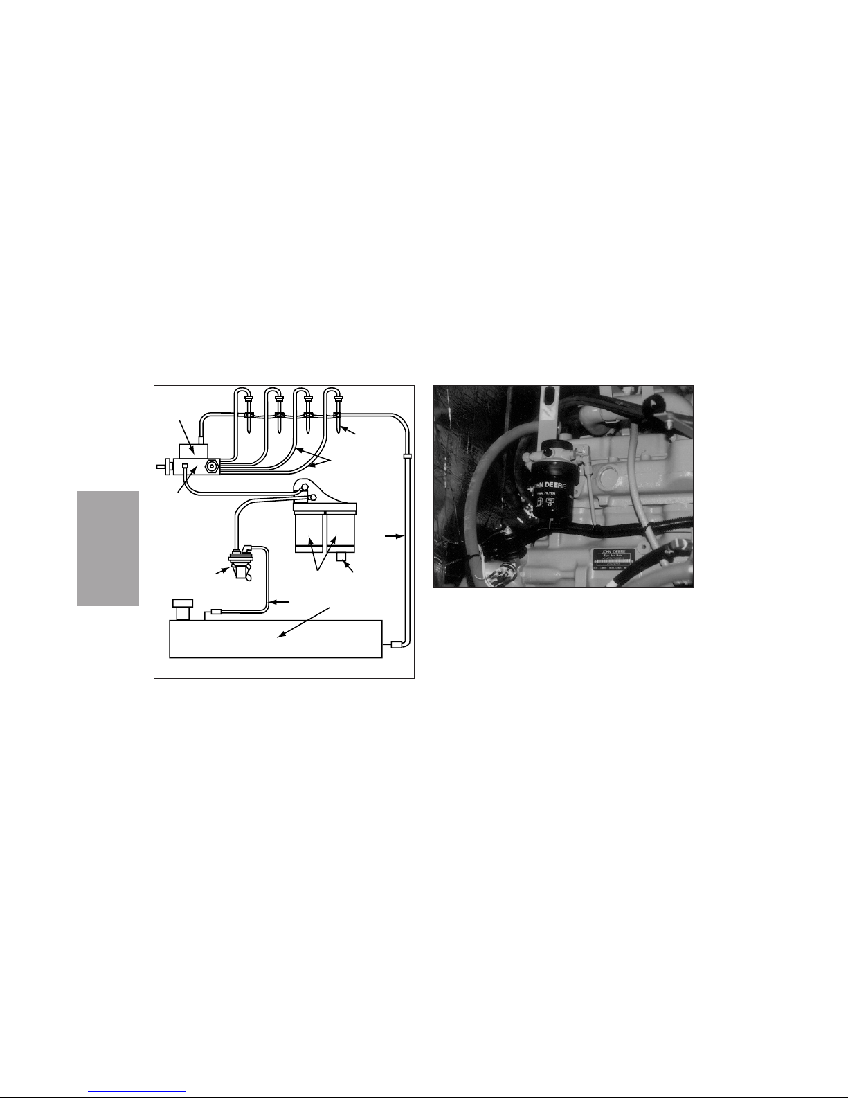
1. Remove the drain plug from the bottom of the
filter.
2. Loosen the bleed screw.
SERVICE
PROCEDURES
SP-6
Fuel Filter
Figure SP-4
B
A
E
C
H
D
J
K
G
F
Fuel System
Figure SP-3
Page 73

3. Allow the water and any contaminated fuel to
drain into a pan.
NOTICE
The presence of a large amount of water in the filter
may indicate that water should be drained from the
fuel tank. If so, the cause of the water build-up
should be found.
4. Install and tighten the drain plug. Drain must
always be closed before starting the engine.
5. Bleed air from the fuel system by following the
instructions in the operator manual supplied
by the engine manufacturer.
6. Start the engine, then make sure that no fuel is
leaking from the filter.
CHANGING FUEL FILTER
To change the fuel filter (Figure SP-4), use the following procedure.
1. Turn the filter cartridge to remove it from the
filter head.
NOTICE
The presence of a large amount of water in the filter
may indicate that water should be drained from the
fuel tank. If so, the cause of the water build-up
should be found.
2. Inspect the filter for water build-up, then discard it.
3. Clean the filter sealing surface.
4. Apply a light coat of engine oil to the surface of
the filter gasket.
5. Install a new filter cartridge in the filter head.
6. Bleed air from the fuel system by following the
instructions in the operator manual supplied by
the engine manufacturer.
SP-7
SERVICE
PROCEDURES
Page 74
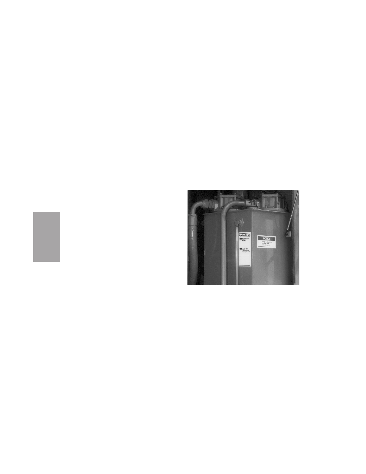
BLEEDING FUEL SYSTEM
Air must be removed from the fuel system after the
system has been opened or the engine has run out
of fuel.
To bleed air from the fuel system, follow the directions in the operator’s manual supplied by the
engine manufacturer.
HYDRAULIC SYSTEM
The hydraulic system of the Pelican P is spline
shaft driven. There are no belts to break or pulleys
to adjust.
There are three basic hydraulic systems:
hydrostatic drive system
hydraulic sweep system
hydraulic steering system.
All three systems share a common hydraulic oil
tank with two filters (Figure SP-5). The tank is
located next to the engine on the right hand side of
the sweeper. With the hopper down, check the oil
level at the sight gauge on the side of the tank.
SERVICE
PROCEDURES
SP-8
Hydraulic Tank And Filters
Figure SP-5
Page 75
NOTICE
Elgin Sweeper Company recommends Shell Tellus
T 68 or equivalent hydraulic oil. Never mix different
kinds of hydraulic oil.
Use new, clean hydraulic oil that meets all Elgin
Sweeper Company requirements. Never mix different types of oil. When adding oil, remove the plug
on the top of the return filter and add oil. This will
prefilter the oil added to the tank.
Every 500 hours of operation, drain the tank, put
in new hydraulic oil, and replace the hydraulic filter elements with new elements. (Never try to clean
an element for further use.) Every 1000 hours,
replace the hydraulic tank breather with a new
one.
SPRAY WATER SYSTEM
Spray water is used during sweeping to suppress
dust and to moisten the debris for better settling in
the hopper.
A fill hose is stored in the front fender (Figure
SP-6). Before filling the water tank(s), always allow
the hydrant to run to flush out any sediment or
debris in the hydrant.
Water for the spray water system passes through a
100 mesh filter prior to entering the water
pump.This stainless steel strainer filter is located
under the removable left hand side panel. A shutoff
SP-9
SERVICE
PROCEDURES
Fill Hose
Figure SP-6
Page 76
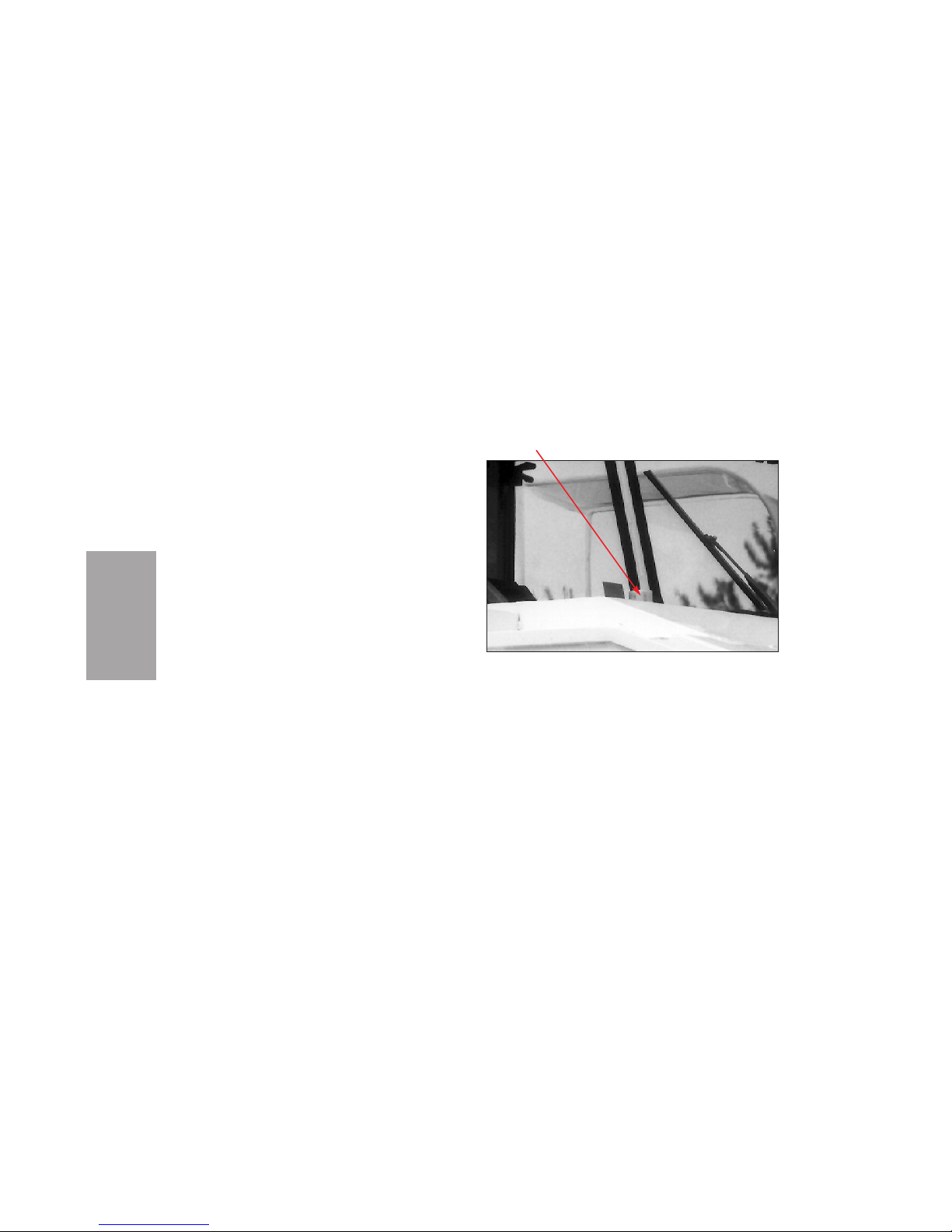
valve is located between the water filter and the
water tank. This should be turned off to stop water
from flowing out of the tank when the filter screen
is removed for daily cleaning. The filter should be
changed only if it has been damaged.
A mechanical water level gauge (Figure SP-7) is
visible through the right windshield.
The flow of water is controlled through switches
and a valve at the control console in the cab, as
detailed in the Operation section of this manual.
BROOM ADJUSTMENT
Broom sweeping patterns are a guideline of sweeping performance. Patterns should be checked daily
according to the procedure in Operation section of
this manual. If the patterns do not conform to those
shown in the Operation section, correct the patterns by using the following procedures, as needed.
SERVICE
PROCEDURES
SP-10
Area In Front Of Windshield
Figure SP-7
SPRAY WATER
GAUGE
Page 77
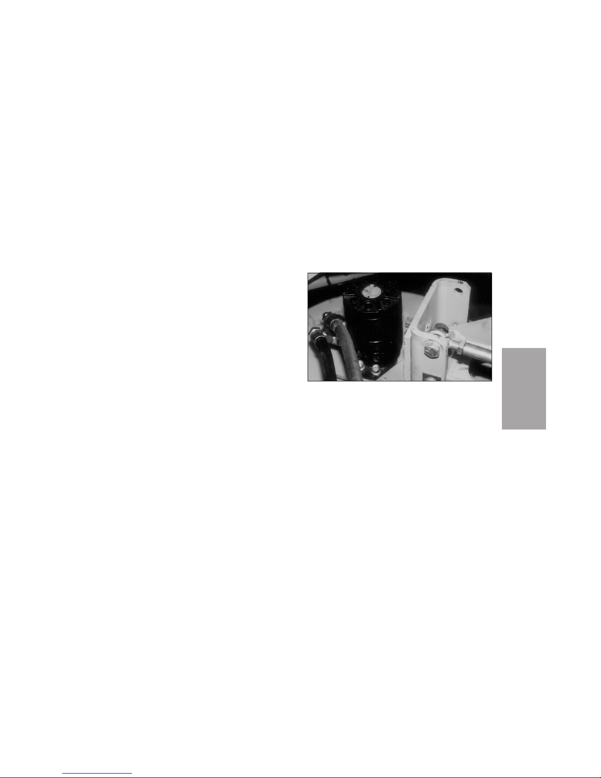
SIDE BROOM ADJUSTMENT
Side-To-Side Angle
To correct the side-to-side angle, take the following
steps.
1. With the side broom down and extended, loosen
the two bolts that attach the motor bracket to
the forward side broom bracket (Figure SP-8).
2. Tilt the assembly to the proper angle.
3. Tighten the bolts.
Front-To-Back Angle
To correct the front-to-back angle, take the following steps.
1. Loosen the turnbuckle jam nut located on the
upper broom suspension (Figure SP-9).
SP-11
SERVICE
PROCEDURES
Side Broom Bracket
Figure SP-8
Page 78
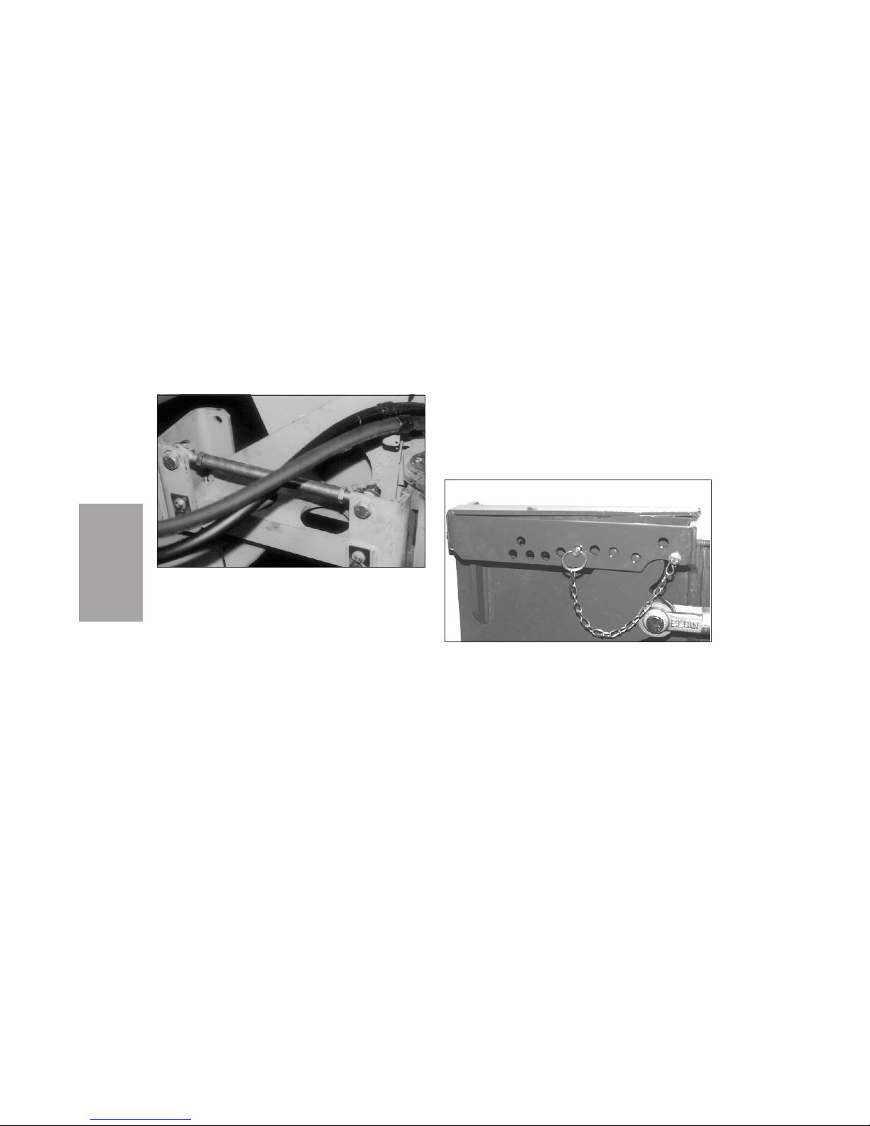
2. Rotate the turnbuckle to adjust the broom
angle.
3. Tighten the turnbuckle jam nut.
Down Pressure
To correct the side broom down pressure, reset the
position of the quick-release pin located on the
adjustable stop (Figure SP-10).
SERVICE
PROCEDURES
SP-12
Side Broom Turnbuckle
Figure SP-9
Down Pressure Adjustment
Figure SP-10
Page 79
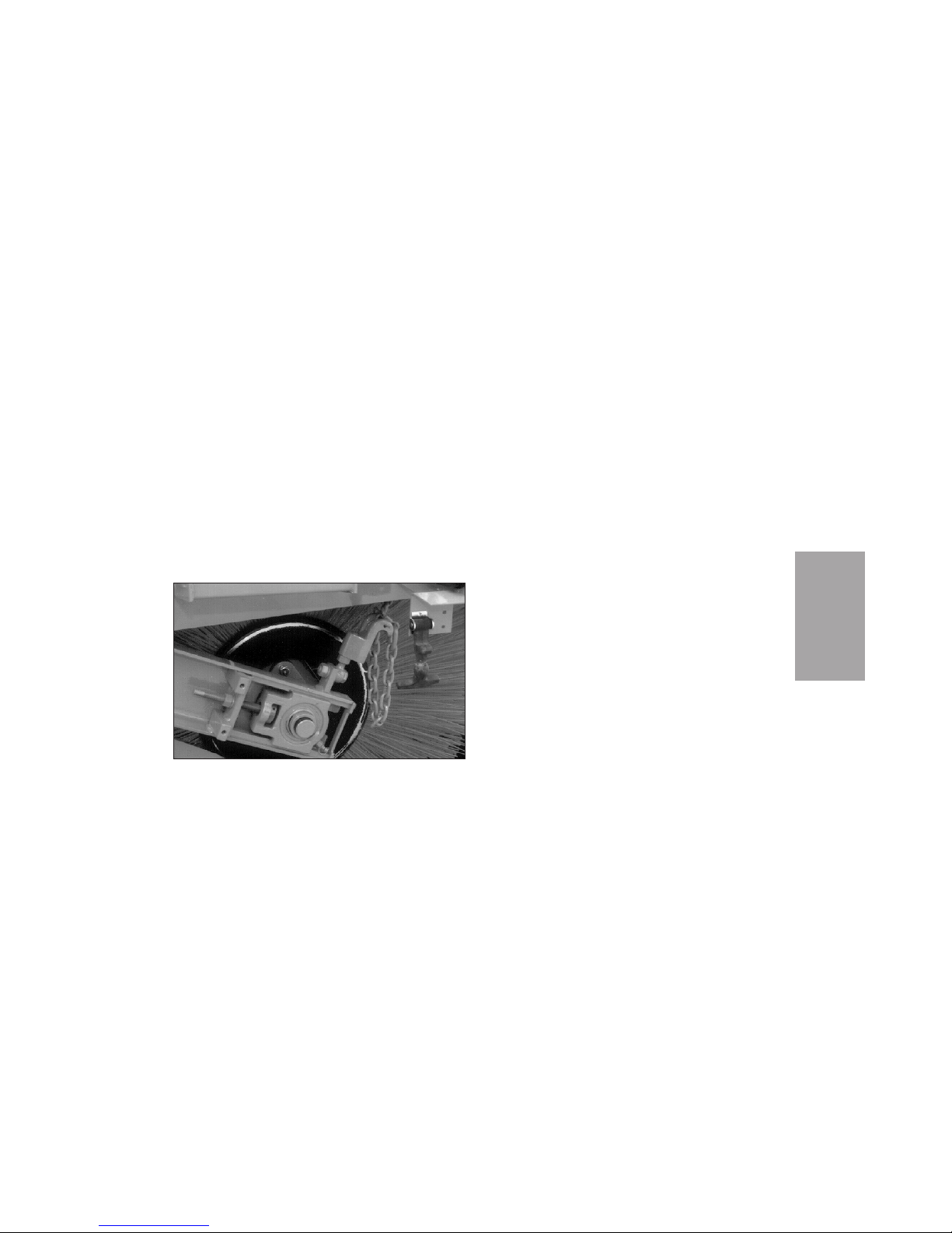
MAIN BROOM ADJUSTMENT
Standard (Chain) Suspension
To adjust the main broom contact area with a chain
suspension (Figure SP-11), take the following steps.
1. Lower the main broom on a flat, level surface.
2. Adjust the spring tension on one side as necessary using the chain. For example, if the left
side shows more wear (or taper) than the right
side, shorten the chain on the left side to raise
the left side of the broom.
Hydraulic Suspension
In the optional hydraulic main broom suspension
(Figure SP-12), the snubbing spring is compressed
or released to adjust for even broom wear. The factory adjustment for the left side is approximately
3.75 in, for the right 1.25 in. This counterbalances
the added weight of the drive motor on the right
side.
If the left side shows more wear than the right
side, raise the left side.
To adjust the main broom contact area with the
optional hydraulic suspension, use the following
procedure:
1. Lower the main broom on a flat, level surface.
SP-13
SERVICE
PROCEDURES
Main Broom Chain Suspension
Figure SP-11
Page 80
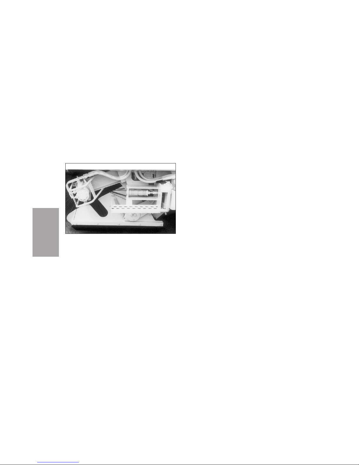
2. Loosen the jam nut.
3. Turn the adjusting nut up or down as needed. If
the adjusting nut does not want to turn, a little
oil on the nut and collar will help. Two complete turns of the adjusting nut will result in
about 1” of change in the taper (the difference
in diameter between the ends of the broom).
4. Tighten the jam nut.
DIRT SHOE ADJUSTMENT
Dirt shoes ride perpendicular to the ground to act
as a guide to keep debris between the main broom
and the conveyor.
The main broom rotates between the two dirt
shoes. Wings at the rear of each dirt shoe assure
that the bristles are turned in and ride flush within
the dirt shoe housings.
Both dirt shoes (Figure SP-13) should be correctly
aligned and ride level with the surface of the road.
If they are not correctly positioned, this should be
corrected immediately.
To check for proper dirt shoe adjustment, use the
following procedure.
1. Lower the main broom.
2. Start main broom rotation.
SERVICE
PROCEDURES
SP-14
Hydraulic Main Broom Suspension
Figure SP-12
Page 81
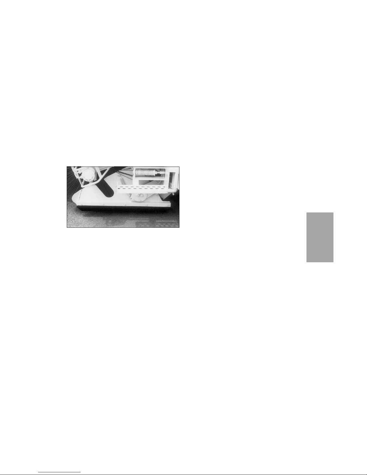
3. Drive the sweeper forward to allow brooms to
attain proper sweeping position.
4. Visually inspect the rotation of the main broom
between the dirt shoes.
5. Raise the broom and drive forward to allow
components to attain transport position. In
raised transport position the dirt shoes should
be parallel to, but not touching the ground.
If the dirt shoes are not level in the raised position,
adjust them by loosening the two nuts holding the
dirt shoe adjusting plate.
To raise the rear of the dirt shoes, lift the plate
toward the lifting rod. To lower the rear of the dirt
shoes, move the plate away from the lifting rod.
DIRT DEFLECTORS
Dirt deflectors are located in various places in the
Pelican. They aid in keeping debris moving toward
the hopper.
Dirt deflectors are installed between the conveyor
and the chassis to prevent debris from spilling over
the sides of the conveyor.
Two rubber deflectors span the width of the Pelican
between the drive wheels. These can be removed, if
necessary, during leaf removal season.
SP-15
SERVICE
PROCEDURES
Dirt Shoe
Figure SP-13
Page 82
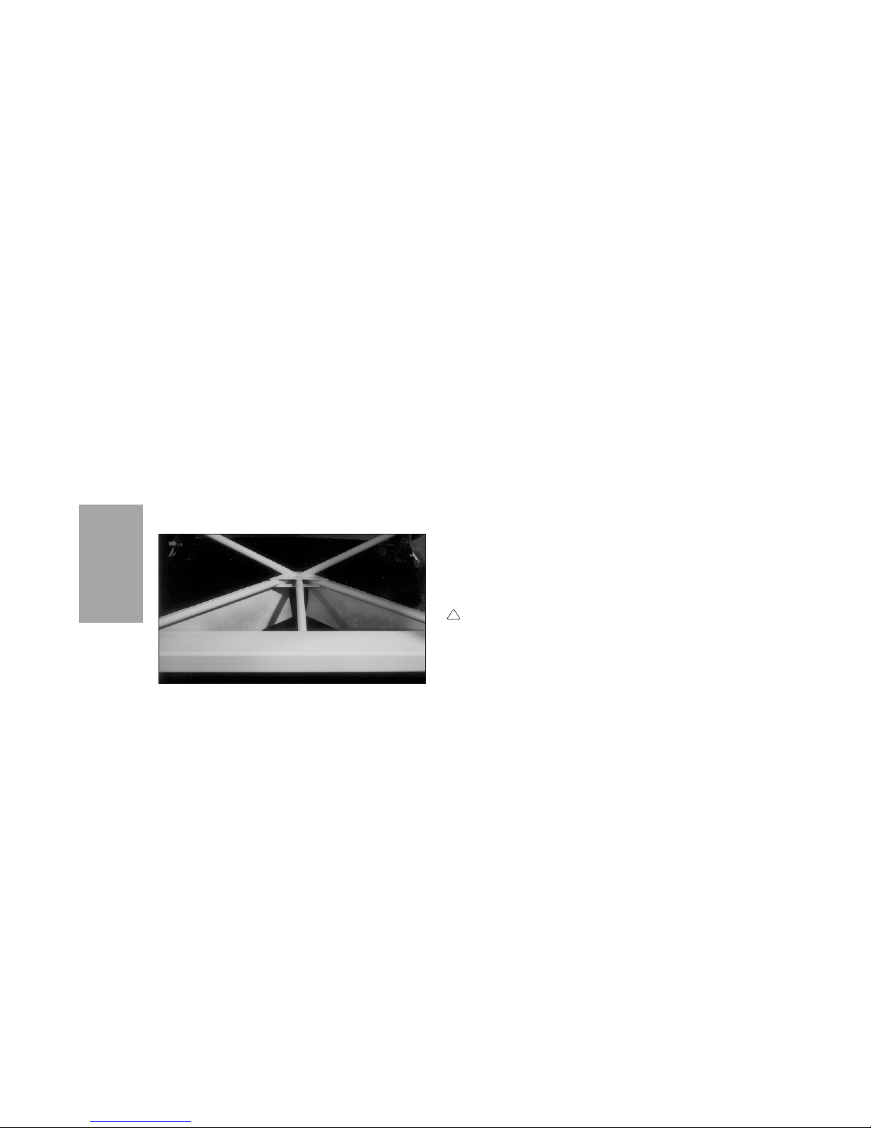
On Pelicans equipped with dual side brooms there
are two dirt deflectors (Figure SP-14) mounted in
the center of the unit. These dual dirt deflectors
form a “V” under the hopper area.
On single broom units a dirt deflector is located on
the left hand side just ahead of the dirt shoe. A rubber runner maintains contact with the street to
prevent debris from being thrown to the side
beyond the reach of the main broom. This runner
may be adjusted by loosening the nuts in the metal
plate and raising or lowering the runner as needed.
All dirt deflectors should be inspected regularly and
changed if damaged or worn.
CONVEYOR
CONVEYOR ACCESS
The hopper must be rolled out and lowered to provide safe access to the conveyor. To perform the
safety roll-out, use the following procedure.
DANGER
Raise or dump hopper in areas free of power
lines. Before raising or tilting hopper, check
for adequate overhead and forward clearance.
Raise hopper only in areas with minimum
overhead clearance of 16 ft (5 m) and forward
clearance of 3 ft (1 m). Do not raise hopper
while under trees, bridges, etc.
!
SERVICE
PROCEDURES
SP-16
Dirt Deflectors on Dual Unit
Figure SP-14
Page 83
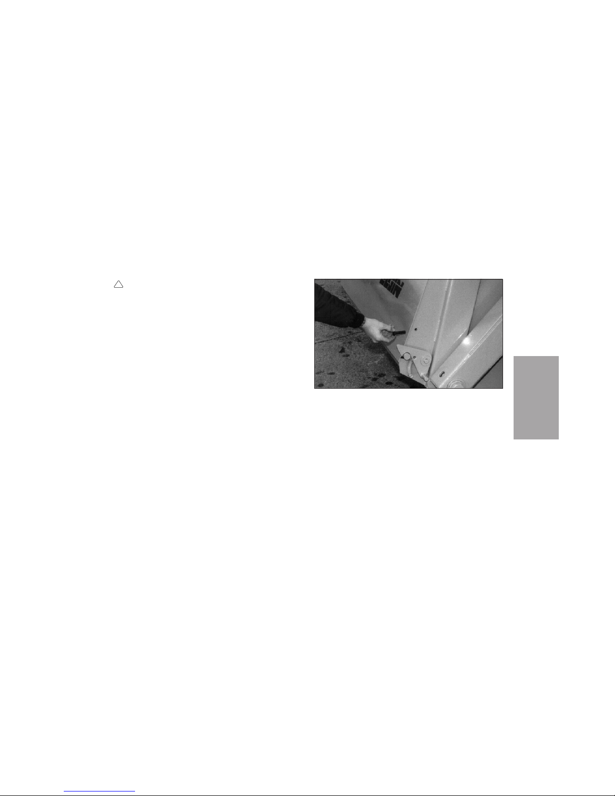
WARNING
DO NOT work under or around a raised hopper. The best method for safe access to the
machine behind the hopper is the roll-out
method described below.
1. Install a 1/2 x 2 1/2-inch bolt in each of the two
holes located above the spring-loaded door
latches on the sides of the hopper (Figure
SP-15). The bolts will hold the hopper door
closed during roll-out.
2. Raise the hopper slightly and begin to tilt
("roll") the hopper completely over, raising and
tilting the hopper as needed.
3. When the hopper reaches the limit of its
motion, carefully lower the hopper completely
to the surface on which the sweeper is standing (Figure SP-16).
!
SP-17
SERVICE
PROCEDURES
Locking Hopper Door For Rollout
Figure SP-15
Page 84
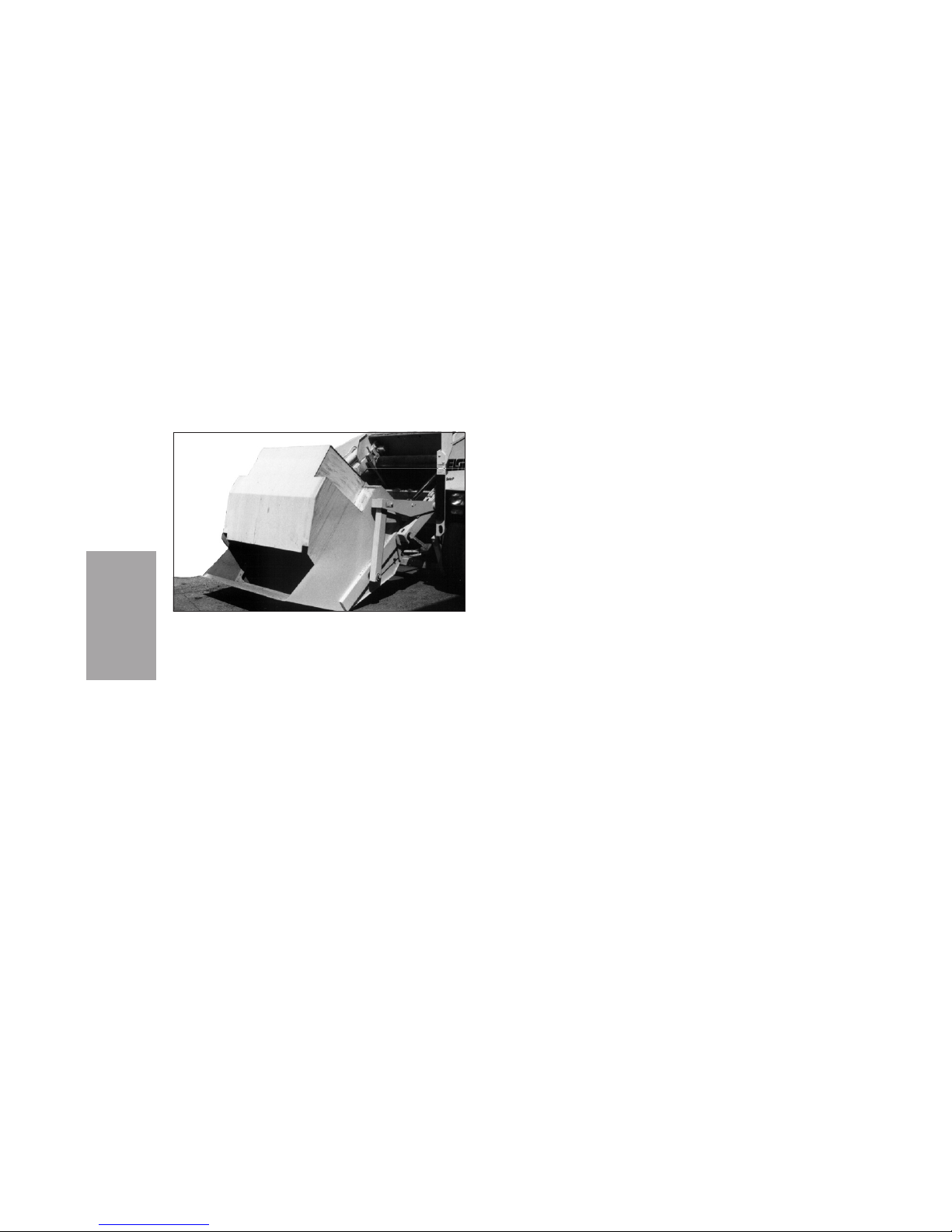
ADJUSTING CONVEYOR
Conveyor Belt Adjustments
Before belt adjustment, the conveyor belt must be
clean and the lower roll area must be flushed out.
The main broom and conveyor must be lowered.
NOTICE
Do not attempt to adjust the conveyor belt with the
conveyor system in the raised position.
Proper conveyor belt adjustment involves first setting tension and then adjusting alignment by the
procedures under Belt Tension and Belt Alignment.
NOTICE
Belt tension and alignment for both rolls are interrelated. During tension adjustment, the belt must be
kept nearly centered, but tension must be correct
before final adjustment of alignment. It is important to make small adjustments and to check belt
tension and alignment by operating the belt for at
least 30 minutes between adjustments.
A properly tensioned belt will have good clearance
between each belt cleat and the lower conveyor
backing plate. Too much slack will cause "flapping"
of the belt against the backing plate and result in
damage to the belt.
The conveyor belt must be accurately aligned, or
trained, to stay on the middle of the rollers. A misaligned belt can travel across the rollers and into
SERVICE
PROCEDURES
SP-18
Hopper Rolled Out For Service
Figure SP-16
Page 85

the conveyor sides, where it will suffer tearing or
other damage.
BELT TENSION
The conveyor belt has correct tension when there is
clearance between the tip of any cleat and conveyor
backing plate. If too loose, the belt may slip on the
upper roll and the cleats may show wear from dragging over the backing plate. DO NOT overtighten
belt, as this will cause premature failure.
To adjust belt tension, use the following procedure.
WARNING
DO NOT work under or around a raised hopper.
1. After following the procedure under Conveyor
Access, lower the main broom, conveyor, and
side broom.
WARNING
Contact with moving parts can cause severe
injury. Do not attempt repairs or go under-
neath machine with engine running. Use
extreme care when making checks or adjustments that require the engine to be running.
NOTICE
All belt tension adjustments should be made with
no more than one-half turn of the adjusting nuts
at any one time. The conveyor should then be run at
least 30 minutes to check the results before making
another adjustment.
2. Loosen the jam nuts on each side of the upper
conveyor assembly (Figure SP-17).
3. As needed to achieve correct tension that is
uniform across the belt, turn both adjusting
nuts. Turn the nuts clockwise to increase tension or counterclockwise to decrease tension.
Turn each nut only one-half turn at a time.
4. With the engine running at about 1200 RPM,
operate the conveyor for at least 30 minutes
between adjustments to check belt tension,
alignment, and direction of travel, if any, over
both the upper and lower rolls.
!
!
SP-19
SERVICE
PROCEDURES
Page 86
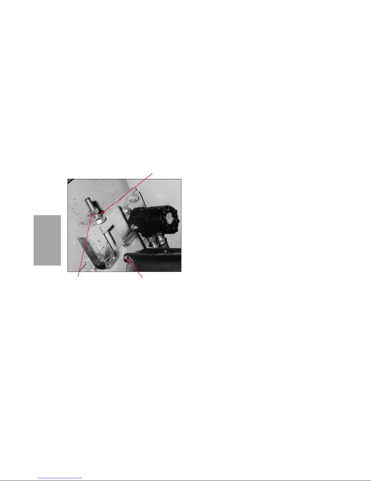
5. If the belt "flaps" against the lower conveyor
cover, increase overall belt tension by continuing adjustment steps on both sides of the
upper conveyor roll.
6. If alignment does not need adjusting, tighten
the jam nuts.
BELT ALIGNMENT
Proper belt alignment will require making small
adjustments to the upper roll as outlined below. As
a result, upper conveyor roll take-ups may not have
equal final adjustments.
In some cases, adjusting the upper roll may not be
sufficient to keep the belt centered on both rolls. It
may be necessary to make similar adjustments to
the lower roll.
NOTICE
Belt tension, alignment, and centering adjustments
SERVICE
PROCEDURES
SP-20
JAM NUT UPPER ROLL GREASE FITTING
Upper End Of Conveyor Assembly
Figure SP-17
ADJUSTING NUT
Page 87

for both rolls are interrelated. While adjusting
alignment, it is important to make small adjustments and to maintain proper tension.
Reference to right or left side of the sweeper is relative to the operator's position in the driver's seat.
WARNING
DO NOT work under or around a raised hopper.
Before beginning belt alignment, follow the procedure under Conveyor Access.
Follow these guidelines for correct belt alignment:
Adjust the conveyor to give correct belt tension
before making final adjustments in alignment.
Operate the conveyor long enough to bring the belt
up to steady operating temperature, before trying
to completely adjust alignment.
............................BELT TRAVELS TO THE RIGHT
Increasing tension on the right side or decreasing
tension on the left will draw the belt to the left.
BELT TRAVELS TO THE LEFT.............................
Increasing tension on the left side or decreasing
tension on the right will draw the belt to the right.
Operate the conveyor for at least 30 minutes
between adjustments.
NOTICE
Do not operate conveyor in reverse for more than 30
seconds without allowing forward motion to center
belt. Excessive reverse running can damage belt.
When the belt seems to be properly centered, test
the stability of the alignment by operating the conveyor in reverse for about 15 seconds and then running it forward. Within about 5 minutes, a correctly
adjusted conveyor will center the belt and keep it
centered.
!
SP-21
SERVICE
PROCEDURES
Page 88
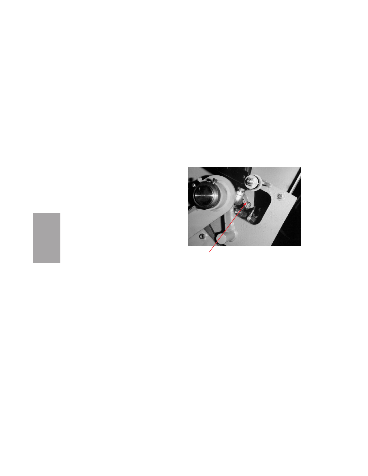
Other Conveyor Adjustments
LOWER ROLL SCRAPER
ADJUSTMENT
Lower roll scraper adjustment should be checked
periodically and whenever the belt is removed. The
square opening just above the lower roll bearing
(Figure SP-18) provides access for adjustment. To
adjust the scraper, take the following steps.
1. Loosen two nuts at each end of the scraper.
2. Adjust the scraper to clear the roll by no more
than 1/16 inch (1.6 mm).
3. Tighten the nuts.
NOTICE
The condition of the lower belt scraper (rubber) that
is part of the lower roll scraper assembly should be
checked, and the belt scraper should be replaced, if
necessary.
SERVICE
PROCEDURES
SP-22
ROLL SCRAPER
Right Side Of Lower Roll
Figure SP-18
Page 89
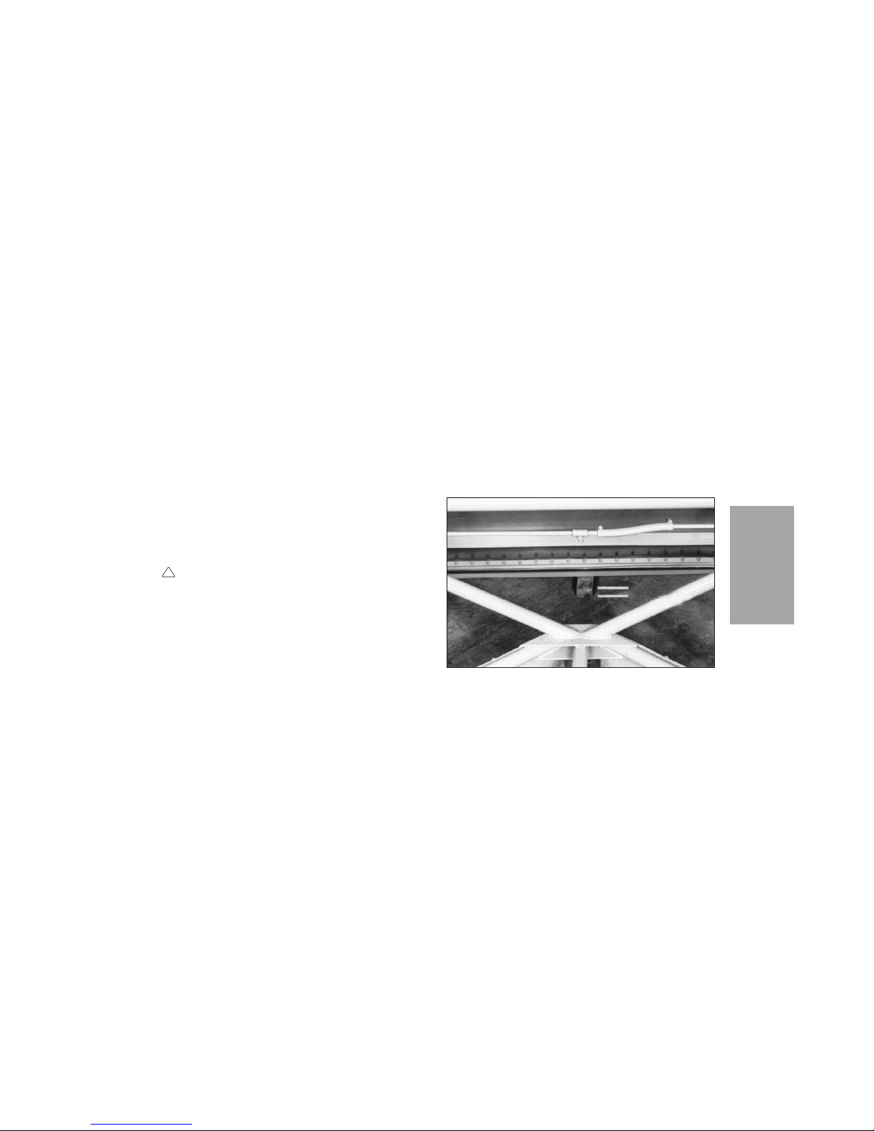
CONVEYOR GROUND CLEARANCE
Conveyor ground clearance (height) should be
adjusted after the new belt is in place to ensure
good conveyor performance. The clearance may be
out of adjustment for a machine in the field due to
wear and loosening of the lower roll bearings and
conveyor lift cylinders.
1. Park the sweeper on a level surface.
2. Remove the main broom.
WARNING
DO NOT work under or around a raised hopper.
3. Follow the procedure under Conveyor Access.
4. Lower the conveyor.
5. Rotate the conveyor belt by hand until one belt
cleat is perpendicular to the surface on which
the sweeper is standing.
6. Place a 1-5/8 ± 1/4 inch (41 ± 6 mm) wooden
block under the cleat at the middle of the conveyor belt (Figure SP-19). (A standard 2 x 4
block can be used to estimate this dimension.)
The cleat should touch or barely clear the
block.
!
SP-23
SERVICE
PROCEDURES
Ground Clearance Of Conveyor
Figure SP-19
Page 90
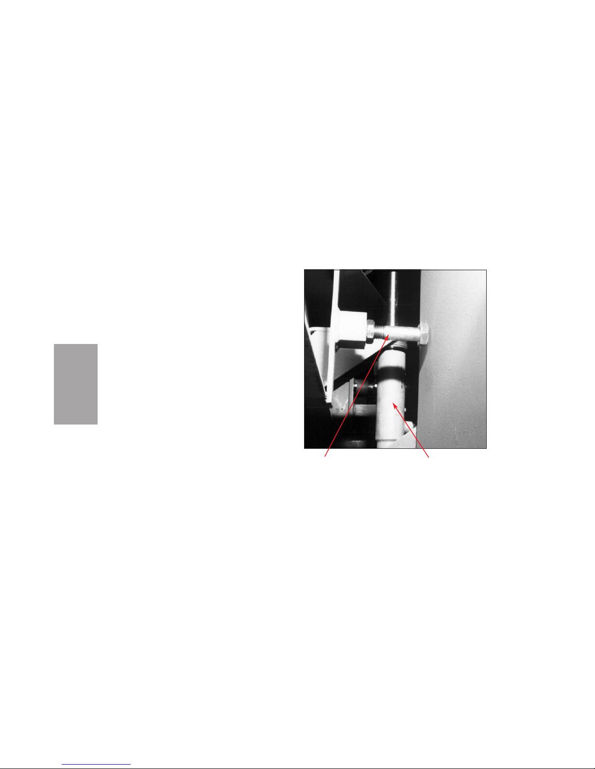
NOTICE
Due to the lower roll offset, clearance at the left side
will be slightly less than the clearance at the middle, and clearance at the right side will be greater.
7. If adjustment is necessary, take the following
steps.
a. Raise the conveyor.
b. Block and support the conveyor.
c. With the pistons of the conveyor lift cylin-
ders (Figure SP-20) retracted, remove the
snap ring at the bottom of each cylinder,
and remove both cylinders.
d. Add or remove an equal number of shim
washers at the rod end of each cylinder. An
equal number is used to maintain conveyor
squareness.
e. Install the cylinders and snap rings.
f. Unblock and lower the conveyor.
g. Repeat the clearance checking procedure.
SERVICE
PROCEDURES
SP-24
STOP BOLT LIFT CYLINDER
Left Side Of Conveyor
Figure SP-20
Page 91
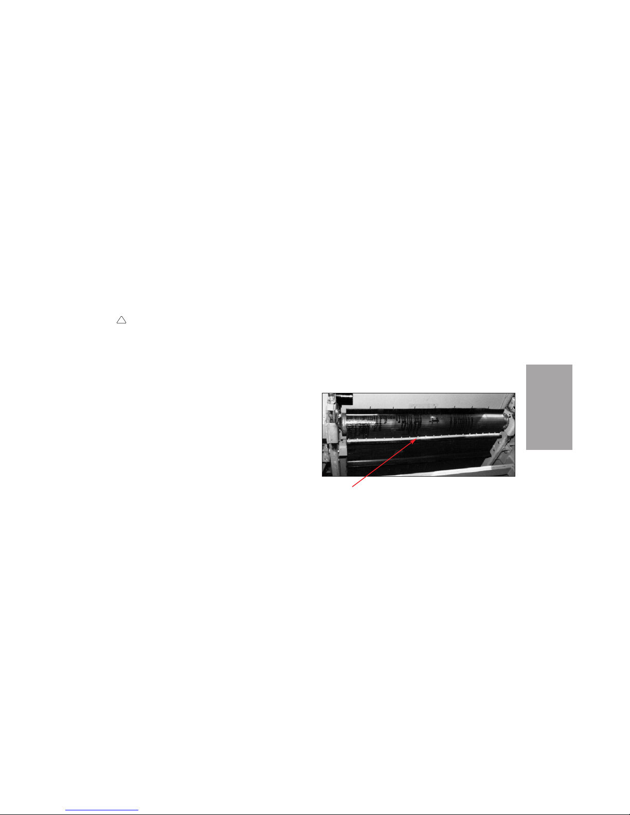
REPLACING CONVEYOR BELT
WARNING
DO NOT work under or around a raised hopper.
In preparation for replacement of the conveyor belt,
the sweeper must be parked on a flat, level
surface.
Before beginning replacement of the belt,
follow the procedure under Conveyor Access.
Removing Conveyor Belt
Before the conveyor belt is removed or installed,
the main broom must be removed by the procedure
under Main Broom Replacement.
With the main broom removed, use the following
procedure to remove the belt..
1. Raise the conveyor to transport position.
2. Rotate the conveyor belt to expose the belt
splice at the upper conveyor roll area (Figure
SP-21).
3. Loosen the jam nuts and back them off the
adjusting nuts on both sides of the conveyor
(Figure SP-17).
4. Turn the adjusting nuts to reduce overall belt
tension on both sides of the belt.
!
SP-25
SERVICE
PROCEDURES
SPLICE
Conveyor Belt
Figure SP-21
Page 92

5. Disassemble the belt splice and allow the belt
to fall beneath the sweeper.
6. Remove the belt from under the sweeper.
Squaring Conveyor Structure
The conveyor structure should be checked and
adjusted for squareness in the sweeper and to the
sweeping surface. Use the following procedure.
1. On the conveyor structure, select a reference
point (e.g., a bolt or bracket) that is common to
both sides.
2. Measure the distance from each reference
point to the surface on which the sweeper is
standing.
3. If the two measurements do not closely match,
square the conveyor structure by taking the
following steps.
a. Raise the conveyor.
b. Block and support the conveyor.
c. With the pistons of the conveyor lift cylin-
ders (Figure SP-20) retracted, remove the
snap ring at the bottom of the appropriate
cylinder, and remove the cylinder.
d. Add one or more shim washers at the rod
end of the cylinder.
e. Install the cylinder and snap ring.
f. Unblock and lower the conveyor.
g. Repeat the measurement procedure and, if
necessary, repeat the adjustment procedure
until the conveyor structure is squared.
NOTICE
To achieve squareness, the number of washers on
the two cylinders will generally be different. When
ground clearance is adjusted, this difference should
be maintained throughout the adjustment. See
CONVEYOR GROUND CLEARANCE.
SERVICE
PROCEDURES
SP-26
Page 93

Structure Stop Bolt Adjustment
Above the conveyor lift cylinders, there are two stop
bolts (Figure SP-20) that guide the conveyor in tow
through U-turns and sweeping, preventing damage
to the conveyor and other components under the
sweeper. There should be a 1/8-inch (3 mm) gap
between these bolts and the sweeper side plates.
The bolts should not ride against the side plates.
Lower Roll Offset Adjustment
Lower roll offset is needed to compensate belt tension for the material "loading" effect that occurs on
the right side of the conveyor during standard
right-hand sweeping.
The offset is adjusted at the factory and normally
needs little or no readjustment, but it should be
checked with every new belt installation. Offset
may be out of adjustment for a machine in the field
due to wear and loosening of the lower roll bearings
and conveyor lift cylinders. Adjusting the offset can
make conveyor belt installation easier or help solve
alignment ("training") difficulties. See CONVEYOR
BELT ADJUSTMENT.
NOTICE
Reference to right- or left-hand in the following procedure is based on the operator's seated position facing forward in the sweeper.
1. With the belt removed or belt tension released,
check the left-hand lower roll bearing (Figure
SP-22). The lower edge of the bearing casting
should be flush with the end of the conveyor
weldment. If necessary, adjust the position of
the bearing.
2. Check the right-hand lower roll bearing
(Figure SP-23). The lower edge of the bearing
casting should be approximately one-half inch
(13 mm) up from the end of the conveyor weldment.
SP-27
SERVICE
PROCEDURES
Page 94
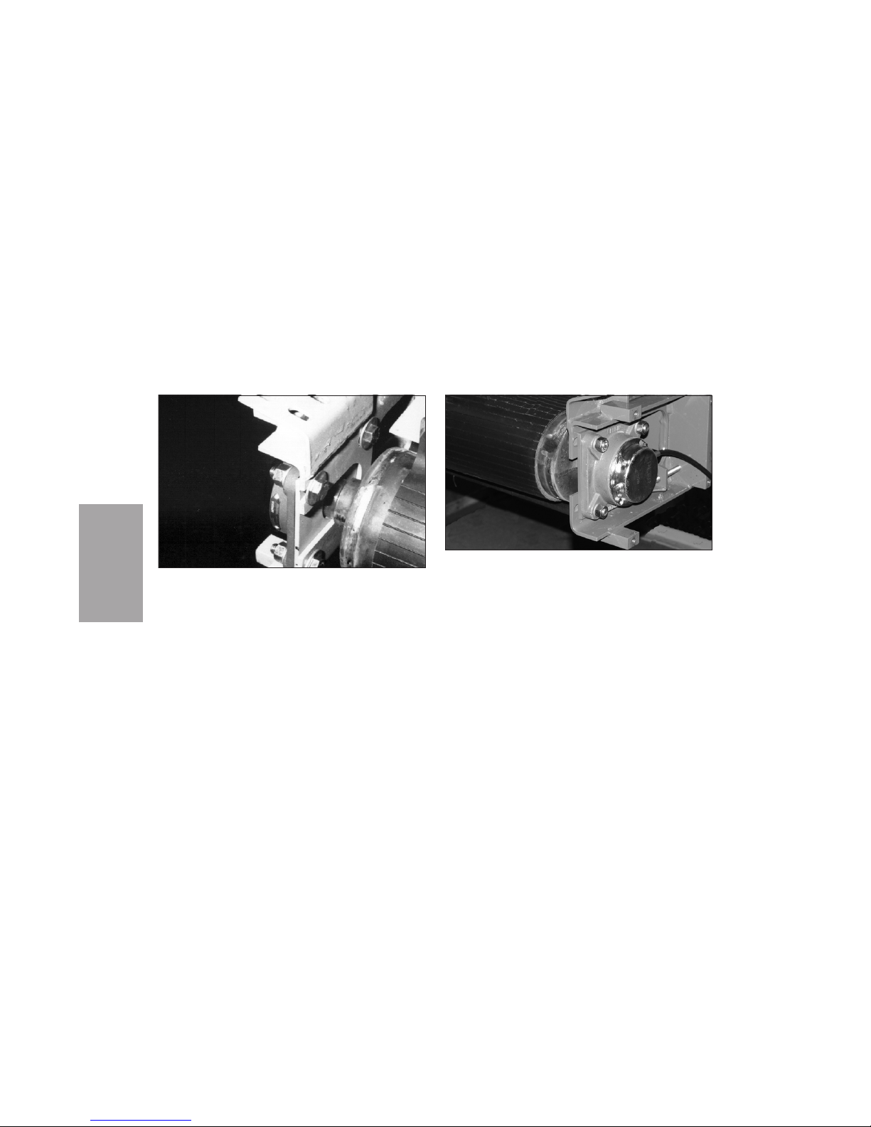
NOTICE
These settings may require slight readjustment, similar to adjustment of the upper roll, during belt tensioning and alignment. See CONVEYOR BELT
ADJUSTMENT.
Installing Conveyor Belt
NOTICE
If the lower roll offset is properly adjusted before a
new belt is installed, belt adjustment is easier.
Proper offset can also help solve problems of alignment (“training”) with a belt that has been in use.
See Lower Roll Offset Adjustment.
SERVICE
PROCEDURES
SP-28
Left Hand Lower Roll Bearing
Figure SP-22
Figure SP-23
Right-Hand Lower Roll Bearing
Page 95
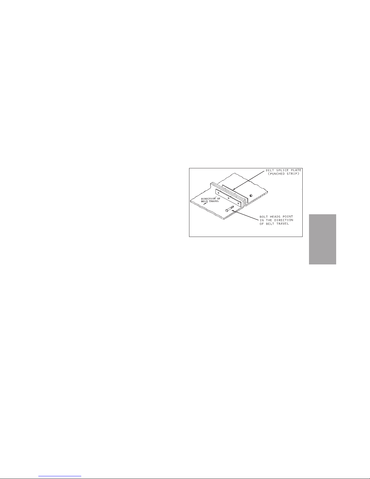
To install a conveyor belt, use the following
procedure.
1. Lower one end of the conveyer belt (cleats out)
past the upper roll and down through the
underside of the conveyor to the lower roll.
2. Loop the other end of the belt over the upper
roll and feed it downward.
3. Position the entire belt as close to the center of
each roller as possible. The belt edges should
run parallel to the conveyor belt guide plates.
4. From a position under the machine at the
lower roll, gather both ends of the belt, and
install the belt splice as if you were closing a
zipper (Figure SP-24).
NOTICE
Mounting bolt heads in the splice should face the
direction of normal belt travel.
SPLICING CONVEYOR BELT
To remove a conveyor belt for repair or to install a
repaired belt, see the precautions and instructions
under Replacing Conveyor Belt.
SP-29
SERVICE
PROCEDURES
Belt Splice Installation
Figure SP-24
Page 96

A torn or damaged belt may be repaired in the field
by cutting out the damaged part with a squared cut
across the whole width of the belt and inserting a
new section also squared off to match the length of
the part removed (Figure SP-25). This requires two
splices, one at each end of the new belt section
added. Should damage occur near the original
splice, the new section may be added at the end
and only one splice need be added.
REVERSING CONVEYOR
The conveyor assembly and belt adjustments are
designed to train the belt in forward (sweeping)
motion only. The reversing feature is only for the
purpose of relieving any condition which has
caused a jamming effect of the belt or driving mechanism and normally will not be prolonged over a
period of 30 seconds. Longer periods of time may
cause the belt to run either to the extreme right or
left, causing damage to the belt.
NOTICE
Do not operate conveyor in reverse for more than 30
seconds without allowing forward motion to center
belt. Excessive reverse running can damage
conveyor belt.
SERVICE
PROCEDURES
SP-30
Page 97
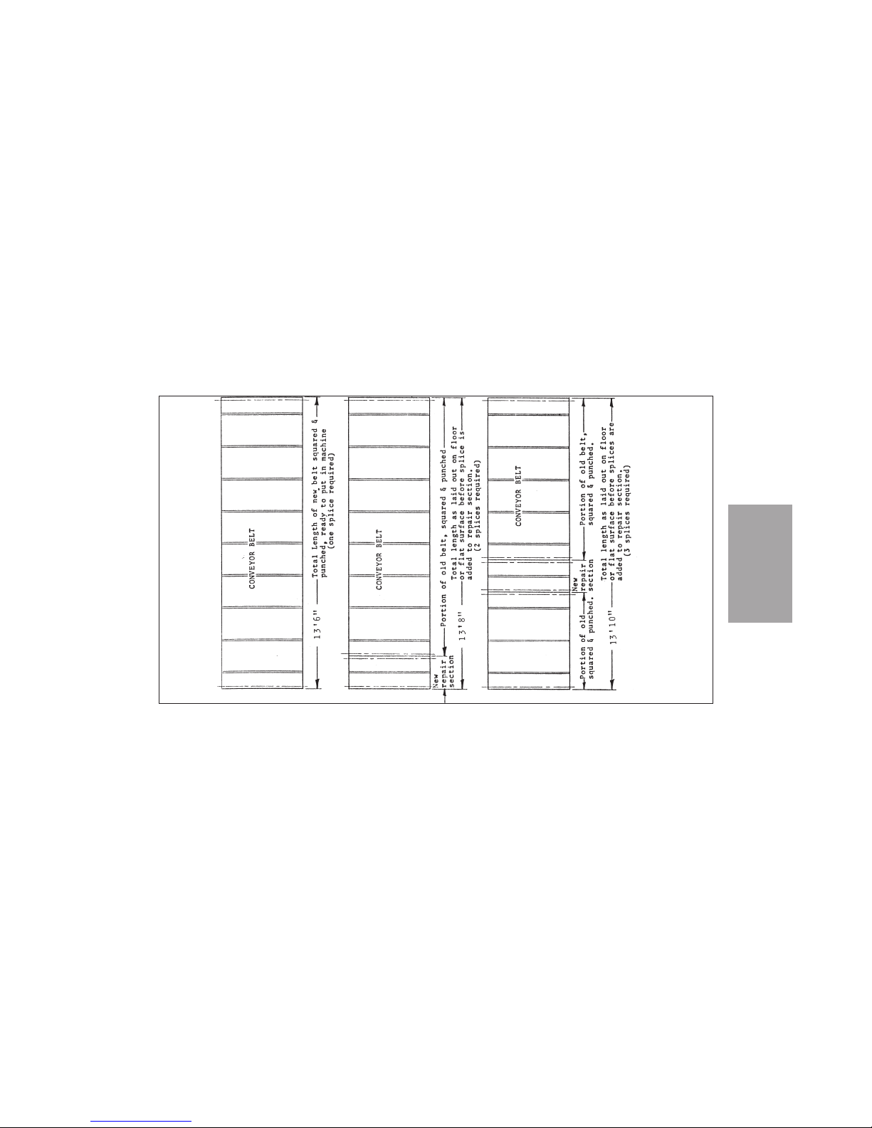
SP-31
SERVICE
PROCEDURES
Belt Repairs
Figure SP-25
Page 98
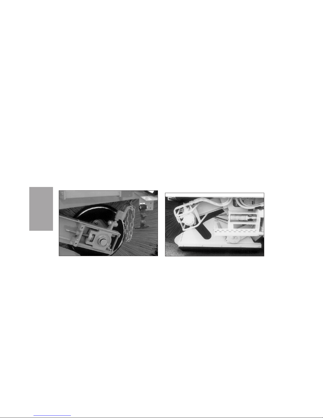
MAIN BROOM REPLACEMENT
To prepare for the removal of the main broom on a
Pelican with standard (chain) broom suspen-
sion (Figure SP-26), raise the main broom and
release the suspension chains on both sides of the
machine.
To prepare for removal of the main broom on a
Pelican with hydraulic broom suspension
(Figure SP-27), lower the broom to just touch the
ground. This will properly balance and suspend
the main broom, making disassembly of the lefthand lower broom arm easier. (If the broom goes
down too far, raise it all the way up and lower it
again.)
SERVICE
PROCEDURES
SP-32
Main Broom Chain Suspension
Figure SP-26
Hydraulic Main Broom Suspension
Figure SP-27
Page 99

Then follow this procedure:
1. Turn the steering wheel all the way to the left.
This will allow room to handle the main broom.
WARNING
Contact with rotating main broom can cause
personal injury or property damage. Turn
broom(s) and engine off before inspecting or
servicing broom.
2. Shut down the engine.
3. Remove the three main broom drive hub
mounting bolts from the broom core on the
right side of the machine.
4. Remove the main broom lower arm mounting
bolts from the left-hand upper main broom
arm.
5. Pull the main broom (with lower arm attached)
out from under the left side of the sweeper and
set aside.
6. Remove the main broom from the lower arm.
7. Install a new main broom on the lower arm.
8. Place the new main broom and lower arm
under the left side of the sweeper.
9. Install the main broom lower arm mounting
bolts on the left upper main broom arm.
!
SP-33
SERVICE
PROCEDURES
Page 100

10. Install the three main broom drive hub mounting bolts on the broom core on the right side of
the machine.
CAB AIR FILTER
Clean air for the heater, air conditioner and cab
pressurizer is drawn through a filter. This filter
should be checked and replaced on a regular basis.
The exact frequency will depend on operating conditions.
WHEELS AND TIRES
Jack pads are provided behind the front drive
wheels on both sides of the Pelican. A bottle jack
can be used with these jack pads to lift the front of
the sweeper for tire changing.
NOTICE
Do not use the chassis of the sweeper when jacking
it up. Always use the jack pads.
To change a rear guide wheel, use a small bottle
jack between the two guide wheel tires to lift the
sweeper.
NOTICE
Always use matching tires on the guide wheel. Use
of non-matching tires may result in uneven wear or
cause one tire to carry the entire weight.
WINTER STORAGE
To prepare the sweeper for seasonal or other longterm storage, take the following steps.
1. Empty the hopper and thoroughly wash down
the sweeper.
2. Fill the fuel tank to minimize condensation of
moisture.
CAUTION
Battery gas can explode. Keep sparks and
flames away from batteries. If the battery electrolyte level must be checked, use an electric
!
SERVICE
PROCEDURES
SP-34
 Loading...