

Page 1

Copyright © 2012, 2010 by Elenco®Electronics, Inc., all rights reserved. No part of this book shall be reproduced by 753292
any means; electronic, photocopying, or otherwise without written permission from the publisher.
REV-E Revised 2012
Project 526
Page 2
-1-
Table of Contents
Basic T roubleshooting 1
Parts List 2
About the Two-Spring Socket (?1) 3
MORE
About Your Snap Circuits®Parts 4
MORE
Advanced T roub leshooting 4
MORE
DO’s and DON’Ts of Building Circuits 5
Project Listings 6, 7
Projects 512-692 8 - 84
Other Fun Elenco®Products 85 - 86
1. Most circuit problems are due to incorrect assembly.
Always double-check that your circuit exactly
matches the drawing for it.
2. Be sure that parts with positive/negative markings are
positioned as per the drawing.
3. Be sure that all connections are securely snapped.
4. Try replacing the batteries.
5. If the motor spins but does not balance the fan, check
the black plastic piece with three prongs on the motor
shaft. Be sure that it is at the top of the shaft.
Elenco
®
is not responsible for parts damaged due to
incorrect wiring.
Basic T roub leshooting
Note: If you suspect you have damaged parts, you can
follow the Advanced Troubleshooting procedure on page 4
to determine which ones need replacing.
Review of How To Use It (See page 3 of the Projects 1-101 manual for more details.)
The Snap Circuits®kit uses building blocks with snaps
to build the different electrical and electronic circuits in
the projects. These blocks are in different colors and
have numbers on them so that you can easily identify
them. The circuit you will build is shown in color and
with numbers, identifying the blocks that you will use
and snap together to form a circuit.
Next to each part in every circuit drawing is a small
number in black. This tells you which level the
component is placed at. Place all parts on level 1 first,
then all of the parts on level 2, then all of the parts on
level 3, etc.
A large clear plastic base grid is included with this kit
to help keep the circuit block together. The base has
rows labeled A-G and columns labeled 1-10.
Install two (2) “AA” batteries (not included) in the
battery holder (B1). The 2.5V and 6V bulbs come
packaged separate from their sockets. Install the 2.5V
bulb in the L1 lamp socket, and the 6V bulb in the L2
lamp socket.
Place the fan on the motor (M1) whenever that part is
used, unless the project you are building says not to
use it.
Some circuits use the red and black jumper wires to
make unusual connections. Just clip them to the metal
snaps or as indicated.
Note: While building the projects, be careful not to
accidentally make a direct connection across the
battery holder (a “short circuit”), as this may damage
and/or quickly drain the batteries.
WARNING: SHOCK HAZARD -
Never connect Snap Circuits®to
the electrical outlets in your home
in any way!
WARNING FOR ALL PROJECTS WITH A SYMBOL
Moving parts. Do not touch the motor or fan during operation. Do not lean
over the motor. Do not launch the fan at people, animals, or objects. Eye
protection is recommended.
!
!
WARNING: CHOKING HAZARD-
Small parts.
Not for children under 3 years.
!
Batteries:
• Use only 1.5V AA type, alkaline batteries
(not included).
• Insert batteries with correct polarity.
• Non-rechargeable batteries should not
be recharged. Rechargeable batteries
should only be charged under adult
supervision, and should not be
recharged while in the product.
• Do not mix alkaline, standard (carbonzinc), or rechargeable (nickel-cadmium)
batteries.
• Do not mix old and new batteries.
• Remove batteries when they are used up.
• Do not short circuit the battery terminals.
• Never throw batteries in a fire or attempt
to open its outer casing.
• Batteries are harmful if swallowed, so
keep away from small children.
• Do not connect batteries or battery
holders in parallel.
!
WARNING: Always check your wiring before
turning on a circuit. Never leave a circuit
unattended while the batteries are installed. Never
connect additional batteries or any other power
sources to your circuits. Discard any cracked or
broken parts.
Adult Supervision: Because children’s abilities
v
ary so much, even with age groups, adults should
exercise discretion as to which experiments are
suitable and safe (the instructions should enable
supervising adults to establish the experiment’s
suitability for the child). Make sure your child reads
and follows all of the relevant instructions and
safety procedures, and keeps them at hand for
reference.
This product is intended for use by adults and
children who have attained sufficient maturity to
read and follow directions and warnings.
Never modify your parts, as doing so may disable
important safety features in them, and could put
your child at risk of injury.
!
Page 3
-2-
Note: There are additional part lists in your other project manuals. Part designs are subject to change without notice.
Important: If any parts are missing or damaged, DO NOT RETURN TO RETAILER. Call toll-free (800) 533-2441 or e-mail us at:
help@elenco.com. Customer Ser vice • 150 Car penter Ave. • Wheeling, IL 60090 U.S.A.
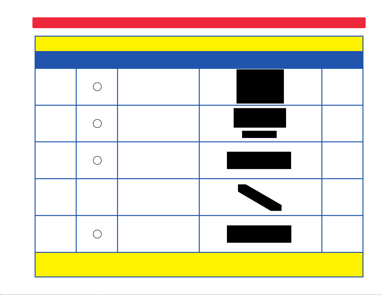
Parts List (Colors and styles may vary) Symbols and Numbers
Qty. ID Name Symbol Par t #
r 1
Solar Cell 6SCB2
r 1
r 1
Electromagnet
Iron Core Rod
6SCM3
6SCM3B
r 1
Vibration Switch 6SCS4
r 1
Bag of Paperclips 6SCM3P
r 1
Two-spring
Socket
6SCPY1
You may order additional / replacement parts at our website: www.snapcircuits.net
?1
S4
M3
B2
Page 4
-3-
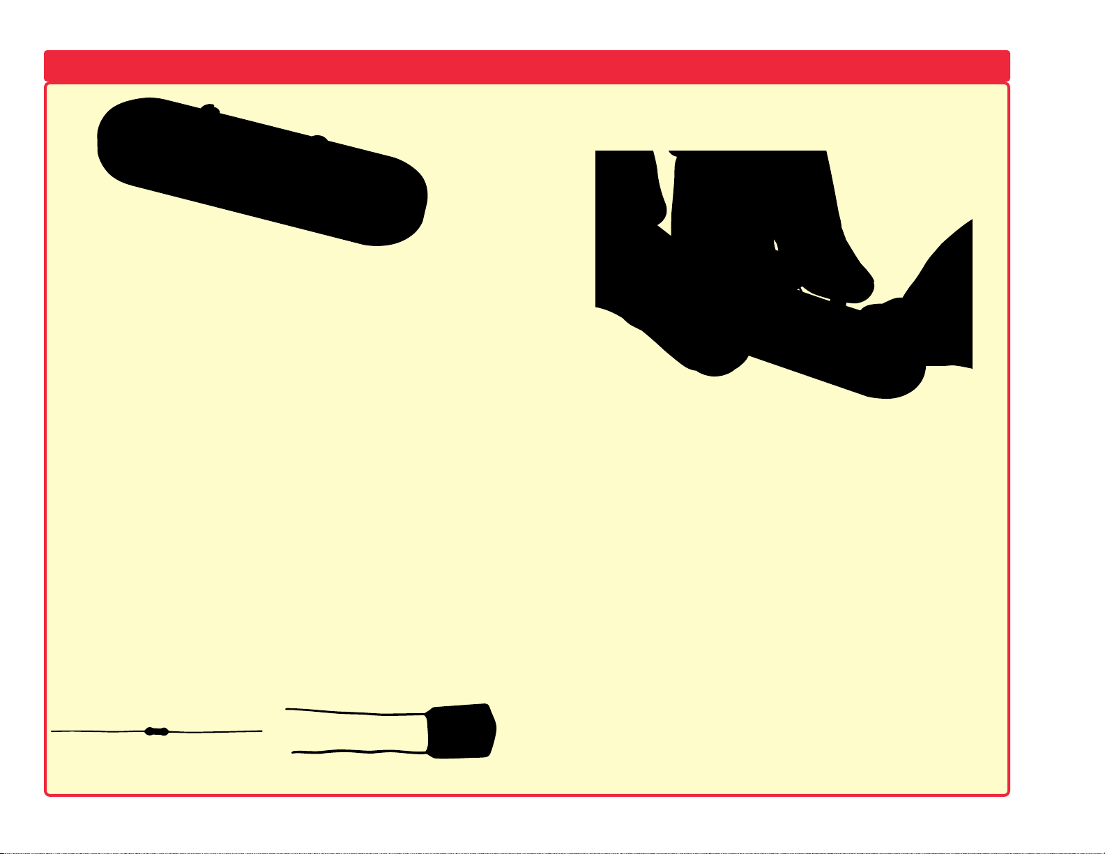
The two-spring socket (?1) just has two springs, and won’t do
anything by itself. It is not used in any of the experiments. It was
included to make it easy to connect other electronic components to
your Snap Circuits
®
. It should only be used b y adv anced users who
are creating their own circuits.
There are many different types of electronic components and basic
parts like resistors and capacitors have a wide range of available
values. For example, Snap Circuits
®
includes five fixed-value
resistors (100Ω, 1KΩ, 5.1KΩ, 10KΩ, and 100KΩ). This is a very
limited choice of values, and difficult to design circuits with. Snap
Circuits
®
also includes a adjustable resistor (RV), but it is difficult to
set this part to a par ticular value. You can place your resistors in
series and parallel to make different values (as is done with the
5.1KΩ and 10KΩ in project #166), but this is also difficult with only
five values to choose from.
Many customers like to create their own circuits and asked us to
include more resistor values with Snap Circuits
®
. We could have
done that, but you would never hav e enough. And resistors are not
very exciting components by themselv es. You could try to use your
own resistors, but they are difficult to connect since normal
electronic parts come with wires on them instead of snaps.
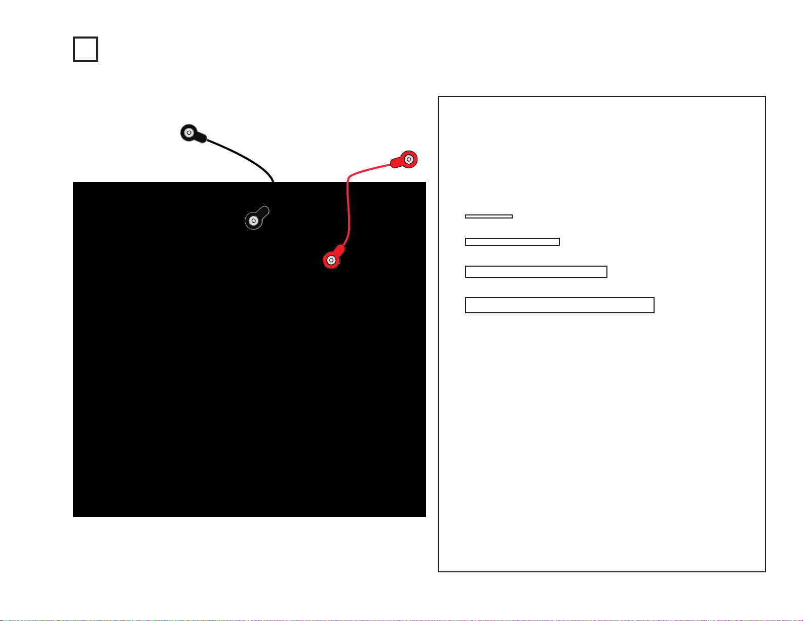
The two-spring socket (?1) makes it easy to connect your own
resistors (and other parts) to circuits by connecting them between
the springs:
Any component with two wires coming from it (called leads) can be
connected with the two-spring socket (?1), assuming the leads are
long enough. Usually you will connect different values of resistors
or capacitors, but other components like LED’s, diodes, or
coils/inductors can also be used. You can usually find electronic
components at any store specializing in electronics.
You can design your own circuits or substitute new parts into the
projects in the manuals. For LED’s, diodes, or electrolytic
capacitors, be sure to connect your parts using the correct polarity
or you may damage them. Never exceed the v oltage r atings of an y
parts. Never connect to external voltage sources. ELENCO
®
IS
NOT RESPONSIBLE FOR ANY PARTS DAMAGED BY
IMPROPER CIRCUIT DESIGN OR WIRING. The two-spring
socket is only intended for advanced users.
About the TWO-SPRING SOCKET (?1)
Resistor Capacitor
To learn more about how circuits work, visit www.snapcircuits.net or page 85 to find out about our Student Guides.
Page 5
Elenco®is not responsible for parts damaged due to incorrect wiring.
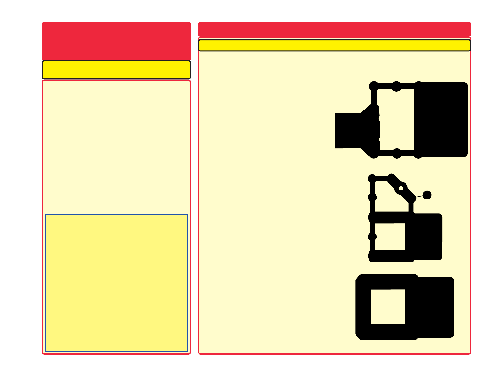
If you suspect you have damaged parts, you can follow this procedure to systematically
determine which ones need replacing:
1 - 28. Refer to the other project manuals for testing steps 1-28, then continue below.
29. Solar Cell (B2): Build the mini-circuit shown
here and set the meter (M2) to the LO
W (or
10mA) setting. Hold the circuit near a lamp
and the meter pointer should move.
30. Electromagnet (M3): Build the mini-circuit
sho
wn here. Lamp (L1) must be dim, and must
get brighter when you press the press switch
(S2).
31. Vibration Switch (S4): Build the mini-circuit
sho
wn here and shake the base grid. The LED
should go on and off as you shake.
-4-
The solar cell (B2) contains positively and negatively
charged silicon crystals, arranged in layers that cancel
each other out. When sunlight shines on it, charged
particles in the light unbalance the silicon layers and
produce an electrical voltage (about 3V). The maximum
current depends on how the type of light and its
brightness, but will be much less than a battery can
supply. Bright sunlight works best, but incandescent light
bulbs also work.
The electromagnet (M3) is a large coil of wire, which acts
lik
e a magnet when a current flows through it. Placing an
iron bar inside increases the magnetic effects. Note that
magnets can erase magnetic media like floppy discs.
When shaken, the vibraton switch (S4) contains two
separ
ate contacts; and a spring is connected to one of
them. A vibration causes the spring to move, briefly
connecting the two contacts.
The two-spring socket (?1) is described on page 3.
MORE
Advanced T roubleshooting (Adult supervision recommended)
MORE
About Y our
Snap Circuits®Parts
(Note: There is additional information in your other project manuals).
A Note on Sun Power
The sun produces heat and light on an immense scale, by
transforming Hydrogen gas into Helium gas. This
“transformation” is a thermonuclear reaction, similar to the
explosion of a Hydrogen bomb. The earth is protected from
most of this heat and radiation by being so far a w ay, and by
its atmosphere. But e v en here the sun still has power, since
it can spin the motor on your kit and give you sunburn on a
hot day.
Nearly all of the energy in any form on the surface of the
earth originally came from the sun. Plants get energy for
growth from the sun using a process called photosynthesis.
People and animals get energy for growth by eating plants
(and other animals). Fossil fuels such as oil and coal that
power most of our society are the decayed remains of
plants from long ago. These fuels exist in large but limited
quantity, and are rapidly being consumed. Solar cells will
produce electricity as long as the sun is bright, and will
have an ever-increasing effect on our lives.
Our Student Guides give much more information about your
parts, along with a complete lesson in basic electronics. See
www.snapcircuits.net/learn.htm for more information.
Page 6

-5-
MORE
DO’s and DON’Ts of Building Circuits
After building the circuits given in this booklet, you may wish to experiment on your
own. Use the projects in this booklet as a guide, as many important design concepts
are introduced throughout them. Every circuit will include a power source (the
batteries), a resistance (which might be a resistor, lamp, motor, integrated circuit, etc.),
and wiring paths between them and back. You must be careful not to create “short
circuits”
(very low-resistance paths across the batteries, see examples below) as this
will damage components and/or quickly drain your batteries. Only connect the IC’s
using configurations given in the projects, incorrectly doing so may damage them.
Elenco
®
is not responsible for parts damaged due to incorrect wiring.
Here are some important guidelines:
ALWAYS
USE EYE PROTECTION WHEN EXPERIMENTING ON YOUR OWN.
ALWAYS
include at least one component that will limit the current through a circuit,
such as the speaker, lamp, whistle chip, capacitors, ICs (which must be
connected properly), motor, microphone, photo resistor, or fixed resistors.
ALWAYS
use the 7-segment display, LED’s, transistors, the high frequency IC, the
SCR, the antenna, and switches in conjunction with other components
that will limit the current through them. Failure to do so will create a
short circuit and/or damage those par ts.
ALWAYS
connect the adjustable resistor so that if set to its 0 setting, the current will
be limited by other components in the circuit.
ALWAYS
connect position capacitors so that the “+” side gets the higher voltage.
ALWAYS
disconnect your batteries immediately and check your wiring if something
appears to be getting hot.
ALWAYS
check your wiring before turning on a circuit.
ALWAYS
connect ICs, the FM module, and the SCR using configurations given
in the projects or as per the connection descriptions for the parts.
NEVER
try to use the high frequency IC as a transistor (the packages are similar, but
the parts are different).
NEVER
use the 2.5V lamp in a circuit with both battery holders unless you are sure
that the voltage across it will be limited.
NEVER
connect to an electrical outlet in your home in any way.
NEVER
leave a circuit unattended when it is turned on.
NEVER
touch the motor when it is spinning at high speed.
For all of the projects given in this book, the parts may be arranged in different ways
without changing the circuit. For example, the order of parts connected in series or in
parallel does not matter — what matters is how combinations of these sub-circuits are
arranged together.
Examples of SHORT CIRCUITS - NEVER DO THESE!!!
You are encouraged to tell us about new circuits you create. If they are
unique, we will post them with your name and state on our website at
www.snapcircuits.net/kidkreations.htm. Send your suggestions to
ELENCO
®
.
Elenco®provides a circuit designer so that you can make your own Snap
Circuits®drawings. This Microsoft®Word document can be downloaded
from www.snapcircuits.net/SnapDesigner.doc or through the
www.snapcircuits.net web site.
WARNING: SHOCK HAZARD - Ne
ver connect Snap Circuits®to
the electrical outlets in your home in any way!
Placing a 3-snap wire directly
across the batteries is a
SHORT CIRCUIT.
This is also a
SHORT CIRCUIT.
When the slide switch (S1) is turned on, this large circuit has a SHORT
CIRCUIT path (as shown by the arrows). The short circuit prevents any
other portions of the circuit from ever working.
NEVER
DO!
Warning to Snap Rover owners: Do not connect y our parts to the
Rover body except when using our approved circuits, the Rover
body has a higher voltage which could damage your parts.
!
!
NEVER
DO!
!
!
!
NEVER
DO!
NEVER
DO!
Page 7

Project # Description Page #
512 Siren 8
513 Electronic Rain 8
514 Leaky Faucet 9
515 Lamp & Fan Independent 9
516 Drawing Resistors 10
517 Electronic Kazoo 11
518 Electronic Kazoo (II) 11
519 Water Resistor 12
520 Two-Transistor Oscillator 12
521 Diode 13
522 Rectifier 13
523 Motor Rectifier 14
524 SCR Shutdown 14
525 SCR Motor Control 15
526 Output Forms 15
527 Transistor AM Radio 16
528 Adjustable Solar Power Meter 16
529 Fan Blade Storing Energy 17
530 Antenna Storing Energy 17
531 Electromagnet Storing Energy 17
532 Transformer Storing Energy 18
533 Relay Storing Energy 18
534 Transformer Lights 18
535 Machine Siren 19
536 Hear the Motor 19
537 Back EMF 20
538 Back EMF (II) 20
539 Electronic Sound 21
540 Electronic Sound (II) 21
541 Lighthouse 21
542 Diode Wonderland 22
543 Meter Ranges 22
544 Motor Current 23
545 2.5V Lamp Current 23
Project # Description Page #
546 6V Lamp Current 23
547
Combined Lamp Circuits 23
548 Rechargeable Battery 24
549 Solar Batteries 24
550 Solar Control 25
551 Solar Resistance Meter 25
552 Solar Diode Tester 25
553 Solar NPN T ransistor Tester 26
554 Solar PNP T ransistor Tester 26
555 Solar Cell vs. Battery 27
556 Solar Cell vs. Battery (II) 27
557 Solar Music 28
558 Solar Sounds Combo 28
559 Solar Alarm 29
560 Better Solar Alarm 29
561 Photo Solar Alarm 30
562 Solar Space War 30
563 Solar Music Alarm Combo 31
564 Solar Music Space War Combo 31
565
Solar Music Space War Combo (II)
31
566 Solar Periodic Lights 32
567 Solar Periodic Lights (II) 32
568 Solar AM Radio Transmitter 32
569 Low Light Noisemaker 33
570 Low Light Noisemaker (II) 33
571 Low Light Noisemaker (III) 33
572 Solar Oscillator 34
573 Solar Oscillator (II) 34
574 Daylight SCR Lamp 34
575 Solar Bird Sounds 35
576 Solar Bird Sounds (II) 35
577 SCR Solar Bomb Sounds 36
578
Flashing Laser LED’s with Sound
36
579 U2 with Transistor Amplifier 37
Project # Description Page #
580 U2 with Transistor Amplifier (II) 37
581
U1 with Transistor Amplifier 37
582 Loud Sounds 38
583 Swinging Meter with Sound 38
584 Motor Sound Using Transformer 39
585 Motor Sound with LED 39
586 Motor Sound with LED (II) 39
587 AC & DC Current 40
588 Noisemaker 40
589 AC Voltage 41
590 AC Voltage (II) 41
591 AC Voltage (III) 42
592 Noisemaker (II) 42
593 Noisemaker (III) 43
594 Pulsing Motor 43
595 Noisemaker (IV) 44
596 Noisemaker (V) 44
597 Noisemaker (VI) 44
598 Noisemaker (VII) 44
599 Noisemaker (VIII) 44
600 Noisemaker (IX) 44
601 Alarm Power 45
602 Alarm Power (II) 45
603 Night Sounds 45
604 Mega Pulser and Flasher 46
605 “E” & “S” Blinker 46
606 “2” & “3” Blinker 47
607 “9” & “0” Blinker 47
608 “3” & “6” Blinker 48
609 “c” & “C” Blinker 48
610 “O” & “o” Blinker 49
611 “b” & “d” Blinker 49
612 “H” & “L” Blinker 50
613 “A” & “o” Blinker 50
-6-
Project Listings
To learn more about how circuits work, visit www.snapcircuits.net or page 85 to find out about our Student Guides.
Page 8

-7-
Project # Description Page #
614 Open & Closed Indicator 51
615 Open & Closed Indicator (II) 51
616 Vibration Indicator 51
617 Vibration Sounder 52
618 SCR Noise Circuit 52
619 SCR & Transistor Switch 53
620 Two-speed Motor 53
621 Two-speed Motor (II) 54
622 Current Flow 54
623 AM Radio with Power LED’s 55
624 Space War IC Recording 55
625 LED Flasher 56
626 LED Flasher with Sound 56
627 LED Flasher with Sound (II) 56
628 Stepper Motor 57
629 Crazy Music IC 57
630 Stepper Motor w/ Sound 58
631 Stepper Motor w/ Light 58
632 Police Siren with Display 58
633 Oscillator Alarm 59
634 Oscillator Alarm (II) 59
635 Tapping U3 59
636 Tapping U3 (II) 59
637 Adjustable Beeper 60
638 Electronic Meow 60
639 Electronic Meow (II) 60
640 Strobe Light 61
641 AND Gate 61
642 NAND Gate 62
643 OR Gate 62
644 NOR Gate 63
645 XOR Gate 63
646 High Pitch Oscillator 64
647 Low Pitch Oscillator 64
Project # Description Page #
648 Low Pitch Oscillator (II) 64
649
Low Pitch Oscillator (III) 64
650 Segment Jumper 65
651 DP & Zero Flasher 65
652
Stepper Motor with Lamp & LED’s
66
653 IC Start & Stop 66
654 IC Motor Speed 67
655 Sound & Light Flasher 67
656 Electromagnet Delayer 68
657 Electromagnet Delayer (II) 68
658 Two-Lamp Electromagnet
Delayer 69
659 Electromagnet Current 69
660 Electromagnetism 70
661 Electromagnetism & Compass 70
662 Electromagnetism & Paperclips 71
663 Electromagnet Suction 71
664 Electromagnet Tower 72
665 Paperclip Compass 72
666 Adjustable Paperclip
Suspension 73
667 Adjustable Paperclip w/ Delay 73
668 Photoresistor Paperclip
Suspension 74
669 Paperclip Oscillator 74
670 Paperclip Oscillator (II) 75
671 Paperclip Oscillator (III) 75
672 Paperclip Oscillator (IV) 76
673 Paperclip Oscillator (V) 76
674 Oscillating Compass 76
675 High Frequency Vibrator 77
676 High Frequency Vibrator (II) 77
677 Siren Paperclip Vibrator 78
678 Alarm Paperclip Vibrator 78
Project # Description Page #
679 Machine Gun Paperclip
Vibr
ator 78
680 Alarm Vibrator w/ LED 79
681 Alarm Vibrator w/ LED (II) 79
682 Relay-Whistle Vibrator 80
683 Relay-Whistle Photo Vibrator 80
684 Vibration LED 81
685 Vibration Speaker 81
686 Measure the Vibration as You
Tap the Switch 81
687 Shaky Birthday Song 82
688 Vibration Detector 82
689 Out of Balance 83
690 Vibration Alarm 83
691 Vibration Space War 84
692 Vibration Light 84
Project Listings
Page 9

-8-
Project #512
OBJECTIVE: To make a siren that slowly starts up and fades
away.
Turn on the slide switch (S1), and then press the press switch (S2) for
a few seconds and release. A siren star ts up and then slowly fades
away as the 10μF capacitor (C3) discharges.
Siren
Project #513
OBJECTIVE: To make a low-frequency oscillator.
Build the circuit and turn on the slide switch (S1), you hear a sound like
raindrops. The adjustable resistor (RV) controls the rain. Turn it to the
left to make a drizzle and turn to the right to make the rain come
pouring down.
You can replace the 10KΩ resistor (R4) with the 1KΩ (R2) or 5.1KΩ
(R3) resistors to speed up the rain.
Electronic Rain
Page 10

-9-
This circuit was suggested by
Luke S. of Westborough, MA.
Project #514
OBJECTIVE: To make a low-frequency oscillator.
Build the circuit and set the adjustable resistor (R V) control all the way
to the right. Turn on the slide switch (S1) and you hear a sound like a
faucet dripping. You can speed up the dripping by moving the
adjustable resistor control around.
Leaky Faucet
Project #515
OBJECTIVE: To show how switches allow circuits to operate
independently even though they have the same power source.
This circuit combines projects #1, #2, and #6 into one circuit.
Build the circuit and place the fan on the motor (M1). Depending on
which of the switches (S1 & S2) are on, you can turn on either the
lamp (project #1), the motor (project #2), or both together (project #6).
Lamp & Fan
Independent
!
WARNING: Moving parts. Do not touch the fan or
motor during operation. Do not lean o ver the motor.
To learn more about how circuits work, visit www.snapcircuits.net or page 85 to find out about our Student Guides.
Page 11
-10-
OBJECTIVE: To make your own resistors.
You need some more parts to do this experiment, so you’re going to
draw them. Take a pencil (No. 2 lead is best but other types will also
work), SHARPEN IT, and fill in the 4 rectangles you see below. You
will get better results if you place a hard, flat surface between this
page and the rest of this booklet while you are drawing. Press hard
(but don’t rip the paper) and fill in each several times to be sure you
have a thick, even layer of pencil lead and try to avoid going out of
the boundaries.
Actually, your pencils aren’t made out of lead anymore (although we
still call them “lead pencils”). The “lead” in your pencils is really a form
of carbon, the same material that resistors are made of. So the
drawings you just made should act just like the resistors in Snap
Circuits
®
.
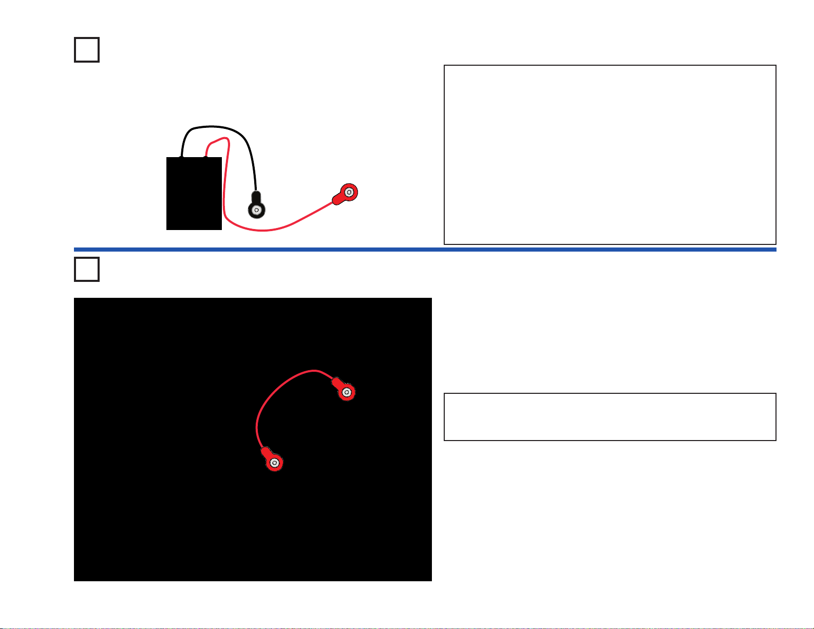
Build the circuit shown, it is the same basic oscillator circuit you have
been using. Touch the the loose ends of the jumper wires to opposite
ends of the rectangles you drew, you should hear a sound like an
alarm. Note: You may get better electrical contact between the wires
and the drawings if you wet the metal with a few drops of water or
saliva.
Making the drawn resistors longer should increase the resistance
while making them wider should reduce the resistance. So all 4
rectangles should produce the same sound, though you will see
variations due to how thick and evenly you filled in the rectangles, and
exactly where you touch the wires. If your 4 shapes don’t sound
similar then try improving your drawings.
Be sure to wash your hands after this project.
Shapes to be drawn.
Use a SHARP No. 2 pencil, draw on
a hard surface, press hard and fill in
several times for best results.
Project #516 Drawing Resistors
Page 12
-11-
Shape to be drawn.
Use a SHARP No. 2 pencil, draw on
a hard surface, press hard and fill in
several times for best results.
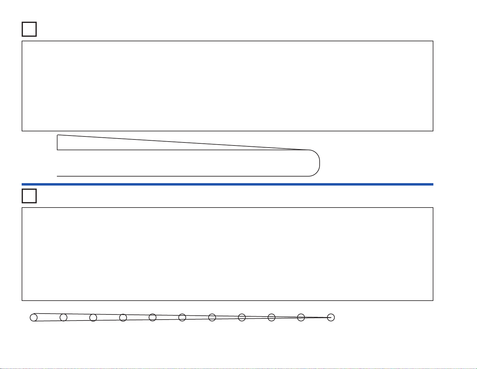
Use the same circuit as project #516, but draw a new shape. A Kazoo
is a musical instrument that is like a one-note flute, and you change the
pitch (frequency) of the sound by moving a plunger up and down inside
a tube.
As before, take a pencil (No. 2 lead is best but other types will also
work), SHARPEN IT again, and fill in the shape you see below. For best
results, SHARPEN IT again, place a hard flat surface between this
page and the rest of this booklet while you are drawing. Press hard
(but don’t rip the paper). Fill in eac h se veral times to be sure you have
a thick, even layer of pencil lead, and try to avoid going out of the
boundaries. Where the shape is just a line, draw a thick line and go
over it several times. The black ink in this manual is an insulator just
like paper, so you have to write over it with your pencil.
Take one loose wire and touch it to the widest part of this shape, at the
upper left. Take the other loose wire and touch it just to the right of the
first wire. You should hear a high-pitch sound. How do you think the
sound will change as you slide the second wire to the right? Do it, slowly
sliding all the way around to the end. The sound changes from high
frequency to low frequency, just like a kazoo. Note: You may get better
electrical contact between the wires and the drawings if you wet the
wires with a few drops of water or saliva.
Shape to be drawn.
Use a SHARP No. 2 pencil, draw on
a hard surface, press hard and fill in
several times for best results.
1 2 3 4 5 6 7 8 9 10 11
Project #517 Electronic Kazoo
Project #518
Electronic Kazoo (II)
Use the same circuit as project #516, but fill in the new shape shown
here.
Take one loose jumper wire and touch it to the left circle. Take the other
loose wire and touch it to each of the other circles. The various circles
produce different pitches in the sound, like notes. Since the circles are
like keys on a piano, you now have an electronic keyboard! See what
kind of music you can play with it. Note: You may get better electrical
contact between the wires and the drawings if you wet the wires with a
few drops of water or saliva.
Now take one loose wire and touch it to the right circle (#11). Take the
other wire and touch it to the circles next to the numbers shown below,
in order:
7 - 5 - 1 - 5 - 7 - 7 - 7
5 - 5 - 5
7 - 7 - 7
7 - 5 - 1 - 5 - 7 - 7 - 7 - 7 - 5 - 5 - 7 - 5 - 1
Do you recognize this nursery rhyme? It is “Mary Had a Little Lamb”. By
now you see that you can draw any shape you like and make electronic
sounds with it. Experiment on your own as much as you like. Be sure
to wash your hands after this test.
Page 13
-12-
Use the same circuit as project #516. T ak e the two loose jumper wires
and touch them with your fingers. You should hear a low-frequency
sound. Now place the loose jumpers in a cup of water without them
touching each other. The sound will have a much higher frequency
because drinking water has lower resistance than your body. You can
change the sound by adding or removing water from the cup. If you
add salt to the water then you will notice the frequency increase,
because dissolving salt lowers the resistance of the water.
You can also make a water kazoo. Pour a small amount of water on a
table or the floor and spread it with your finger into a long line. Place
one of the jumper wires at one end and slide the other along the water.
You should get an effect just like the kazoo you drew with the pencil,
though the frequency will probably be different.
Project #519
OBJECTIVE: To use water as a resistor.
Water Resistor
Project #520
OBJECTIVE: To make an adjustable low-frequency oscillator.
Build the circuit, turn on the slide switch (S1), and then press the press
switch (S2). Move the control lever of the adjustable resistor (RV) to
change the frequency.
Two-Transistor
Oscillator
To learn more about how circuits work, visit www.snapcircuits.net or page 85 to find out about our Student Guides.
Page 14

-13-
Turn on the slide switch (S1), the lamp (L2) will be bright and the LED
(D1) will be lit. The diode (D3) allows the batteries to charge up the
470μF capacitor (C5) and light the LED.
Turn off the slide switch, the lamp will go dark immediately but the LED
will stay lit for a few seconds as capacitor C5 discharges through it.
The diode isolates the capacitor from the lamp; if y ou replace the diode
with a 3-snap wire then the lamp will drain the capacitor almost
instantly.
Project #521
OBJECTIVE: To show how a diode works.
Diode
Project #522
OBJECTIVE: To build a rectifier.
Rectifier
This circuit is based on the Trombone project #238. Turn on the slide
switch (S1) and set the adjustable resistor (RV) for mid-range for the
best sound. The LED (D1) will also be lit.
The signal from the power amplifier (U4) to the speaker (SP) is a
changing (AC) voltage, not the constant (DC) voltage needed to light
the LED. The diode (D3) and capacitor (C5) are a rectifier, which
converts the AC voltage into a DC voltage.
The diode allows the capacitor to charge up when the power amp
voltage is high, but also prevents the capacitor from discharging when
the power amp voltage is low. If you replace the diode with a 3-snap
or remove the capacitor from the circuit, the LED will not light.
Page 15

-14-
Set the meter (M2) to the LOW (or 10mA) scale. Place the fan on the
motor (M1) and turn on the slide switch (S1), the meter measures the
current on the other side of the transformer (T1).
As the DC voltage from the battery (B1) spins the motor, the motor
creates an AC ripple in the voltage. This ripple passes through the
transformer using magnetism. The diode and 0.1μF capacitor (C2)
“rectify” the AC ripple into the DC current that the meter measures.
Holding down the press switch (S2) connects the 470μF capacitor
(C5) across the motor. This filters out the AC ripple, so the current
through the meter is greatly reduced but the motor speed is not
affected.
Project #523
OBJECTIVE: To show how what a rectifier does.
Motor Rectifier
Project #524
OBJECTIVE: To show how an SCR works.
SCR Shutdown
In this circuit the press switch (S2) controls an SCR (Q3), which
controls a transistor (Q2), which controls an LED (D1). Set the
adjustable resistor (RV) control lever to the top (toward the press
switch).
Turn on the slide switch (S1); nothing happens. Press and release the
press switch; the SCR, transistor, and LED turn on and stay on. Now
move the adjustable resistor control down until the LED turns off.
Press and release the press switch again; this time the LED comes on
but goes off after you release the press switch.
If the current through an SCR (anode-to-cathode) is above a threshold
level, then the SCR stays on. In this circuit you can set the adjustable
resistor so that the SCR (and the LED it controls) just barely stays on
or shuts off.
!
WARNING: Moving parts. Do not touch the fan or
motor during operation. Do not lean o ver the motor.
Page 16
-15-
SCR’s are often used to control the speed of a motor. The voltage to
the gate would be a stream of pulses, and the pulses are made wider
to increase the motor speed.
Place the fan on the motor (M1) and turn on the slide switch (S1). The
motor spins and the lamp (L2) lights. Wave your hand over the
photoresistor (RP) to control how much light shines on it, this will
adjust the speed of the motor. By moving your hand in a repetitive
motion, you should be able spin the motor at a slow and steady speed.
Project #525
OBJECTIVE: To show how an SCR is used.
SCR Motor Control
Project #526
OBJECTIVE: To show the different types of output from Snap
Circuits®.
Output Forms
Set the meter (M2) to the LOW (or 10mA) scale. This circuit uses all
six forms of output available in Snap Circuits
®
- speaker (SP, sound),
lamp (L1, light), LED (D1, light), motor (M1, motion), 7-segment
display (D7, light), and meter (M2, motion of pointer).
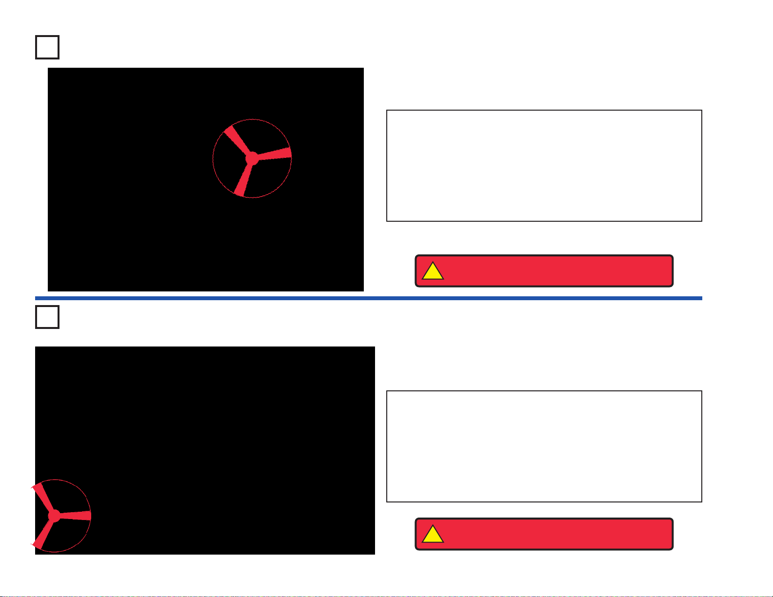
Place the fan on the motor, turn on the slide switch (S1), and shine
light on the solar cell (B2). There will be activity from all six forms of
output. If the motor does not spin, then give it a push with your finger
to start it, or remove the fan.
!
WARNING: Moving parts. Do not touch the fan or
motor during operation. Do not lean o ver the motor.
!
WARNING: Moving parts. Do not touch the fan or
motor during operation. Do not lean o ver the motor.
To learn more about how circuits work, visit www.snapcircuits.net or page 85 to find out about our Student Guides.
Page 17

-16-
This AM radio circuit uses a transistor (Q2) in the amplifier that drives
the speaker (SP). T urn on the slide switch (S1) and adjust the variable
capacitor (CV) for a radio station, then adjust the loudness using the
adjustable resistor (RV).
Project #527
OBJECTIVE: To show the output of an AM radio.
Transistor AM Radio
Project #528
OBJECTIVE: To learn about solar power.
Adjustable Solar
Power Meter
Set the adjustable resistor (RV) for mid-range and the meter (M2) for
the LOW (or 10mA) setting. Turn on the slide switch (S1) and let light
shine on the solar cell (B2). Move the solar cell around different light
sources and adjust the adjustable resistor to change the reading on
the meter.
Place your hand to cover half of the solar cell, the meter reading
should drop by half. When you reduce the light to the solar cell, the
current in the circuit is reduced.
Place a sheet of paper over the solar cell and see how much it
changes the reading on the meter. Then add more sheets until the
meter reads zero.
Page 18
-17-
Turn on the slide switch (S1); nothing
happens. Turn the switch off; the LED
(D1) flashes.
When you turn on the switch, the
electromagnet (M3) stores energy from
the batteries (B1) into a magnetic field.
When you turn off the switch, the
magnetic field collapses and the energy
from it discharges through the LED.
Modify project #529 by replacing the motor (M1) with the
antenna coil (A1). Hold down the press switch (S2) and
then watch the LED (D1) as you release the press switch.
The LED lights briefly but only after the batteries (B2) are
disconnected from the circuit.
This circuit is different from the Fan Blade Storing Energy
project because energy in the antenna coil is stored in a
magnetic field. When the press switch is released, this
field creates a brief current through the LED.
Note that the energy stored in a magnetic field acts like
mechanical momentum, unlike capacitors which store
energy as an electrical charge across a material. You can
replace the antenna with any of the capacitors but the LED
will not light. Energy stored in the magnetic fields of coils
was called electrical momentum in the early days of
electronics.
Antenna Storing
Energy
Project #529
OBJECTIVE: To show that the fan blade stores energy.
Fan Blade Storing Energy
Project #531
OBJECTIVE: To show that the antenna stores energy.
Electromagnet
Storing Energy
Place the fan on the motor (M1). Hold down the press switch (S2) for
a few seconds and then watch the LED (D1) as you release the press
switch. The LED lights briefly but only after the batteries (B1) are
disconnected from the circuit.
Do you know why the LED lights? It lights because the mechanical
energy stored in the fan blade makes the motor act like a generator.
When the press switch is released, this energy creates a brief current
through the LED. If you remove the fan blade from the circuit then the
LED will never light, because the motor shaft alone does not store
enough mechanical energy.
If you rev erse the motor direction, then the LED will light the same wa y,
but the fan may fly off after the LED lights.
This circuit was suggested by
Mike D. of Woodhaven, NY.
Project #530
OBJECTIVE: To show that the
electromagnet stores energy.
!
WARNING: Moving parts. Do not touch the fan or
motor during operation. Do not lean o ver the motor.
Page 19

-18-
Watch the LED’s (D1 & D2) as you press or release
the press switch (S2). The red LED (D1) lights briefly
just as you press the press switch and the green LED
(D2) lights briefly just after you release it, but neither
lights while you hold the press switch down. Why?
When you press the press switch, a surge of current
from the battery charges a magnetic field in the
transformer (T1), which stays constant as the press
switch is held down. Charging the magnetic field
induces an opposing current on the other side of the
transformer, which lights the red LED until the
magnetic fields stabilize.
When you release the press switch (removing the
current from the battery), the magnetic field
discharges. Initially the transformer tries to maintain
the magnetic field by inducing a current on the other
side, which lights the green LED until the resistor (R1)
absorbs the remaining energy.
Note that this project is different from the Antenna
Storing Energy project because there is a magnetic
connection across the transformer, not an electrical
connection.
Modify project #532 by replacing
the transformer (T1) with the relay
(S3), position it with the 3-snap
sides to top and right (as in project
#341).
Hold down the press switch (S2)
and then watch the LED (D1) as
you release the press switch. The
LED lights briefly but only after the
batteries (B1) are disconnected
from the circuit.
The relay has a coil similar to the
one in the transformer, and stores
energy in the same way.
Relay Storing
Energy
Project #532
OBJECTIVE: To show that the transformer stores electrical
energy.
Transformer Storing Energy
Project #534
OBJECTIVE: To show how the transformer works.
Transformer Lights
Hold down the press switch (S2) and then watch the LED (D1) as you
release the press switch. The LED lights briefly but only after the
batteries (B1) are disconnected from the circuit.
This circuit is similar to the Antenna Storing Energy project, and shows
how the coils in the transformer (T1) also store energy in magnetic
fields. When the press switch is released, this energy creates a brief
current through the LED.
Project #533
This circuit is based
on one suggested by
Mike D. of
Woodhaven, NY.
OBJECTIVE: To show that the
relay stores energy.
To learn more about how circuits work, visit www.snapcircuits.net or page 85 to find out about our Student Guides.
Page 20

-19-
Project #535
Project #536
OBJECTIVE: To show how a motor works.
Hear the Motor
Place the fan on the motor (M1). Press the press switch (S2) and
listen to the motor. Why does the motor make sound?
A motor uses magnetism to convert electrical energy into mechanical
spinning motion. As the motor shaft spins around it connects/
disconnects several sets of electrical contacts to give the best
magnetic properties. As these contacts are switched, an electrical
disturbance is created, which the speaker converts into sound.
This circuit was suggested by Andrew M.
of Cochrane, Alberta, Canada
Turn on the slide switch (S1), you hear a strange sound from the
speaker (SP). Push the press switch (S2) and the sound changes to
a high-pitch siren.
The alarm IC (U2) produces a smooth siren sound, but the
electromagnet (M3) distorts the siren into the strange sound you hear.
Adding the 0.1μF capacitor (C2) counters the electromagnet effects
and restores the siren.
OBJECTIVE: To see how the electromagnet can change the
sound from the alarm IC.
Machine Siren
!
WARNING: Moving parts. Do not touch the fan or
motor during operation. Do not lean o ver the motor.
Page 21
-20-
The voltage produced by a motor when it is spinning is called its
Back
Electro-Motive-Force
(Back EMF); this may be thought of as the
motor’s electrical resistance. The motor’s
Front Electro-Motive-Force
is the force it exerts in trying to spin the shaft. This circuit
demonstrates how the Back EMF increases and the current decreases
as the motor speeds up.
Place the fan on the motor (M1) and turn on the slide switch (S1). The
6V bulb (L2) will be bright, indicating that the Back EMF is low and the
current is high.
Turn off the slide switch, remove the fan, and turn the slide switch back
on. The lamp is bright when the motor starts and the lamp dims as the
motor speeds up. Now the Back EMF is high and the current is low.
BE CAREFUL NOT TO TOUCH THE MOTOR WHILE IT SPINS.
Project #537
OBJECTIVE: To demonstrate how the motor works.
Back EMF
Project #538
OBJECTIVE:
To demonstrate how the motor draws more current
to exert greater force when spinning slowly.
Back EMF (II)
Place the fan on the motor (M1). Connect the photoresistor (RP) with
the jumper wires as shown, and hold it next to the 6V lamp (L2) so the
light shines on it.
Turn on the slide switch (S1) and watch how the 6V lamp is bright at
first, but gets dim as the motor speeds up. By moving the
photoresistor (RP) next to or away from the 6V lamp, you should be
able to change the motor speed. To slow the motor down even more,
cover the photoresistor.
When the photoresistor is held next to the 6V lamp, tr ansistor Q2 (with
lamp L1) will try to keep the motor at a constant speed.
!
WARNING: Moving parts.
Do not touch the fan or
motor during operation. Do
not lean over the motor.
!
WARNING: Moving parts. Do not touch the fan or
motor during operation. Do not lean o ver the motor.
Page 22

-21-
Build the circuit and turn on the slide switch (S1), you hear a highfrequency tone. Press the press switch (S2) to lower the frequency b y
increasing the capacitance in the oscillator. Replace the 0.1μF
capacitor (C2) with the 10μF capacitor (C3, “+” on the r ight) to fur ther
lower the frequency of the tone.
Project #539
OBJECTIVE: To make different tones with an oscillator.
Electronic Sound
Project #541
OBJECTIVE: To make a blinking light.
Lighthouse
Build the circuit and turn on the slide switch (S1), the LED (D1) flashes
about once a second.
You can also change the frequency by changing the resistance in the
oscillator. Replace the 100KΩ resistor (R5) with the 10KΩ resistor
(R4), place the 0.1μF capacitor (C2) back in the circuit as before.
OBJECTIVE: To make different tones with an oscillator.
Electronic Sound (II)
Project #540
To learn more about how circuits work, visit www.snapcircuits.net or page 85 to find out about our Student Guides.
Page 23

-22-
Cover the solar cell (B2) and turn on the slide switch (S1), there should
be little or no light from the LED’s (results depend on your batteries).
Shine a bright light on the solar cell and the red (D1) and green (D2)
LED’s should be bright, along with one segment of the 7-segment
display (D7).
This circuit shows how it takes a lot of voltage to turn on a bunch of
diodes connected in a series. Since the transistors (Q1 & Q2) are
used as diodes here, there are six diodes total (D1, D2, D3, D7, Q1,
and Q2). The voltage from the batteries (B1) alone is not enough to
turn them all on at the same time, but the extra voltage produced by
the solar cell is enough to make them bright.
Now push the press switch (S2) and D7 will display “0.”, but it will be
dim unless the light on the solar cell is very bright. With S2 off, all the
current through D7 goes through segment B and makes it bright. With
S2 on, the current through D7 divides evenly between several
segments.
Project #542
OBJECTIVE: To learn more about diodes.
Diode Wonderland
Project #543
OBJECTIVE: To show the difference between the low and high
current meter ranges.
Meter Ranges
Use the LOW (or 10mA) setting on the meter (M2), turn off the slide
switch (S1), and unscrew the 2.5V bulb (L1). The meter should
measure about 2, since the 100KΩ resistor (R5) keeps the current low.
Results will vary depending on how good your batteries are.
Screw in the 2.5V bulb to add the 10KΩ resistor (R4) to the circuit, now
the meter reading will be about 10.
Change the meter to the high-current HIGH (or 1A) setting. Now turn
on the slide switch to add the 100Ω resistor to the circuit. The meter
should read just above zero.
Now press the switch (S2) to add the speaker (SP) to the circuit. The
meter reading will be about 5, since the speaker has only about 8Ω
resistance.
Page 24
-23-
Use the HIGH (or 1A) setting on the meter (M2) and place the fan on the motor (M1). Press the
press switch (S2), the meter will measure a very high current because it takes a lot of power to
spin the fan.
Remove the fan and press the press switch again. The meter reading will be lower since spinning
the motor without the fan takes less power.
Project #544
OBJECTIVE: To measure the motor current.
Motor Current
Project #545
OBJECTIVE: To measure the 2.5V lamp current.
2.5V Lamp Current
Use the circuit from project #544, but replace the motor with the 2.5V lamp (L1). Measure
the current using the HIGH (or 1A) setting on the meter.
Project #546
OBJECTIVE: To measure the 6V lamp current.
6V Lamp Current
Use the circuit from project #544 but replace the motor with the 6V lamp (L2). Measure
the current using the HIGH (or 1A) setting on the meter (M2). Compare the lamp
brightness and meter reading to that for the 2.5V lamp (L1).
Project #547
OBJECTIVE: To measure current through the lamps.
Combined Lamp Circuits
Use the HIGH (or 1A) setting on the meter (M2) and turn on the slide
switch (S1). Both lamps are on and the meter measures the current.
Now turn on the press switch (S2) to bypass the 2.5V lamp (L1). The
6V lamp (L2) is brighter now, and the meter measures a higher
current.
!
WARNING: Moving parts. Do not touch the fan or
motor during operation. Do not lean o ver the motor.
Page 25

-24-
Use the LOW (or 10mA) scale on the meter (M2) and turn the slide
switch (S1) off. Vary the current measured on the meter by moving
your hand over the solar cell (B2) to block some of the light to it. If you
cover the solar cell, then the current immediately drops to zero.
Now turn the slide switch on and watch the meter again as you move
your hand over the solar cell. Now the meter current drops slowly if
you block the light to the solar cell. The 470μF capacitor (C5) is acting
like a rechargeable battery. It keeps a current flowing to the meter
when something (such as clouds) blocks light to the solar cell that is
powering the circuit.
Project #548
OBJECTIVE: To show how a capacitor is like a rechargeable
battery.
Rechargeable Battery
Project #549
OBJECTIVE: To learn about solar power.
Solar Batteries
Place this circuit near different types of lights and press the press
switch (S2). If the light is bright enough, then the LED (D1) will be lit.
Find out what types of light sources make it the brightest.
Solar cells work best with bright sunlight, but incandescent light bulbs
(used in house lamps) also work well. Fluorescent lights (the
overhead lights in offices and schools) do not work as well with solar
cells. Although the voltage produced by your solar cell is 3V just like
the batteries, it cannot supply nearly as much current. If you replace
the LED with the 2.5V lamp (L1) then it will not light, because the lamp
needs a much higher current.
The solar cell (B2) is made from silicon crystals. It uses the energy in
sunlight to make an electric current. Solar cells produce electricity that
will last as long as the sun is bright. They are pollution-free and never
wear out.
To learn more about how circuits work, visit www.snapcircuits.net or page 85 to find out about our Student Guides.
Page 26

-25-
Build the circuit and turn on the slide switch (S1). If there is sunlight
on the solar cell (B2), then the LED (D1) and lamp (L1) will be on.
This circuit uses the solar cell to light the LED and to control the lamp.
The solar cell does not produce enough power to run the lamp directly.
You can replace the lamp with the motor (M1, “+” side on top) and fan;
the motor will spin if there is sunlight on the solar cell.
Project #550
OBJECTIVE: To learn about solar power.
Solar Control
Place the circuit near a bright light and set the adjustable resistor (RV) so that
the meter (M2) reads “10” on the LOW (or 10mA) setting. Now replace the 3snap between points A & B with another component to test, such as a resistor,
capacitor, motor, photoresistor, or lamp. The 100μF (C4) or 470μF (C5)
capacitors will give a high reading that slowly drops to zero.
You can also use the two-spring socket (?1) and place your own components
between its springs to test them.
Project #551
OBJECTIVE: To test the resistance of your components.
Solar Resistance Meter
OBJECTIVE: To learn about solar power.
Solar Diode Tester
Use the same circuit to test the red and green LED’s (D1 & D2), and the diode
(D3). The diode will give a higher meter reading than the LED’s, and all three
will block current in one direction.
Project #552
!
WARNING: Moving parts. Do not touch the fan or
motor during operation. Do not lean o ver the motor.
Page 27

-26-
Project #553
OBJECTIVE: To test your NPN transistor.
Solar NPN Transistor
Tester
This circuit is just like the one in project #551, but tests the NPN
transistor (Q2). The meter will read zero unless both switches (S1 &
S2) are on, then the adjustable resistor (RV) sets the current. If you
have the same light and RV setting as project #552 with the diode
(D3), then the meter (M2) reading will be higher with the transistor.
You can replace the NPN transistor with the SCR (Q3), it works the
same way in this circuit.
Project #554
OBJECTIVE: To test your PNP transistor.
Solar PNP Transistor
Tester
This circuit is just like the one in project #551, but tests the PNP
transistor (Q1). The meter (M2) will read zero unless both switches
(S1 & S2) are on, then the adjustable resistor (RV) sets the current. If
you have the same light and RV setting as project #552 with the diode
(D3), then the meter reading will be higher with the transistor.
Page 28

-27-
Project #555
OBJECTIVE: To compare the voltage of the solar cell to the
battery.
Solar Cell vs. Battery
Set the meter (M2) to the LOW (or 10mA) scale. Press the press
switch (S2) and set the adjustable resistor (RV) so that the meter
reads “5”, then release it.
Now turn on the slide switch (S1) and vary the brightness of light to the
solar cell (B2). Since the voltage from the batteries (B1) is 3V, if the
meter reads higher than “5”, then the solar cell voltage is greater than
3V. If the solar cell voltage is greater and you have rechargeable
batteries (in B1), then turning on both switches at the same time will
use the solar cell to recharge your batteries.
Project #556
OBJECTIVE: To compare the voltage of the solar cell to the
battery.
Solar Cell vs. Battery (II)
Set the meter (M2) to the LOW (or 10mA) scale. Tur n on the slide
switch (S1) and vary the brightness of light to the solar cell (B2). If the
meter reads zero, then the battery voltage is higher than the voltage
produced by the solar cell.
If the meter reads greater than zero, then the solar cell voltage is
higher. If the batteries are rechargeable then the solar cell will
recharge them until the voltages are equal.
To learn more about how circuits work, visit www.snapcircuits.net or page 85 to find out about our Student Guides.
Page 29

-28-
Project #557
OBJECTIVE: To use the sun to make music.
Solar Music
Set the meter (M2) to the LOW (or 10mA) scale. With the slide switch
(S1) off, make sure y ou have enough light on the solar cell (B2) for the
meter to read 7 or higher. Now turn on the slide switch and listen to
the music. When it stops, clap your hands and it should resume.
The meter is used to measure if the solar cell can supply enough
current to operate the music IC (U1).
Project #558
OBJECTIVE: To use the sun to make sounds.
Solar Sounds Combo
Set the meter (M2) to the LOW (or 10mA) scale. With the slide switch
(S1) off, make sure y ou have enough light on the solar cell (B2) for the
meter to read 9 or higher. Now turn on the slide switch and listen to
sounds from the alarm (U2) and space war (U3) IC’s. Wav e your hand
over the photoresistor (RP) to change the sounds.
The meter is used to measure if the solar cell can supply enough
current to operate the alarm and space war IC’s. This project needs
more light than project #557, since two IC’s are used here.
Page 30

-29-
Project #559
OBJECTIVE: To use the sun to make alarm sounds.
Solar Alarm
Set the meter (M2) to the LOW (or 10mA) scale. With the slide switch
(S1) off, make sure you have a bright light on the solar cell (B2) so the
meter reads 10 or higher. Now turn on the slide switch and listen to
the sound.
The meter is used to measure if the solar cell can supply enough
current to operate the alarm IC (U2). Some types of light are better
than others, but bright sunlight is best.
Project #560
OBJECTIVE: To use the sun to make alarm sounds.
Better Solar Alarm
Set the meter (M2) to the LOW (or 10mA) scale. With the slide switch
(S1) off, make sure y ou have enough light on the solar cell (B2) for the
meter to read 8 or higher. Now turn on the slide switch and listen to
the sound.
This circuit uses the transformer (T1) to boost the current to the
speaker (SP), allowing it to operate with less pow er from the solar cell.
Compare how much light it needs to project #559, which doesn’t have
a transformer.
You can change the sound from the alarm IC (U2) using the same
variations listed in projects #61-65.
Page 31

-30-
Project #561
OBJECTIVE: To use the sun to make alarm sounds.
Photo Solar Alarm
Project #562
OBJECTIVE: To use the sun to make space war sounds.
Solar Space War
Set the meter (M2) to the LOW (or 10mA) scale. With the slide switch
(S1) off, make sure y ou have enough light on the solar cell (B2) for the
meter to read 8 or higher. Now turn on the slide switch and listen to
the space war sounds.
Set the meter (M2) to the LOW (or 10mA) scale. With the slide switch
(S1) off, make sure y ou have enough light on the solar cell (B2) for the
meter to read 6 or higher. Now turn on the slide switch and listen to
the alarm. Cover the photoresistor (RP) to stop the alarm.
The whistle chip (WC) needs less power to make noise than the
speaker (SP), so this circuit can operate with less light on the solar cell
than projects #559 and #560. But the sound from the circuits with the
speaker is louder and clearer.
You can change the sound from the alarm IC (U2) using the same
variations listed in projects #61-65.
To learn more about how circuits work, visit www.snapcircuits.net or page 85 to find out about our Student Guides.
Page 32

-31-
Project #563
OBJECTIVE: To use the sun to make a combination of sounds.
Solar Music Alarm
Combo
Project #564
OBJECTIVE: To use the sun to make a combination of sounds.
Solar Music Space War Combo
Set the meter (M2) to the LOW (or 10mA) scale. With the slide switch
(S1) off, make sure y ou have enough light on the solar cell (B2) for the
meter to read 8 or higher. Now turn on the slide switch and listen to
the music.
Set the meter (M2) to the LOW (or 10mA) scale. With the slide switch
(S1) off, make sure y ou have enough light on the solar cell (B2) for the
meter to read 8 or higher. Now turn on the slide switch and listen to
the music.
The meter is used to measure if the solar cell can supply enough
current to operate the ICs (U1 & U2).
OBJECTIVE: To use the sun to make a combination of sounds.
Solar Music Space War Combo (II)
Use the circuit from project #564 but replace the speaker (SP) with the whistle
chip (WC). No w the light on the solar cell (B2) doesn’t have to be as bright for
this circuit to work. You can also modify this circuit by replacing the music IC
(U1) with the alarm IC (U2).
Project #565
Page 33

-32-
Project #566
OBJECTIVE: To use the sun to flash lights in a repeating pattern.
Solar Periodic Lights
Project #568
OBJECTIVE: To use the sun to power an AM radio transmitter.
Solar AM Radio
Transmitter
You need an AM radio for this project. Place it next to your circuit and
tune the frequency to where no other station is transmitting.
Set the meter (M2) to the LOW (or 10mA) scale. With the slide switch
(S1) off, make sure y ou have enough light on the solar cell (B2) for the
meter to read 9 or higher. Turn on the slide switch and adjust the
variable capacitor (CV) for the best sound on the radio. Cover the
photoresistor (RP) to change the sound pattern.
Set the meter (M2) to the LOW (or 10mA) scale. With the slide switch
(S1) off, make sure y ou have enough light on the solar cell (B2) for the
meter to read 9 or higher. Now turn on the slide switch and the LED’s
(D1 & D2) will alternate being on and off.
OBJECTIVE: To use the sun to flash lights in a repeating pattern.
Solar Periodic Lights (II)
Project #567
Use the circuit in project #566, except remov e the 3-snap betw een the
music (U1) and alarm (U2) IC’s (base grid locations C2-C4) and add a
2-snap between the music IC and the 100Ω resistor (R1) (base grid
B4-C4). The circuit works the same way but the LED flashing patterns
are different.
Page 34

-33-
Project #569
OBJECTIVE: To build a sun-powered oscillator circuit.
Low Light Noisemaker
Project #570
Low Light Noisemaker (II)
OBJECTIVE: To build a sun-powered oscillator circuit.
Use the circuit from project #569 but replace
the whistle chip (WC) with the 0.1μF
capacitor (C2) to lower the frequency of the
sound. The circuit works the same way.
OBJECTIVE: To build a sun-powered oscillator circuit.
Project #571
Low Light Noisemaker (III)
Set the meter (M2) to the LOW (or 10mA) scale. With the slide switch
(S1) off, make sure you have light on the solar cell (B2) for the meter
to read at least 5 but less than 10.
Turn on the slide switch and it should make a whining sound, adjust
the amount of light to the solar cell to change the frequency of the
sound. Use a brighter light or partially cover the solar cell if there is no
sound at all.
Use the circuit from project #569 but replace
the whistle chip (WC) with the 10μF capacitor
(C3, “+” on the right) to lower the frequency of
the sound. The circuit works the same way
but you hear a ticking sound instead of a
whining sound.
To learn more about how circuits work, visit www.snapcircuits.net or page 85 to find out about our Student Guides.
Page 35

-34-
Project #572
OBJECTIVE: To build a sun-powered oscillator circuit.
Solar Oscillator
Project #574
OBJECTIVE: To learn the principle of an SCR.
Daylight SCR Lamp
Set the meter (M2) to the LOW (or 10mA) scale. Make sure you have
enough light on the solar cell (B2) for the meter to read 3 or higher.
Turn on the slide switch (S1), the lamp (L1) stays off. Push the press
switch (S2) and the SCR (Q3) turns on the lamp and keeps it on. You
must turn off the slide switch to turn off the lamp.
The SCR is a controlled diode. It lets current flo w in one direction, and
only after a voltage pulse is applied to its control pin. This circuit has
the control pin connected to the press switch and solar cell, so you
can’t turn it on if the room is dark.
Set the meter (M2) to the LOW (or 10mA) scale. With the slide switch (S1)
off, make sure you have enough light on the solar cell (B2) for the meter
to read 8 or higher. Now turn on the slide switch and adjust the adjustable
resistor (RV).
You will hear a clicking sound like raindrops or a whine, depending upon
how much light there is.
OBJECTIVE: To build a sun-powered oscillator circuit.
Solar Oscillator (II)
Project #573
Use the circuit from project #572 but replace the 10μF capacitor (C3)
with the 0.02μF or 0.1μF capacitors (C1 & C2) to make the sound a
high-pitch whine.
Page 36

-35-
Project #575
OBJECTIVE: To build a sun-powered oscillator circuit.
Solar Bird Sounds
Set the meter (M2) to the LOW (or 10mA) scale. With the slide switch
(S1) off, make sure y ou have enough light on the solar cell (B2) for the
meter to read 9 or higher. Now turn on the slide switch and listen to
the sound.
For variations on this circuit, replace the 100μF capacitor (C4) with the
10μF capacitor (C3) or replace the speaker (SP) with the whistle chip
(WC).
Project #576
OBJECTIVE: To build a sun-powered oscillator circuit.
Solar Bird Sounds (II)
Set the meter (M2) to the LOW (or 10mA) scale. With the slide switch
(S1) off, make sure y ou have enough light on the solar cell (B2) for the
meter to read 9 or higher. Now turn on the slide switch and listen to
the sound.
For variations on this circuit, install the whistle chip (WC) above the
0.02μF capacitor (C1), or install it across points A & B and remove the
speaker (SP).
Page 37

-36-
Project #577
OBJECTIVE: To learn the principle of an SCR.
SCR Solar Bomb Sounds
Set the meter (M2) to the LOW (or 10mA) scale. With the slide switch
(S1) off, make sure y ou have enough light on the solar cell (B2) for the
meter to read 8 or higher. Turn on the slide switch now; nothing
happens. Press the press switch (S2) and you hear an explosion of
sounds, which continues until you turn off the slide switch.
Project #578
OBJECTIVE: To build a laser sounding circuit.
Flashing Laser LED’s
with Sound
When you press the press switch (S2), the integrated circuit (U2)
should sound like a laser gun. The red (D1) and green (D2) LED’s will
flash simulating a burst of light. You can shoot long repeating laser
bursts or short zaps by tapping the press switch.
To learn more about how circuits work, visit www.snapcircuits.net or page 85 to find out about our Student Guides.
Page 38

-37-
Project #579
OBJECTIVE: To combine U2 with an amplifier.
U2 with Transistor
Amplifier
Project #580
U2 with Transistor
Amplifier (II)
OBJECTIVE: To combine U2 with an amplifier.
Using project #579, remove the diode (D3) to
create a different sound.
OBJECTIVE: To combine U1 with an amplifier.
Project #581
U1 with Transistor
Amplifier (III)
Turn the slide switch (S1) on and the LED’s (D1 & D2) flash as the
speaker (SP) sounds. The output pulses from U2 turns transistor Q2
on and off rapidly. As the transistor turns on, the speaker shorts to
ground and a current flows through it. The current flow through the
speaker causes it to produce a sound. The LED’s show the pulsing
signal from U2 that is turning Q2 on and off.
Using the project #579, replace U2 with U1.
The circuit will now play music.
Page 39

-38-
Project #582
OBJECTIVE: To create a sound circuit.
Loud Sounds
Turn the slide switch (S1) on and you should hear a tone from the
speaker (SP).
Project #583
OBJECTIVE: To see and hear the output from the Space War
Swinging Meter
with Sound
Set the meter (M2) to the LOW (or 10mA) scale. In this project, you
will see and hear the output from the space war IC (U3). The power
amplifier IC (U4) amplifies the signal from U3 in order to drive the
whistle chip (WC) and meter. Turn on the slide switch (S1). The meter
deflects back and forth, as the LED (D1) flashes and the whistle chip
sounds. Replace the whistle chip with the speaker (SP) for a louder
sound. Note that the meter will deflect very little now. Almost all the
signal is across the speaker due to its low resistance.
Page 40

-39-
Project #584
OBJECTIVE: To create a sound circuit.
Motor Sound Using
Transformer
Project #585
OBJECTIVE: To create a sound circuit.
Motor Sound with LED
In this project, you will drive the whistle chip (WC) and LED’ s using the
motor (M1) and transformer (T1). Turn the slide switch (S1) on. The
motor begins spinning and the red LED (D1) lights. Now press the
press switch (S2), the voltage generated from the transformer is now
across the whistle chip and green LED (D2). The whistle chip sounds
as the green LED lights.
OBJECTIVE: To create a sound circuit.
Motor Sound with LED (II)
Project #586
Modify project #585 by replacing the 6V lamp (L2) with the speaker
(SP). Now the speaker (SP) will also output sound.
!
WARNING: Moving parts. Do not touch the fan or
motor during operation. Do not lean o ver the motor.
Turn the slide switch (S1) on and then rapidly turn on and off the press
switch (S2). This causes a magnetic field to expand and collapse in
the transformer (T1). The small voltage generated is then amplified by
the power amplifier IC (U4) and the speaker (SP) sounds. Replace
switch S2 with the motor (M1, leave the fan off) and you can hear how
fast the motor spins. To hear the sound better, connect the speaker to
the circuit using the red and black jumper wires (instead of the 2snaps) and hold it next to your ear.
!
WARNING: Moving parts. Do not touch the fan or
motor during operation.
To learn more about how circuits work, visit www.snapcircuits.net or page 85 to find out about our Student Guides.
Page 41

-40-
Project #587
OBJECTIVE: Using AC and DC current.
AC & DC Current
This circuit creates an AC & DC current. Press the press switch (S2)
a few times and the LED’s flash back and forth. Turning the switch on
and off causes the magnetic field in the transformer (T1) to expand
(green LED D2 lights) and collapse (red LED D1 lights) and current
flows in two directions. Hold the switch down and the green LED
flashes once. Replace the 6V lamp (L2) with the motor (M1). Press
the press switch, the red LED flickers and the speaker sounds, due to
the small current change from the motor spinning.
Project #588
OBJECTIVE: To create a sound circuit.
Noisemaker
Turn on the slide switch (S1) and the relay (S3) generates a buzzing
noise. Increase the voltage across the relay by pressing the press
switch (S2). The tone is higher because the relay’s contacts are
opening and closing faster.
Page 42

-41-
Project #589
OBJECTIVE: To use AC voltage.
AC Voltage
Turn the slide switch (S1) on. The LED’s (D1 & D2) flash so fast that
they appear to be on, and the speaker (SP) sounds. As in other
projects, the relay’s (S3) contacts open and close rapidly. This causes
the magnetic field in the transformer (T1) to expand and collapse,
creating an AC voltage lighting the LED’s.
Project #590
OBJECTIVE: To use AC voltage.
AC Voltage (II)
You can modify project #589 by adding two light bulbs (L1 & L2).
When the slide switch (S1) is turned on, the relay (S3) sounds and the
light bulbs and LED’s (D1 & D2) flash.
Page 43

-42-
Project #591
OBJECTIVE: To use AC voltage.
AC Voltage (III)
This project is similar to project #589. When the slide switch (S1) is
turned on, the relay (S3) sounds and the light bulbs (L1 & L2) and
LED’s (D1 & D2) flash. Now when the press switch (S2) is pressed,
the speaker (SP) also sounds.
Project #592
OBJECTIVE: To create a sound circuit.
Noisemaker (II)
Turn on the slide switch (S1) and the relay (S3) generates a buzzing
noise. Increase the voltage across the relay by pressing the press
switch (S2). The tone changes because the relay’s contacts are
opening and closing faster.
!
WARNING: Moving parts. Do not touch the fan or
motor during operation. Do not lean o ver the motor.
To learn more about how circuits work, visit www.snapcircuits.net or page 85 to find out about our Student Guides.
Page 44

-43-
Project #594
OBJECTIVE: To create a pulsing motor circuit.
Pulsing Motor
Set the meter (M2) to the LOW scale. Turn on the slide s witch (S1) and
now you have a pulsing motor and LED’s circuit. Replace the meter
with the 470μF capacitor (C5, “+” on right) to change the rate the LED’ s
(D1 & D2) flash.
Project #593
OBJECTIVE: To create a sound circuit.
Noisemaker (III)
Turn the slide switch (S1) on and the speaker (SP) sounds as if a
motor is spinning and an alarm is running. The relay’s (S3) contacts
rapidly open and close the battery connection to the circuit causing the
alarm IC (U2) sound to be different.
!
WARNING: Moving parts. Do not touch the fan or
motor during operation. Do not lean o ver the motor.
Page 45

-44-
Project #595 Noisemaker
(IV)
OBJECTIVE: To create a sound
circuit.
Project #597
Noisemaker
(VI)
OBJECTIVE: To create a sound circuit.
Project #599
Noisemaker
(VIII)
OBJECTIVE: To create a
sound circuit.
OBJECTIVE: To create a
sound circuit.
Project #598
Noisemaker
(VII)
Modify project #598 by removing
the motor (M1). Turn on the slide
switch (S1) and press the press
switch (S2) to hear the new
sound.
Modify the sound of project #599
by replacing the whistle chip
(WC) with the meter (M2, “+”
towards right), use the LOW (or
10mA) meter setting. T urn on the
slide switch (S1) and as the
LED’s flash the meter deflects.
Project #600
Noisemaker
(IX)
OBJECTIVE: To create a
sound circuit.
Project #596
Noisemaker
(V)
Modify the sound of project #595
by adding capacitor C4 across
points A & B (+ of C4 on right).
In this project, you’ll see and hear
the output of the alarm IC (U2). Turn
on the slide switch (S1), the LED’s
(D1 & D2) flash, and the speaker
(SP) sounds as the relay (S3)
chatters. Now press the press
switch (S2) and see what happens
when you remove the relay from the
circuit.
Modify project #596 by replacing the
capacitor C4 with the motor (M1, position it
with the “+” on the left and don’t place the f an
on it). Turn on the slide switch (S1), the
LED’s flash, and the speaker (SP) sounds as
the relay (S3) chatters. Now press the press
switch (S2) removing the relay from the
circuit, providing a constant connection to
the battery (B1). The motor speeds up and
the sound from the speaker is not distorted.
!
WARNING: Moving parts.
Do not touch the fan or
motor during operation. Do
not lean over the motor.
OBJECTIVE: To create a sound circuit.
Modify project #597 replacing
the speaker (SP) with the whistle
chip (WC) and placing the fan
onto the motor (M1). Turn on the
slide switch (S1) and the fan
spins, lights flash, and the relay
(S3) chatters. Now try to launch
the fan by pressing the press
switch (S2) down for about five
seconds and releasing it.
Page 46

-45-
Project #601
OBJECTIVE: To create a sound circuit.
Alarm Power
Project #602
Alarm Power (II)
OBJECTIVE: To create a sound circuit. OBJECTIVE: To hear the sounds of the night.
Project #603
Night Sounds
In this project, the alarm IC (U2) powers the motor (M1), meter (M2)
and LED’s (D1 & D2). Leave the fan off of the motor. Set the meter to
the LOW (or 10mA) position and turn on the slide switch (S1). The
circuit pulses the meter, motor, and LED’s.
Remove the motor (M1) from the circuit and now the circuit pulses
around 1Hz.
Simulate the sound of a forest at night by replacing the motor (M1) in
project #601 with the whistle chip (WC).
!
WARNING: Moving parts. Do not touch the motor
during operation.
To learn more about how circuits work, visit www.snapcircuits.net or page 85 to find out about our Student Guides.
Page 47

-46-
Project #604
OBJECTIVE: To power other devices using the alarm IC.
Mega Pulser &
Flasher
In this circuit, you will power many devices using the alarm IC (U2).
Set the meter (M2) to LOW (or 10mA) and turn on the slide switch
(S1). The LED’s (D1 & D2) and bulbs (L1 & L2) flash, the meter
deflects, the whistle chip (WC) sounds, and the motor (M1) spins.
Project #605
OBJECTIVE: To use the alarm IC to flash between “E” & “S”.
“E” & “S” Blinker
This circuit alternately displays letters “E” and “S” by switching
segments “E” and “C” on and off. Segments A, D, F, and G are
connected to ground so they are always lit. Segment “C” is connected
to the base of Q2 and output of U2. The segment “E” is connected to
the collector of Q2. When the output of U2 is low, segment “C” is on
and “E” is off. When the U2’s output is high, the transistor (Q2) turns
on and segment “C” turns off. When the transistor connects the “E”
segment to ground the segment lights, displaying the letter “S”.
!
WARNING: Moving parts. Do not touch the fan or
motor during operation. Do not lean o ver the motor.
Page 48

-47-
Project #606
OBJECTIVE: To use the alarm IC to flash between “2” & “3”.
“2” & “3” Blinker
The circuit switches between numbers “2” & “3” on the display.
Place jumpers from point A to segment C and point B to segment E.
Project #607
OBJECTIVE: To use the alarm IC to flash between “9” & “0”.
“9” & “0” Blinker
The circuit switches between numbers “9” and “0” on the display.
Place a jumper from point A to segment G and segment B to segment C.
Page 49

-48-
Project #608
OBJECTIVE: To use the alarm IC to flash between “3” & “6”.
“3” & “6” Blinker
The circuit switches between numbers “3” & “6” on the display.
Place a jumper from segment C to segment D and segment B to
point A.
Project #609
OBJECTIVE: To use the alarm IC to flash between “c” & “C”.
“c” & “C” Blinker
The circuit switches between letters “c” & “C” on the display.
Place a jumper from point A to segment G and point B to segment A.
To learn more about how circuits work, visit www.snapcircuits.net or page 85 to find out about our Student Guides.
Page 50

-49-
Project #610
OBJECTIVE: To use the alarm IC to flash between “O” & “o”.
“O” & “o” Blinker
The circuit switches between upper case “O” and lower case “o”.
Place a jumper from point A to segment G. The DP segment will also
light.
Project #611
OBJECTIVE: To use the alarm IC to flash between “b” & “d”.
“b” & “d” Blinker
The circuit switches between letters “b” & “d” on the display.
Place a jumper from point A to segment B and point B to segment F.
Page 51

-50-
Project #612
OBJECTIVE: To use the alarm IC to flash between “H” & “L”.
“H” & “L” Blinker
The circuit switches between letters “H” & “L” on the display.
Project #613
OBJECTIVE: To use the alarm IC to flash between “A” & “O”.
“A” & “O” Blinker
The circuit switches between letters “A” & “O” on the display.
Place a jumper from point A to segment G. The DP segment will also
light.
Page 52

-51-
Project #614
OBJECTIVE: To construct a circuit that indicates if a door is
open or closed using light.
Open & Closed
Indicator
Switching from letters “O” to “C” requires turning off segments B & C.
Turn on the slide switch (S1), the display lights an “O” indicating an
open door. Cover the photoresistor (RP) with your hand (closed door)
and the letter “C” lights. The photoresistor turns Q2 on and off
depending on the amount of light. When Q2 is on (light on RP) the
voltage at the collector is low, lighting segments B & C. Covering the
RP turns Q2 off and the collector voltage is high now. Segments B &
C turn off and the letter “C” lights.
Project #615
OBJECTIVE: To construct a circuit that indicates if a switch is
open or closed using U4.
Open & Closed Indicator (II)
As in project #614, the display will light an “O” or “C” indicating if the press switch
(S2) is on or off. Turn on the slide switch (S1), the LED (D2) and letter “O” lights.
With no input to U4 the LED lights and the voltage decreases enough so segments
B & C light. Press the press switch S2, the LED turns off and the letter “C” lights.
The voltage at U4’s output increased enough turning the segments off.
OBJECTIVE: To construct a circuit that indicates vibration.
Vibration Indicator
Project #616
Modify project #615 by replacing the press switch (S2) with the whistle chip
(WC). As you tap the whistle chip, U4’s output voltage changes, lighting the
LED (D2) and changing the display from “C” to “O”.
To learn more about how circuits work, visit www.snapcircuits.net or page 85 to find out about our Student Guides.
Page 53

-52-
Project #617
OBJECTIVE: To construct a circuit that indicates vibration.
Vibration Sounder
Project #618
OBJECTIVE: To use the SCR to start a circuit.
SCR Noise Circuit
Turn on the slide switch (S1) and nothing happens. The SCR (Q3)
connects the circuit to the batteries and, until the SCR’s gate goes
high, the circuit is off. Press the press switch (S2) and the motor (M1)
spins and the LED (D2) and bulb (L2) light. Increase the sound from
the speaker (SP) by pressing the press switch.
As the motor (M1) spins, it generates an AC voltage amplified by U4.
The output from U4 lights the LED (D2) and makes noise from the
speaker (SP). With the fan not installed, turn on the slide switch (S1)
and you hear the high tone of the spinning motor. Now, install the fan
and hear the difference.
!
WARNING: Moving parts. Do not touch the fan or
motor during operation. Do not lean o ver the motor.
!
WARNING: Moving parts. Do not touch the fan or
motor during operation. Do not lean o ver the motor.
Page 54

-53-
Project #619
OBJECTIVE: Control bulbs L1 & L2 with an SCR and
transistor.
SCR & Transistor
Switch
Turn the slide switch (S1) on and then press the press switch (S2), both
bulbs (L1 & L2) light, but only L2 sta ys on when S2 is released. To stay
on, the transistor (Q2) requires a continuous voltage but the SCR only
needs a pulse. The speaker (SP) may not make any sound.
Project #620
OBJECTIVE: Increase the speed of a motor using an SCR and
transistor.
Two-speed Motor
If you turn on either switch (S1 or S2) alone, nothing happens. But if
you turn on the slide switch (S1) and then press the press switch (S2),
the lamps (L1 & L2) light and the motor (M1) spins. The SCR (Q3)
keeps the 6V lamp (L2) on and the motor spinning after you release
the press switch. If you hold the press switch down, then the 2.5V
lamp (L1) stays on and the motor spins faster.
!
WARNING: Moving parts. Do not touch the fan or
motor during operation. Do not lean o ver the motor.
Page 55

-54-
Project #621
OBJECTIVE: To decrease the speed of a motor using an SCR
and transistor.
Two-speed Motor (II)
Instead of increasing the motor’s speed as in project #620, pressing the
press switch (S2) decreases the speed. In this circuit, the transistor
(Q2) is in parallel with the SCR (Q3). Pressing S2 turns on Q2 and the
voltage across the motor (M1) decreases.
Project #622
OBJECTIVE: To show the effects of current flow.
Current Flow
Set the meter (M2) to the LOW (or 10mA) position. Turning on the
slide switch (S1) connects the motor (M1), meter and 2.5V lamp (L1)
to the lower battery (B1) pack. The motor rotates clockwise and the
meter deflects right. Now turn off the slide switch and press the press
switch (S2). Now, current from the upper battery causes the motor to
rotate in the opposite direction. If you place the batteries in series by
turning on the slide switch and then pressing the press switch, only the
bulbs (L1 & L2) light.
!
WARNING: Moving parts. Do not touch the fan or
motor during operation. Do not lean o ver the motor.
!
WARNING: Moving parts. Do not touch the fan or
motor during operation. Do not lean o ver the motor.
To learn more about how circuits work, visit www.snapcircuits.net or page 85 to find out about our Student Guides.
Page 56

-55-
Project #623
OBJECTIVE: To build an AM radio with LED’s.
AM Radio
with Power LED’s
Set the adjustable resistor (R V) to the middle position and turn the slide
switch (S1) on. Tune the radio by adjusting the v ariab le capacitor (CV).
The LED’s (D1 & D2) flicker as the sound is heard.
Project #624
OBJECTIVE: To record the sounds from the space war IC.
Space War IC
Recording
The circuit records the sounds from the space war IC (U3) into the
recording IC (U6). Turn on the slide switch (S1) and the first beep
indicates that the IC has begun recording. When you hear two beeps,
the recording has stopped. Turn off the slide switch and press the
press switch (S2). You will hear the recording of the space war IC
before each song is played. The lamp (L2) is used to limit current and
will not light.
Place the 2-snap from points A & B onto C & D . Now record a different
sound from U3.
Page 57

-56-
Project #625
OBJECTIVE: To construct an LED flasher.
LED Flasher
Set the adjustable resistor (R V) to the top position and then turn on the
slide switch (S1). The LED’s (D1 & D2) flash at a rate of once per
second. As you adjust RV’s knob down, the LED’s flash faster. When
RV is at the bottom, the LED’s tur n off.
Project #626
OBJECTIVE: To construct an LED flasher with sound.
LED Flasher with Sound
You can modify project #625 by adding a transformer (T1) to drive a speaker
(SP). Set the adjustable resistor (RV) to the top position and turn on the slide
switch (S1). The speaker sounds as the LED (D2) flashes several times per
second. Increase the rate by moving RV’s knob down.
OBJECTIVE: To construct an LED flasher with sound.
LED Flasher with Sound (II)
Project #627
Modify the frequency by replacing the 0.1μF capacitor (C2) with the 10μF
capacitor (C3, “+” side on the right).
Page 58

-57-
Project #628
OBJECTIVE: To build a variable stepper motor.
Stepper Motor
Adjust the adjustable resistor
(RV)
to the middle position and turn on
the slide switch (S1). As the circuit oscillates, the motor (M1) moves a
short distance as the speaker (SP) sounds. Adjust the adjustable
resistor to different positions seeing how it affects the motor and
speaker.
Project #629
OBJECTIVE: To change the sound of the music IC.
Crazy Music IC
Set the adjustable resistor (R V) to the far left position and turn the slide
switch (S1) on. The relay’s (S3) contacts open and close shorting U1
to ground, causing the sound level to change.
!
WARNING: Moving parts. Do not touch the fan or
motor during operation. Do not lean o ver the motor.
To learn more about how circuits work, visit www.snapcircuits.net or page 85 to find out about our Student Guides.
Page 59

-58-
Project #630
OBJECTIVE: To add sound to a stepper motor circuit.
Stepper Motor w/ Sound
Modify project #630 by removing the speaker (SP) and replacing it with the lamp (L1).
Now when you turn the slide switch (S1) on, the lamp lights as the motor spins.
Set the adjustable resistor (RV) to the middle position. Turn the slide switch (S1) on and
the motor (M1) pulses on and off as the speaker (SP) sounds. As the circuit oscillates,
the relay’s (S3) contacts open and close shorting the motor and speaker to ground. See
how much you can adjust the adjustable resistor before the motor turns off or
continuously spins.
Project #631
OBJECTIVE: To add light to a stepper motor circuit.
Stepper Motor w/ Light
Project #632
OBJECTIVE: To display the letter “P” as the alarm IC sounds.
Police Siren with
Display
Turn the slide switch (S1) on and the speaker (SP) sounds as the letter
“P” lights. You also hear the music IC (U1) playing in the background.
The alarm IC (U2) plays as long as the music IC is on since U2 is
connected to U1’s output. After 20 seconds, the circuit turns off for 5
seconds and then starts again.
!
WARNING: Moving parts. Do not touch the fan or
motor during operation. Do not lean o ver the motor.
Page 60

-59-
Project #633
OBJECTIVE: To control the alarm IC with an oscillator circuit.
Oscillator Alarm
Set the adjustable resistor (RV) to the far left and turn the slide switch (S1) on.
The speaker (SP) sounds only once. Slo wly mov e the adjustab le resistor to the
right, the speaker momentarily sounds. As you move the adjustable resistor to
the right, the alarm is on continuously. The adjustable resistor controls the
frequency of the oscillator circuit (C3, C5, Q1, Q2) by adjusting the voltage at
Q2’s base. The relay (S3) switches the alarm IC (U2) on and off.
Project #635
OBJECTIVE: To control the space war IC with an oscillator circuit.
Tapping U3
Set the adjustable resistor (RV) to the middle position and turn the
slide switch (S1) on. This is another example using the oscillator that
switches the power on and off creating sound. Alter the sound by
adjusting the adjustable resistor.
OBJECTIVE: To control the alarm IC with an oscillator circuit.
Oscillator Alarm (II)
Project #634
Using a single snap, connect the red LED (D1, “+” side on point A)
across points A & B. Turn the slide switch (S1) on and the circuit has
a different sound now.
OBJECTIVE: To control the space war IC with an oscillator circuit.
Tapping U3 (II)
Project #636
Connect the motor (M1) across points A & B. Set the adjustable
resistor (RV) to the middle position and turn the slide switch (S1) on.
Now you hear random noise and static from the speaker (SP). The
motor causes the random static and noise from the speaker.
Page 61

-60-
Project #637
OBJECTIVE: To build a simple oscillator that beeps.
Adjustable Beeper
Turn the slide switch (S1) on and this simple oscillator circuit outputs
a beep from the speaker (SP). Change the frequency by adjusting the
adjustable resistor (RV).
Project #638
OBJECTIVE: To create the sound of a cat’s meow.
Electronic Meow
Turn off the slide switch (S1) and then press and release the press
switch (S2). You hear a “cat’s meow” from the speak er (SP). Now turn
the slide switch (S1) on and the sound is lower and lasts longer . Adjust
the adjustable resistor (RV) while the sound is fading away.
OBJECTIVE: To add the photoresistor to project #638.
Electronic Meow (II)
Project #639
Replace the 10KΩ resistor (R4) with the photoresistor (RP). Wave
your hand over photoresistor as you press down on the press switch
(S2).
To learn more about how circuits work, visit www.snapcircuits.net or page 85 to find out about our Student Guides.
Page 62

-61-
Project #640
OBJECTIVE: To construct an LED strobe light.
Strobe Light
This is an example of how a large strobe light works. Turn the slide
switch (S1) on and the LED (D2) flashes at a certain frequency. Adjust
the frequency by adjusting the adjustable resistor (RV). Now add
sound by replacing the 100Ω resistor (R1) with the speaker (SP). Each
time the LED lights, the speaker sounds.
Project #641
OBJECTIVE: To demonstrate the operations of the AND gate.
AND Gate
In digital electronics, there are two states, 0 & 1. The AND gate performs
a logical “and” oper ation on two inputs , A & B . If A AND B are both 1, then
Q should be 1. The logic table below shows the state of “Q” with different
inputs and the symbol for it in circuit diagrams.
In the circuit, the S1 & S2 switches represent inputs A & B, and the D7
display represents output Q.
A B Q D7
0 0 0 “L”
1 0 0 “L”
0 1 0 “L”
1 1 1 “H”
A
B
Q
AND Gate
Page 63

-62-
Project #642
OBJECTIVE: To demonstrate the operations of the NAND gate.
NAND Gate
Project #643
OBJECTIVE: To demonstrate the operations of the OR gate.
OR Gate
The NAND gate works the opposite of the AND as shown in the logic
chart.
In the circuit, the S1 & S2 switches represent inputs A & B, and the D7
display represents output Q.
The basic idea of an OR gate is: If A OR B is 1 (or both are 1), then
Q is 1.
In the circuit, the S1 & S2 switches represent inputs A & B, and the D7
display represents output Q.
A B Q D7
0 0 1 “H”
1 0 1 “H”
0 1 1 “H”
1 1 0 “L”
A B Q D7
0 0 0 “L”
1 0 1 “H”
0 1 1 “H”
1 1 1 “H”
A
B
Q
NAND Gate
A
B
Q
OR Gate
Page 64

-63-
Project #644
OBJECTIVE: To demonstrate the operations of the NOR gate.
NOR Gate
Project #645
OBJECTIVE: To demonstrate the operations of the “exclusive
or” XOR gate.
XOR Gate
The NOR gate works the opposite of the OR. In the circuit, the S1 &
S2 switches represent inputs A & B, and the D7 display represents
output Q.
In an XOR gate the output “Q” is only high when inputs “A” or “B” is set
high (1).
Using the chart, set the switches (S1 & S2) to the different states. The
display (D7) lights the letter “H” only when either switch is turned on.
A B Q D7
0 0 1 “H”
1 0 0 “L”
0 1 0 “L”
1 1 0 “L”
A B Q D7
0 0 0 –
1 0 1 “H”
0 1 1 “H”
1 1 0 –
A
B
Q
XOR Gate
A
B
Q
NOR Gate
To learn more about how circuits work, visit www.snapcircuits.net or page 85 to find out about our Student Guides.
Page 65

-64-
Project #646
OBJECTIVE: To build a high pitch oscillator.
High Pitch Oscillator
Project #648
Low Pitch
Oscilla
tor (II)
OBJECTIVE: To modify project #646. OBJECTIVE: To modify project #646.
Project #649
Low Pitch
Oscilla
tor (III)
Replace the 0.1μF capacitor (C2) with the 10μF capacitor (C3) placing
the “+” sign to w ards the top. Turn the slide switch (S1) on; now the circuit
oscillates at a lower frequency.
Replace the 10μF capacitor (C3) with the 470μF capacitor (C5) placing
the “+” sign towards the top. Turn the slide switch (S1) on and the circuit
oscillates at a lower frequency now.
Set the adjustable resistor (RV) to the top position and then turn the
slide switch (S1) on. You hear a high pitch sound and the LED (D1)
flashes at the same rate. Change the oscillator frequency b y adjusting
RV .
OBJECTIVE: To modify project #646.
Low Pitch Oscillator
Project #647
Replace the whistle chip (WC) with the 0.1μF capacitor (C2). Turn the
slide switch (S1) on and now the circuit oscillates at a low er frequency.
Page 66

-65-
Project #650
OBJECTIVE: To use the alarm IC with the 7-segment display.
Segment Jumper
Turn the slide switch (S1) on; segments A, B, and F light and then
segments C, D, and E. The two groups of segments are connected to
different voltages. As the voltage changes from high to low, the
segments toggle back and forth.
Project #651
OBJECTIVE: To use the alarm IC with the 7-segment display.
DP & Zero Flasher
As in project #650, we use the alarm IC (U2) to flash segments and
LED’s. Turn the slide switch (S1) on and the number “0” and the g reen
LED (D2) flash as the speaker (SP) sounds. When they turn off, the
DP segment lights.
Page 67

Project #652
OBJECTIVE: To add LED’s to a stepper motor circuit.
Stepper Motor with
Lamp & LED’s
Set the adjustable resistor (RV) to the middle position. Turn the slide
switch (S1) on, the motor spins, the bulb lights , and then turn off as the
green LED lights.
-66-
Project #653
OBJECTIVE: To drive the motor and display with two IC
modules.
IC Start & Stop
Turn the slide switch (S1) on. As the output from the IC (U2) drives the
transistor (Q1), the motor (M1) spins and the display (D7) lights the
letter “S” and then turns off.
!
WARNING: Moving parts. Do not touch the fan or
motor during operation. Do not lean o ver the motor.
To learn more about how circuits work, visit www.snapcircuits.net or page 85 to find out about our Student Guides.
!
WARNING: Moving parts. Do not touch the fan or
motor during operation. Do not lean o ver the motor.
Page 68

-67-
Project #654
OBJECTIVE: To modify project #653 so the motor slows down.
IC Motor Speed
Turn the slide switch (S1) on. As the output from the IC (U2) drives the
transistor (Q1), the motor (M1) spins and the display (D7) lights.
Instead of turning off as in project #653, the motor slows down and the
red LED (D1) lights.
Modify the circuit by placing a jumper wire across points A & B. Now
the circuit pulses and then runs continuously for a short time.
Project #655
OBJECTIVE: To use the alarm IC to drive the motor, speaker,
LED and bulb.
Sound & Light Flasher
Turn the slide switch (S1) on and the speaker (SP) outputs the sounds
from the alarm IC (U2). The IC also drives the transistor (Q1) causing
the motor (M1) to spin and lights to flash.
!
WARNING: Moving parts. Do not touch the fan or
motor during operation. Do not lean o ver the motor.
!
WARNING: Moving parts. Do not touch the fan or
motor during operation. Do not lean o ver the motor.
Page 69

-68-
Project #656
OBJECTIVE: To learn about the electromagnet.
Electromagnet
Delayer
Build the circuit and turn it on. After a delay of about 2 seconds, the
lamp (L2) will light, but be dim. Replace your batteries if it does not light
at all.
Why does the electromagnet (M3) delay the lamp turn-on? The
electromagnet (M3) contains a large coil of wire, and the batteries have
to fill the coil with electricity before the lamp can turn on. This is like
using a long hose to water your garden - when you turn on the water it
takes a few seconds before water comes out the other end.
Once the lamp is on, the resistance of the wire in the coil keeps the
lamp from getting bright. You can replace the 6V lamp with the 2.5V
lamp (L1), because the coil will protect it from the full battery voltage.
Project #657
OBJECTIVE: To learn about the electromagnet.
Electromagnet
Delayer (II)
Use the LOW (or 10mA) setting on the meter (M2) and turn on the
slide switch (S1). The meter sho ws ho w the current slo wly rises. After
a delay of about 2 seconds, the lamp (L2) will light but be dim.
Page 70

-69-
Project #658
OBJECTIVE: To learn about the electromagnet.
Two-Lamp
Electromagnet Delayer
Build the circuit and turn it on. First the 2.5V lamp (L1) turns on, and
then the 6V lamp (L2) turns on. Both may be dim, replace your
batteries if they do not light at all.
The electromagnet (M3) stores energy, and the batter ies must fill it up
before the lamps become bright. The smaller bulb turns on sooner
because it needs less current to light.
Project #659
OBJECTIVE: To measure the electromagnet current.
Electromagnet
Current
Use the HIGH (or 1A) setting on the meter (M2) to measure the
electromagnet (M3) current. Compare the meter reading to that f or the
motor and lamp current in projects #544-546. Insert the iron core rod
into the electromagnet and see if it changes the meter reading.
To learn more about how circuits work, visit www.snapcircuits.net or page 85 to find out about our Student Guides.
Page 71

-70-
Project #660
OBJECTIVE: To learn how electricity and magnetism are
related.
Electromagnetism
Project #661 Electromagnetism
& Compass
You need a compass for this project (not included). Use the circuit
from project #660, with the iron core rod in the electromagnet (M3).
You may want to use the slide switch (S1) in place of the press switch
(S2), but only turn it on as needed or you will quickly drain your
batteries.
Turn on the slide switch and move the compass around near the edges
of the electromagnet, it will point toward ends of the iron core rod. By
slowly moving the compass around the electromagnet, you can see
the flow of its magnetic field.
The earth has a similar magnetic field, due to its iron core. A compass
points north because it is attracted to this magnetic field. The
electromagnet creates its own magnetic field, and attracts the
compass in a similar way.
Put the iron core rod into the electromagnet (M3). Press the press switch (S2)
and place the electromagnet (M3) near some iron objects like a refrigerator or
a hammer, it will be attracted to them. You can use it to pick up iron objects,
such as nails.
Electricity and magnetism are closely related, and an electric current flowing in
a coil of wire has a magnetic field just like a normal magnet. Placing an iron
rod through the coil magnifies this magnetic field. Notice that when the
electromagnet is attracted to an iron object, its attraction is strongest at the
ends of the iron core rod. If you remove the iron core rod from the
electromagnet then its magnetic properties are greatly reduced – try this:
If you place the electromagnet upside down under a large object like a table,
you can suspend it there. Be careful though, since it will fall when you release
the press switch.
You can use this circuit to see which things are made of iron. Other metals like
copper or aluminum will not be attracted to the electromagnet.
Magnetic Field
Compass
OBJECTIVE: To learn how electricity and magnetism are
related.
Page 72

Use the circuit from project #660, with the iron
core rod in the electromagnet (M3). Press the
press switch (S2) and use the electromagnet to
pick up some paperclips, they will be attracted to
both ends of the iron core rod. See how many
paperclips you can lift at once.
Snap two 2-snaps around a paperclip and
lift them with the electromagnet, as shown
here on the left.
The magnetic field created by the electromagnet occurs in a loop, and is
strongest in the iron core rod in the middle. You can see this loop with
some paperclips:
You can also use the paperclip to lift the iron core rod up from the
electromagnet.
See what other small objects you can pick up . You can only pick up things
made of iron, not just any metal.
-71-
Project #662
OBJECTIVE: To learn how electricity and magnetism are related.
Electromagnetism & Paperclips
Project #663
OBJECTIVE: To show how electricity can lift things using magnetism.
Electromagnet Suction
An electric current flowing in a coil of wire has a magnetic field, which
tries to suck iron objects into its center. You can see this using the circuit
from project #660.
Lay the electromagnet (M3) on its side with the iron core rod sticking out
about half way, and press the press switch (S2). The iron rod gets
sucked into the center.
A lighter iron object will show this better. T ake a paperclip and straighten
it out, then bend it in half.
Place the bent paperclip next to the electromagnet and turn on the switch
to see it get sucked in. Gently pull it out to feel how much suction the
electromagnet has.
Tr y sucking up other thin iron objects, like nails.
Page 73

-72-
Project #664
OBJECTIVE: To show how electricity can lift things using
magnetism.
Electromagnet Tower
Project #665
OBJECTIVE: To learn how electricity and magnetism are
related.
Paperclip Compass
Use the circuit from project #664, but place the iron core rod in the
electromagnet (M3). You may want to use the slide switch (S1) in
place of the press switch (S2), but only turn it on as needed or you will
quickly drain your batteries.
Slide two paperclips together, using their loops.
Turn on the switch and hold the paperclips just above the
electromagnet, without them touching the iron core rod. Watch how
the lower paperclip is drawn toward the iron core rod, and will point
towards it just like a compass.
This circuit gives a dramatic demonstration of how
the electromagnet (M3) can suck up a paperclip.
Take a paperclip and straighten it out, then bend
it in half. Drop it into the electromagnet center,
and then press the press switch (S2) several
times. The paperclip gets sucked into the center
of the electromagnet and stays suspended there
until you release the press switch.
Add two more 1-snaps under the electromagnet
to make it higher, and try this again. Then try
sucking up other thin iron objects, like nails.
Straighten and
bend paperclip
Drop in
To learn more about how circuits work, visit www.snapcircuits.net or page 85 to find out about our Student Guides.
Page 74

Straighten and
bend paperclip
-73-
Project #666
Adjustable Paperclip Suspension
Project #667
OBJECTIVE: To show how electricity can lift things using magnetism.
Adjustable Paperclip w/ Delay
Use the LOW (or 10mA) setting on the meter (M2).
Take a paperclip and straighten it out, bend it in
half, and place it into the electromagnet (M3)
center. Tur n on the press switch (S2) and set the
adjustable resistor (RV) control lever all the way to
the right. The paperclip gets sucked into the center
of the electromagnet and stays suspended there.
Now quickly slide the adjustable resistor lever all
the way to the left, and watch the paperclip and the
meter reading. The paperclip slowly gets lower, as
the meter shows the current dropping. This circuit
is similar to project #666, but the capacitor delays
the effect of changing the adjustable resistor
setting.
Use the LOW (or 10mA) setting on the meter (M2). Take a
paperclip and straighten it out, bend it in half, and drop it
into the electromagnet (M3) center. Turn on the slide
switch (S1) and set the adjustable resistor (RV) control
lever all the way to the right. The paperclip gets sucked
into the center of the electromagnet and stays suspended
there.
Now very slowly move the adjustable resistor lever to the
left, and watch the paperclip and the meter reading. The
paperclip slowly gets lower, as the meter shows the
current dropping. When the current is at zero, the
paperclip is resting on the table.
Add two more 1-snaps under the electromagnet to make
it higher, and try this again. Or try using a different iron
object in place of the paperclip.
Drop in
Straighten and
bend paperclip
OBJECTIVE: To show how electricity can lift things using magnetism.
Drop in
Page 75

-74-
Project #668
OBJECTIVE: To show how electricity can lift things using
magnetism.
Photoresistor
Paperclip Suspension
Project #669
OBJECTIVE: To show how electricity can lift things using
magnetism.
Paperclip Oscillator
Take a paperclip and straighten it out, bend it in
half, and place it into the electromagnet (M3)
center. Turn on the slide switch (S1), and set the
adjustable resistor (RV) control lever to the right.
The paperclip gets sucked into the center of the
electromagnet and stays suspended there. Move
the adjustable resistor lever to the left, and the
paperclip falls.
Now for the fun part: Slowly slide the adjustable
resistor lever until you find a spot where the
paperclip is bouncing up and down. There will be
a clicking sound from the relay (S3).
Take a paperclip and straighten it out, bend it in half, and place it into
the electromagnet (M3) center. Turn on the slide switch (S1), the
paperclip gets sucked into the center of the electromagnet and stays
suspended there.
Now move the adjustable resistor (RV) control lever around while
waving your hand over the photoresistor (RP). Depending on the
adjustable resistor
setting, sometimes covering the photoresistor
causes the paperclip to fall and sometimes it doesn’t. You can also
adjust the light to set the paperclip to different heights.
Drop in
Straighten and
bend paperclip
Drop in
Straighten and bend paperclip
Page 76

-75-
Project #670
OBJECTIVE: To show how electricity can lift things using
magnetism.
Paperclip Oscillator (II)
Project #671
OBJECTIVE: To show how electricity can lift things using
magnetism.
Paperclip Oscillator (III)
Take a paperclip and straighten it out, bend it in
half, and place it into the electromagnet (M3)
center. Turn on the slide switch (S1), and set the
adjustable resistor (RV) control lever to the right.
The paperclip gets sucked into the center of the
electromagnet and stays suspended there. Move
the adjustable resistor lever to the left, and the
paperclip falls.
Now for the fun part: Slowly slide the adjustable
resistor lever until you find a spot where the
paperclip is bouncing up and down. The speaker
(SP) makes a clicking sound.
Take a paperclip and straighten it out, bend it in
half, and place it into the electromagnet (M3)
center. Turn on the slide switch (S1), and set the
adjustable resistor (RV) control lever to the right.
The paperclip gets sucked into the center of the
electromagnet and stays suspended there. Move
the adjustable resistor lever to the left, and the
paperclip falls.
Now for the fun part: Slowly slide the adjustable
resistor lever until you find a spot where the
paperclip is bouncing up and down.
Drop in
Straighten and
bend paperclip
Drop in
Straighten and
bend paperclip
To learn more about how circuits work, visit www.snapcircuits.net or page 85 to find out about our Student Guides.
Page 77

Straighten and
bend paperclip
-76-
Project #672
OBJECTIVE: To show how electricity can lift things using
magnetism.
Paperclip Oscillator (IV)
OBJECTIVE: To show how electricity can
lift things using magnetism.
Take a paperclip and straighten it out, bend it in
half, and place it into the electromagnet (M3)
center. Turn on the slide switch (S1), and set the
adjustable resistor (RV) control lever to the right.
The paperclip gets sucked into the center of the
electromagnet and stays suspended there. Move
the adjustable resistor lever to the left, and the
paperclip falls.
Now for the fun part: slowly slide the adjustable
resistor lever until you find a spot where the
paperclip is bouncing up and down. The LED
(D1) flashes and the speaker (SP) makes a
clicking sound.
Drop in
Project #673
OBJECTIVE: To learn how electricity and
magnetism are related.
Oscillating
Compass
Use the circuit from project #672, but replace
the 100μF capacitor (C4) with a 3-snap wire
and replace the speaker (SP) with the 6V
lamp (L2). The circuit works the same way,
but the lamp flashes like a strobe light.
Project #674
Use the circuit from project #672, but replace
the 100μF capacitor (C4) with a 3-snap wire and
replace the speaker (SP) with the 6V lamp (L2).
Place the iron core rod in the electromagnet
(M3) and don’t use the bent paperclip. Slide two
paperclips together, using their loops.
Turn on the slide switch (S1) and hold the
paperclips just above the electromagnet, without
them touching the iron core rod. Watch how the
lower paperclip is drawn toward the iron core
rod. Notice that the lower paperclip is vibrating,
due to the changing magnetic field from this
oscillator circuit. Compare this circuit to project
#665 (Paperclip Compass).
Paperclip
Oscillator (V)
Page 78

-77-
Project #675
OBJECTIVE: To show how electricity can lift things using magnetism.
High Frequency Vibrator
Project #676
OBJECTIVE: To show how electricity can lift things using magnetism.
High Frequency Vibrator (II)
Take a paperclip and straighten it out, bend it in half, and place it
into the electromagnet (M3) center. Connect the electromagnet
to points A & B with the jumper wires and hold it about 1 inch
above the table. Slide the adjustable resistor (RV) control lever
around slowly, you will hear a clicking sound from the relay (S3).
Adjust the electromagnet height and resistor control lever until
the paperclip vibrates up and down on the table. It will vibrate at
a fast rate but will not move very high. Usually this works best
with the electromagnet about one inch above the table and the
resistor control about mid-way to the right side, but your results
may vary. See how high you can make the paperclip bounce.
Adjust the electromagnet height and resistor control lever to
change the height and frequency of the vibration.
Straighten and
bend paperclip
Take a paper clip and straighten it out, bend it in half, and place it
into the electromagnet (M3) center. Connect the electromagnet to
points A & B with the jumper wires and hold it about 1 inch above
the table. Slide the adjustable resistor (RV) control lever around
slowly, you will hear a clicking sound from the relay (S3) and
speaker (SP).
Adjust the electromagnet height and resistor control lever until the
paper clip vibrates up and down on the table. It will vibrate at a fast
rate but will not move very high. Usually this works best with the
electromagnet about one inch above the table and the resistor
control about mid-way to the right side, but your results may vary.
See how high you can make the paper clip bounce.
Adjust the electromagnet height and resistor control lever to
change the height and frequency of the vibration.
Straighten and
bend paper clip
Page 79

-78-
Project #677
OBJECTIVE: To show how electricity can move things using
magnetism.
Siren Paperclip Vibrator
Take a paperclip and straighten it out, bend it in
half, and place it into the electromagnet (M3)
center. Turn on the slide switch (S1), and the
paperclip should vibrate.
Now press the press switch (S2), the paperclip is
suspended in the air by the electromagnet and a
siren alarm sounds.
Drop in
Straighten and
bend paperclip
Project #678
Alarm
P
aperclip Vibrator
OBJECTIVE: To show how electricity can move things using
magnetism.
OBJECTIVE: To show how electricity can move things using
magnetism.
Project #679
Machine Gun
P
aperclip Vibrator
Use the circuit from project #677, remove the connection between points
A & B and make a connection between points B & C (using a spacer on
point B). The sound and vibration are different now. Compare the
vibration height and frequency to project #677.
Now remove the connection between points B & C and make a
connection between points D & E. The sound and vibration are different
now. Compare the vibration height and frequency to projects #677 and
#678.
To learn more about how circuits work, visit www.snapcircuits.net or page 85 to find out about our Student Guides.
Page 80

-79-
Project #680
OBJECTIVE: To show how electricity can move things using
magnetism.
Alarm Vibrator w/ LED
Take a paperclip and straighten it out, bend it in
half, and place it into the electromagnet (M3)
center. Turn on the slide switch (S1), and the
paperclip should vibrate and LED (D1) flashes.
Now press the press switch (S2), the paperclip is
sucked up by the electromagnet and a siren
alarm sounds.
You can replace the speaker (SP) with the whistle
chip (WC) to change the sound.
Drop in
Straighten and
bend paperclip
Project #681
OBJECTIVE: To show how electricity can move things using
magnetism.
Alarm Vibrator w/ LED (II)
Take a paperclip and straighten it out, bend it in
half, and place it into the electromagnet (M3)
center. Turn on the slide switch (S1), and the
paperclip should vibrate.
Now press the press switch (S2), the paperclip is
sucked up by the electromagnet and the LED
(D1) flashes.
Drop in
Straighten and
bend paperclip
Page 81

-80-
Project #682
OBJECTIVE: To show how electricity can lift things using magnetism.
Relay-Whistle Vibrator
Take a paperclip and straighten it out, bend it in half, and
place it into the electromagnet (M3) center. Connect the
electromagnet to points A & B with the jumper wires and hold
it about 1 inch above the table. Slide the adjustable resistor
(RV) control lev er around slowly, you will hear a clicking sound
from the relay (S3) and buzzing from the whistle chip (WC).
Adjust the electromagnet height and resistor control lever until
the paperclip vibrates up and down on the table. The vibration
pattern may seem complex because it is due to two sources:
the whistle chip and the relay.
Adjust the electromagnet height and resistor control lever to
change the height and frequency of the vibration.
You can also replace the 10KΩ resistor (R4) with the
photoresistor (RP). Waving your hand over it will start or stop
the vibration.
Drop in
Straighten and
bend paperclip
Project #683
OBJECTIVE: To show how electricity can lift things using magnetism.
Relay-Whistle Photo Vibrator
Take a paperclip and straighten it out, bend it in half, and
place it into the electromagnet (M3) center. Connect the
electromagnet to points A & B with the jumper wires and hold
it about 1 inch above the table. Slide the adjustable resistor
(RV) control lever around slowly without covering the
photoresistor (RP), you will hear a clicking sound from the
relay (S3) and buzzing from the whistle chip (WC).
Adjust the electromagnet height and resistor control lever until
the paperclip vibrates up and down on the table. Then wave
your hand over the photoresistor. The vibration patter n may
seem complex because it is due to three sources: the whistle
chip, the relay, and the photoresistor.
Adjust the electromagnet height and resistor control lever to
change the height and frequency of the vibration. Covering
the photoresistor stops the vibration.
Drop in
Straighten and
bend paperclip
Page 82

-81-
Project #684
OBJECTIVE: Introduction to the vibration switch.
Vibration LED
The vibration switch (S4) contains two separate contacts; a spring is
connected to one of the contacts. A vibration causes the spring to
move briefly shorting the two contacts. This simple circuit
demonstrates how the vibration switch works. Build the circuit and the
LED (D1) does not light. Tap the vibration switch or table and the LED
lights for every tap.
The 100KΩ resistor (R5) limits the current to protect the vibration
switch while the transistors allow the vibration switch to control a large
current.
Project #685
OBJECTIVE: To create sound with a tap of your finger.
Vibration Speaker
OBJECTIVE: To use the meter with the vibration switch.
Modify project #685 by replacing the speaker (SP) with the meter (M2).
Place it with the “+” side towards R5 and use the LOW (or 10mA)
setting. Tap the vibration switch (S4) and the meter deflects to the
right. Tap harder on the switch; the switch closes longer and the meter
deflects more to the right.
Measure the Vibration
as You Tap the Switch
Project #686
Build the circuit and turn on the slide switch (S1). When you tap on the vibration switch
(S4), the speaker (SP) sounds. Listen closely because the sound ma y not be v ery loud.
To learn more about how circuits work, visit www.snapcircuits.net or page 85 to find out about our Student Guides.
Page 83

-82-
Project #687
OBJECTIVE: To turn the music IC on and off using the
vibration switch.
Shaky Birthday Song
Connect the vibration switch (S4) to the circuit using the red and black
jumpers. Hold the vibration switch steady in your hand and the music
should not play. Now move your hand, the music should briefly play. If
you continuously shake the switch, the music keeps playing. Turn the
slide switch (S1) on and the music pla ys. Change the sound b y shaking
the vibration switch.
Project #688
OBJECTIVE: To show the effects of horizontal and vertical
direction.
Vibration Detector
Connect the vibration switch (S4) to the circuit using the black and red
jumper wires. Place the s witch horizontally on the table . Rapidly move
the switch from left to right and notice that the LED (D1) does not light.
There is not enough force to expand the internal spring to turn on the
switch. No w mov e the switch up and do wn and see that the LED easily
lights. It requires less force to move the spring back and forth.
You can replace the LED (D1) with the meter (M2), place it with the “+”
side towards R5 and use the LOW (or 10mA) setting. The meter
deflects more when you move the vibration switch up and down.
Page 84

-83-
Project #689
OBJECTIVE: To build an out of balance turn off circuit.
Out of Balance
Project #690
OBJECTIVE: To sound an alarm when something is shaken.
Vibration Alarm
Turn on the slide switch (S1) and shake the circuit or bang on the table;
an alarm will sound. Try banging on the table in a regular patter n, and
see if you can make the alarm sound continuously.
The vibration switch (S4) triggers the SCR (Q3) connecting the relay’s
(S3) coil to the battery (B1). The relay’s contacts switch, turning the
motor (M1) off, and lighting the lamp (L2). The lamp will stay lit until
the slide switch (S1) is turned off.
Turn the slide switch on; the motor starts to spin. If the motor generates
enough vibration, the switch will trigger the SCR, turning off the motor
and lighting the lamp. If the motor keeps spinning, tap on the table to
trigger the vibration switch.
!
WARNING: Moving parts. Do not touch the fan or
motor during operation. Do not lean o ver the motor.
Page 85

-84-
Project #691
OBJECTIVE: To make sounds when something is shaken.
Vibration Space War
Turn on the slide switch (S1) and shake the circuit or bang on the table,
you will hear different sounds. Try banging on the table in a regular
pattern, and see if you can make the sounds continuous.
When the vibration switch (S4) is shaken, the circuit plays out one of
eight sounds.
Project #692
OBJECTIVE: To build a lamp that stays on for a while.
Vibration Light
Turn on the slide switch (S1) and shake the base grid or bang on the
table. The lamp (L1) turns on when there is vibration, and stays on for
a few seconds.
To learn more about how circuits work, visit www.snapcircuits.net or page 85 to find out about our Student Guides.
Page 86

-85-
OTHER FUN ELENCO®PRODUCTS!
For a listing of local toy retailers who carry Snap Circuits®, please visit www.elenco.com or call us toll-free at (800) 533-2441. For Snap
Circuits®upgrade kits, accessories, additional parts, and more information about your parts, please visit www.snapcircuits.net.
Elenco®provides a circuit designer so that you
can make your own Snap Circuits®drawings.
This Microsoft®Word document can be
downloaded from:
www.snapcircuits.net/SnapDesigner.doc
or through the www.snapcircuits.net web site.
Snaptricity Model SCBE-75
Build Over 75 Projects
Learn how electricity and magnetism can be used to make each other, learn
about magnetic fields, how the electricity in your home works, how switches
control the electricity to the lights in your home, and how series and parallel
circuits affect electricity.
Over 40 parts including: Meter, electromagnet, motor, lamps, switches, fan,
compass, and electrodes.
Educational Toy: Projects that relate to electricity in the home and magnetism
and how it is used. Build over 75 projects.
Deluxe Snap Rover
®
Model SCROV-50
Introducing the next generation of the RC Snap Rover®! This version
includes a disc launcher, digital voice recorder, and music sounds.
Over 50 parts allow you to complete over 40 additional projects.
Put your circuits in motion!
• Includes 30 parts
• Build over 20 projects
• Full-color assembly
manual
• Sound effects
Snap Circuits®Green
Alternative Energy Kit
Model SCG-125
Learn about energy sources and how to “think green”. Build o v er 125
projects and have loads of fun learning about environmentallyfriendly energy and how the electricity in your home works. Includes
full-color manual with over 100 pages and separate educational
manual. This educational manual will explain all the forms of
environmentally-friendly energy including: geothermal, hydrogen fuel
cells, wind, solar, tidal, hydro, and others. Contains over 40 parts.
Snap Circuits®LIGHT
Model SCL-175
Build over 175 projects!
Contains over 60 parts
If you want to enhance your Snap
Circuits®experience and get even
smarter, then try
For use with SC-750
Educational Series - teaches Basic Electricity
and Electronics in the everyday world using our
Learn By Doing
®
concept! 80 full-color
pages, and written
with the help of
educators.
Snap Circuits
®
Student Guide
Part # 753307
AC Po w er
Supply
Par t #
AC-SNAP
Replaces the batteries in
Snap Circuits®.
Custom Storage Case
Model SNAPCASE7
Heavy duty plastic case with 2
custom foam inserts for housing
your Snap Circuits
®
parts. Easy to
identify missing components. Also
includes a separate small case to
hold the smaller loose parts.
(for use with SC-750)
• Infrared detector
• Strobe light
• Color changing LED
• Glow-in-the-dark fan
• Strobe integrated circuit (IC)
• Fiber optic communication
• Color organ controlled by iPod
®
or
other MP3 player, voice, and fingers.
Page 87

-86-
OTHER FUN ELENCO®PRODUCTS!
Project Labs
No Soldering Required
Educational Kits
No Soldering Required
500-in-1 Electronic Project Lab
Model MX-909
The purpose of this project is to expand your
understanding of basic transmitters, receivers
and electronic switching theories. Your Turbo
King Car will be built from the ground up. You’ll
learn all about gears, motors, printed circuit
boards, and integrated circuits from our
detailed assembly and training manual.
You will construct each section, explore the
circuitry and troubleshoot it.
Requires 1 9V and 4 “AA” batteries.
Radio-Controlled Race Car
Model FUN-875
By solar power, harness the power of the sun
with this environment-friendly D.I.Y. kit!
You can do a series of do-it-yourself
experiments to acquire the basic knowledge of
solar energy.
You can learn how to make an electrical
circuit, make a solar circuit, how to increase
voltage and current, and how to use solar
power to produce energy for a radio,
calculator, battery charger, and more!
Solar Deluxe Educational Kit
Model SK-40
Everything you need to build 500 exciting electronic
projects. Learn the basics of electronics and put
your knowledge to work creating projects that
explore amplifiers, analog and digital circuits plus
learn how to read schematic diagrams. Includes
built-in breadboard for easy wiring and connection
of components and an LCD (liquid crystal display)
which indicates the information for the experiment
in progress. Includes breadboard and spring hookup methods.
Beginning chemistry set includes 60
fun activities with no chemicals.
Activities include threedimensional bubbles, basic
chemistry, crystal growing,
physics, magnetism, optics,
growing plants, slime &
gook, science tricks, and
chromatography.
Warning: This product
contains magnets.
`
Chemistry 60
Model EDU-7075
This kit is part of our Body Awareness Science Series, exploring the five senses:
sight, hearing, smell, taste, and touch. Perform over 50 fascinating experiments.
Use a genuine stethoscope, make
a telescope with real lenses and
create rainbows with a prism.
Prepare perfume and stink bombs
with chemistry lab equipment.
Learn how to read and send
messages in Braille. Also includes
many activities suitable for party
games.
My Senses
Model EDU-7086
Over 30 fascinating activities all about weather and climate. Build
your own barometer, weather vane, rain gauge, and hydrometer.
Observe the weather traits
and see how they’ll affect
tomorrow’s weather. Make
a rainbow, produce clouds,
lightning, rain, and even a
thunderstorm! Requires
one (1) 9V battery.
Weather
Model EDU-7074
Warning: This product
contains uninflated balloons.
`
Investigate, analyze, decipher and solve the crime!
Over 65 activities with fingerprints, secret messages, chromatography, cipher codes,
identity detection and
more. Kit includes 30X
microscope and necessary
lab equipment.
Requires two (2) “AA”
batteries.
Detectolab
Model EDU-7080
Page 88

ELENCO
®
150 Carpenter Avenue
Wheeling, IL 60090
(847) 541-3800
Website: www.elenco.com
e-mail: elenco@elenco.com
 Loading...