

Page 1
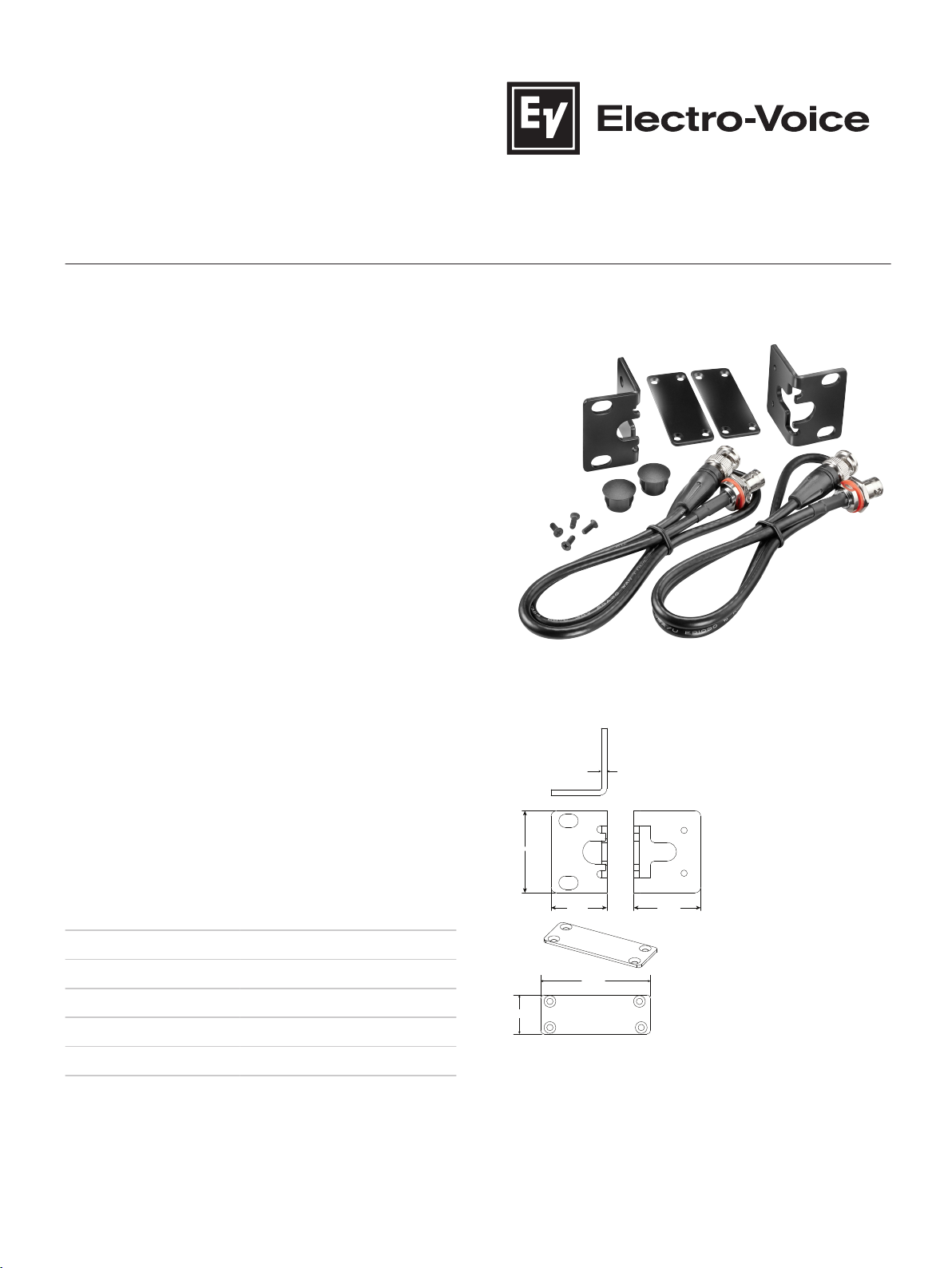
3 mm
30 mm
44 mm
36 mm
21 mm
59 mm
Electro-Voice | RE3-ACC-RMK2 Rack mount kit for two RE3
receivers
RE3-ACC-RMK2 Rack
mount kit for two RE3
receivers
▪ Equips two RE3 receivers for rack mounting
▪ Provides front mounting of antennas or cables
▪ Coupling plates firmly secure receivers together
▪ Two high-quality RG-58 50 Ω front-mount cables
▪ Includes rack ears, coupling plates, cables,
mounting screws, and hole plugs
The RMK2 kit contains all necessary items to couple
and mount two RE3-RX receivers into a 19” rack. The
bridging plates firmly couple two receivers together
ensuring the receivers are held securely in a rack. The
rack ears easily mount to the receiver’s threaded
mounting holes using the provided screws. The
threaded front flange mount ends of the antenna
cables mount into the rack ears and securely mount
either the stock receiver ½ wave antennas, or coax
extension cables for remote antenna applications.
Technical specifications
Coax type: RG-58
Coax impedance: 50 Ω
Dimensions:
Color: Black
Net weight: 8.3 oz. (235 g)
Gross weight: 10.6 oz. (300 g)
Installation/configuration notes
Installing the rack kit
To install the rack kit, do the following:
Page 2
1
Left receiver
t
op view (A)
Right receiver
top view (B)
2
3
4
5
5
FLAT (A)
CXUF
2 | RE3-ACC-RMK2 Rack mount kit for two RE3 receivers
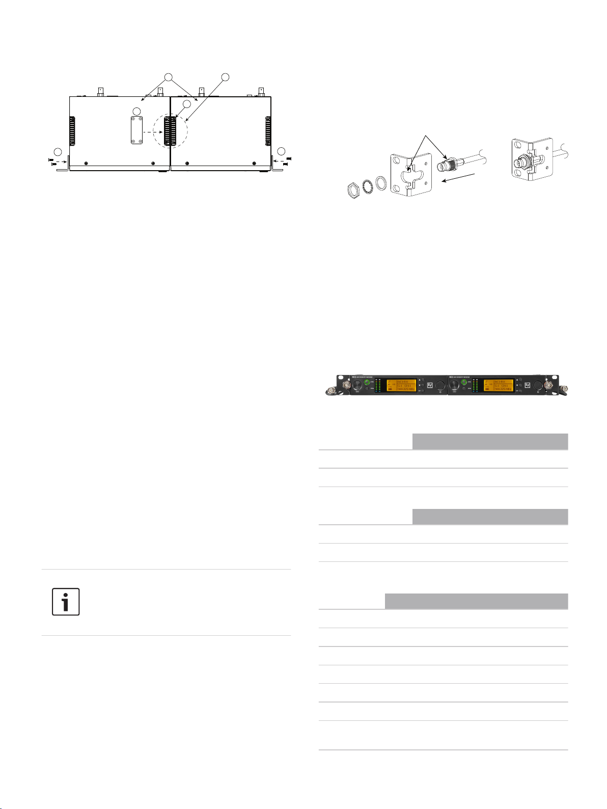
3. While aligning the flat (A) portion of the threaded
connector barrel with the flat portion of the rack ear
front flange opening, slide the threaded barrel
through the opening until it is fully extended through
the rack ear flange.
A Left receiver top view B Right receiver top view
1. On a flat surface, lay out two RE3 receivers side-byside as they will appear in the rack.
The top and bottom of the receivers contain the same
items that will be removed and replaced with coupling
plates.
Locate the skid pads on the top and bottom of each
2.
receiver.
Notice that the right-side skid pad of the left-hand
receiver is adjacent to the left-side skid pad of the righthand receiver.
3.
Remove and save the eight machine screws and set
aside the four skid pads from the top and bottom
coupling sites.
Remember when removing the screws to set them aside.
They will be reused when attaching the coupling plates.
4. Locate and place one of the coupling plates where
the two adjacent skid pads had been on the top.
5. Using four of the screws removed previously, attach
the coupling plate by tightening the screws securely.
6. Turn the units over and repeat this step on the
opposite side.
When all eight screws are tight, the receivers will be
securely coupled together.
7. Locate the rack ears and supplied screws.
Ears will mount on either side of the receiver as they are
the same orientation.
8. Attach the rack ears to the receiver chassis by using
two screws per ear.
The rack ear mounting holes will line up with the pretapped holes in the receiver side.
9. Tighten all four screws securely.
Installing the antenna cables
4. Slide the rubber insulator ring onto the threaded
connector barrel.
Slide the crush washer onto the threaded connector
5.
barrel.
Thread and tighten the nut onto the threaded
6.
connector barrel.
Ensure the nut is tightened securely to the connector
barrel.
7. Repeat steps 4-6 for the other cable and rack ear.
8. Connect the other ends of the antenna cables into
antenna A and antenna B inputs of an antenna
distribution device.
Antenna distribution device options: RE3-ACC-AASP
active antenna splitter or the RE3-ACC-PASP passive
antenna splitter.
Completed assembly
Replacement parts
Order number Description
ESP-EF01U362341 RMK2 bridge plate screws RE3 (4pcs)
ESP-EF01U362356 RKMT antenna hole plugs RE3 (2pcs)
Compatible products
Order number Description
RE3-ACC-AASP 2-in x 8-out antenna splitter 470-960MHz
RE3-ACC-PASP 1 x 2 passive antenna splitter kit
Notice!
Mount the rack ears to each side of the re-
Parts included
Quantity Component
ceiver pair prior to installing the antenna cables.
2 Rack ears
2 Coupling plates
To install the antenna cables, do the following:
2
CXUF front mount antenna cables
1. Locate a CXUF rear to front antenna cable and
determine the cable end containing a threaded
flange-mount connector.
Two CXUF cables are in the kit.
2. Remove the locking nut, crush washer, and rubber
insulator from the threaded flange-mount connector.
2 Plastic hole plugs
4
Mounting screws
1 Engineering datasheet
1 Warranty and product documentation information
card
Page 3

3 | RE3-ACC-RMK2 Rack mount kit for two RE3 receivers
Ordering information
RE3-ACC-RMK2 Rack mount kit for two RE3 receivers
Dual rack mount kit for rack mounting two RE3
receivers, black
Order number RE3-ACC-RMK2
Page 4

4 | RE3-ACC-RMK2 Rack mount kit for two RE3 receivers
Represented by:
Germany:
Bosch Sicherheitssysteme GmbH
Robert-Bosch-Ring 5
85630 Grasbrunn
Germany
www.electrovoice.com
© Bosch Security Systems 2018 | Data subject to change without notice
Document Number F.01U.363.715 | Vs1 | 14. Dec 2018
Bosch Security Systems, Inc.
12000 Portland Avenue South
Burnsville MN 55337
USA
 Loading...