

Page 1
PXM‑12MP Powered Monitor
PXM‑12MP‑EU | PXM‑12MP‑US
en
Installation manual
Page 2

Page 3

PXM-12MP Powered Monitor Table of contents | en 3
Table of contents
1
1.1 Important safety instructions 4
1.2 FCC information 5
1.3 Precautions 5
1.4 Notices 6
2
2.1 System features 8
2.2 Quick setup 9
3
3.1 Floor monitor 11
3.2 Tripod 12
3.3 Pole mount with subwoofer 13
4
4.1 Input panel controls 14
4.2 System status 15
4.3 DSP controls 16
4.4 DSP control menu 16
4.5 DSP parameter definitions 18
5
5.1 Dedicated monitor 20
5.2 Stereo PA 21
5.3 Main PA with subwoofer 22
6
7
7.1 Off Axis Response 27
7.2 Dimensions 29
Safety 4
Description 8
Floor monitor, tripod, and pole mount operation 11
Input panel and DSP 14
Recommended configurations 20
Troubleshooting 23
Technical data 25
Electro-Voice Installation manual 2019-10 | v01 | F.01U.363.983
Page 4
4 en | Safety PXM-12MP Powered Monitor
!
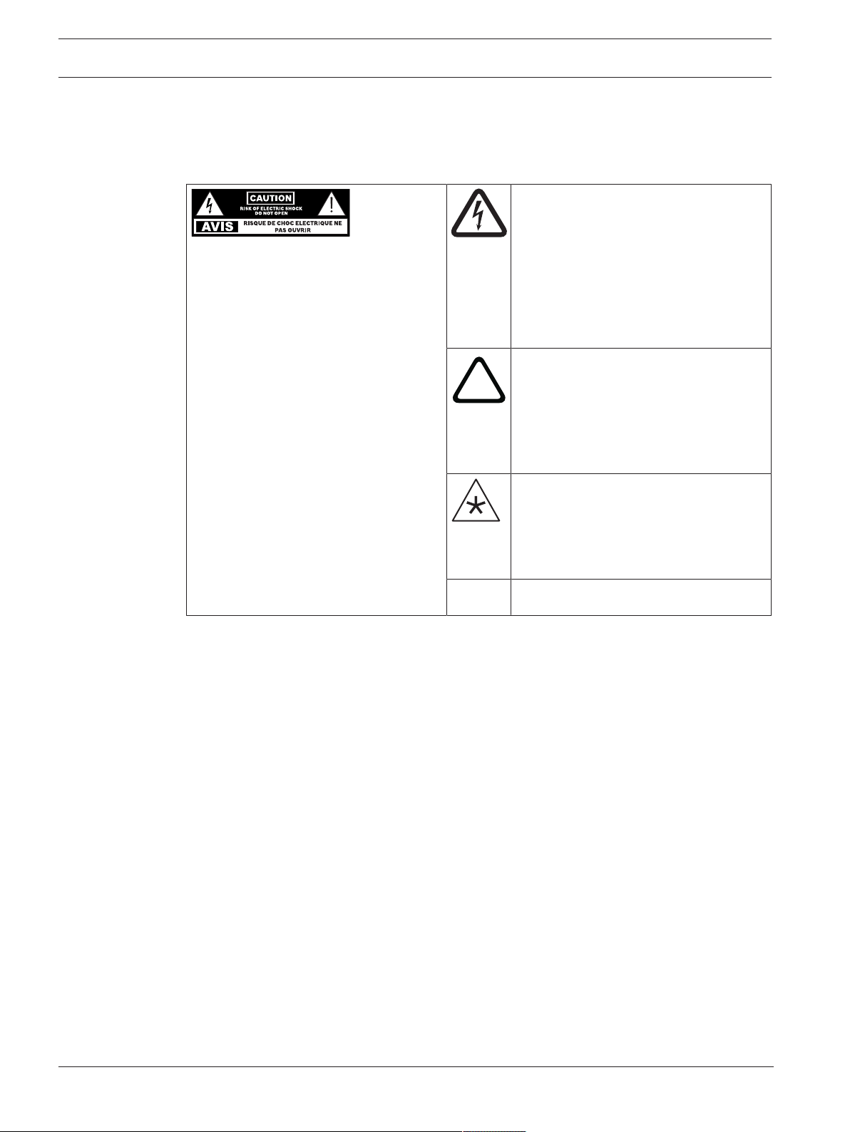
1 Safety
1.1 Important safety instructions
The lightning flash with arrowhead
symbol, within an equilateral triangle is
intended to alert the user to the
WARNING: TO REDUCE THE RISK OF
FIRE OR ELECTRIC SHOCK, DO NOT
OVEREXPOSE THIS APPLIANCE TO RAIN
OR MOISTURE
AVIS: RISQUE DE CHOC ELECTRIQUE,
NE PAS OUVRIR.
WARNING: THE MAINS PLUG OR AC
INLET IS USED AS A DISCONNECT
DEVICE. THE DISCONNECT DEVICE
SHALL REMAIN READILY OPERABLE.
WARNING: CONNECT ONLY TO MAINS
SOCKET WITH PROTECTIVE EARTHING
CONNECTION.
WARNING: TO REDUCE THE RISK OF
ELECTRIC SHOCK, DO NOT REMOVE
COVER (OR BACK) AS THERE ARE NO
USER-SERVICABLE PARTS INSIDE.
REFER SERVICING TO QUALIFIED
PERSONNEL.
presence of uninsulated “dangerous
voltage” within the product’s enclosure
that may be sufficient magnitude to
constitute a risk of electric shock to
persons.
The exclamation point within an
equilateral triangle is intended to alert
the user to the presence of important
operating and maintenance (servicing)
instructions in the literature
accompanying the appliance.
The asterisk within an equilateral
triangle is intended to inform the user to
necessary installation or removal
instructions regarding equipment or
hardware use relating to the system.
1. Read these instructions.
2. Protect the power cord from being walked on or pinched particularly at plugs,
convenience receptacles, and the point where they exit from the apparatus.
3. Only use attachments/accessories specified by the manufacturer.
4. Use only with the cart, stand, tripod, bracket, or table specified by the manufacturer, or
with the apparatus. When a cart is used, use caution when moving the cart/apparatus
combination to avoid injury from tip-over.
5. Unplug the apparatus during lightning storms or when unused for long periods of time.
6. Refer all servicing to qualified service personnel. Servicing is required when the
apparatus has been damaged in any way, such as power-supply cord or plug is damaged,
liquid has been spilled or objects have fallen into the apparatus, the apparatus has been
exposed to rain or moisture, does not operate normally, or has been dropped.
7. Keep these instructions.
8. Heed all warnings.
9. Follow all instructions.
10. Do not use this apparatus near water.
11. Clean only with a dry cloth.
12. Do not block any ventilation openings. Install in accordance with the manufacturer's
instructions.
13. Do not install near any heat sources such as radiators, heat registers, stoves, or other
apparatus (including amplifiers) that produce heat.
2019-10 | v01 | F.01U.363.983 Installation manual Electro-Voice
Page 5
PXM-12MP Powered Monitor Safety | en 5
!
!
14. Do not defeat the safety purpose of the polarized or grounding-type plug. A polarized plug
has two blades with one wider than the other. A grounding type plug has two blades and
a third grounding prong. The wide blade or the third prong is provided for your safety. If
the provided plug does not fit into your outlet, consult an electrician for replacement of
the obsolete outlet.
15. No naked flame sources, such as lighted candles, should be placed on the apparatus.
16. Minimum 60 cm (2 ft) distances around the apparatus for sufficient ventilation.
17. The ventilation should not be impeded by covering the ventilation openings with items,
such as newspapers, table-cloths, curtains, etc.
18. To completely disconnect AC power from this apparatus, the power supply cord must be
unplugged.
19. To reduce the risk of fire or electric shock, do not expose this apparatus to rain or
moisture. The apparatus should not be exposed to dripping or splashing. Objects filled
with liquids, such as vases should not be placed on apparatus.
1.2 FCC information
IMPORTANT: Do not modify this unit! Changes or modifications not expressly approved by the
manufacturer could void the user’s authority, granted by the FCC, to operate the equipment.
Notice!
This equipment has been tested and found to comply with the limits for a Class B digital
device, pursuant to Part 15 of the FCC Rules. These limits are designed to provide reasonable
protection against harmful interference in a residential installation. This equipment generates,
uses and can radiate radio frequency energy and, if not installed and used in accordance with
the instructions, may cause harmful interference to radio communications. However, there is
no guarantee interference will not occur in a particular installation.
If this equipment does cause harmful interference to radio or television reception or receive
audible interference from radio, television or communications equipment, which can be
determined by turning the equipment off and on. The user is encouraged to try to correct the
interference by one or more of the following measures:
– Reorient or relocate the receiving antenna.
– Increase the separation between the equipment and receiver.
– Connect the equipment into an outlet on a circuit different from that to which the
receiver is connected.
– Consult the dealer or an experienced radio/TV/communications equipment technician.
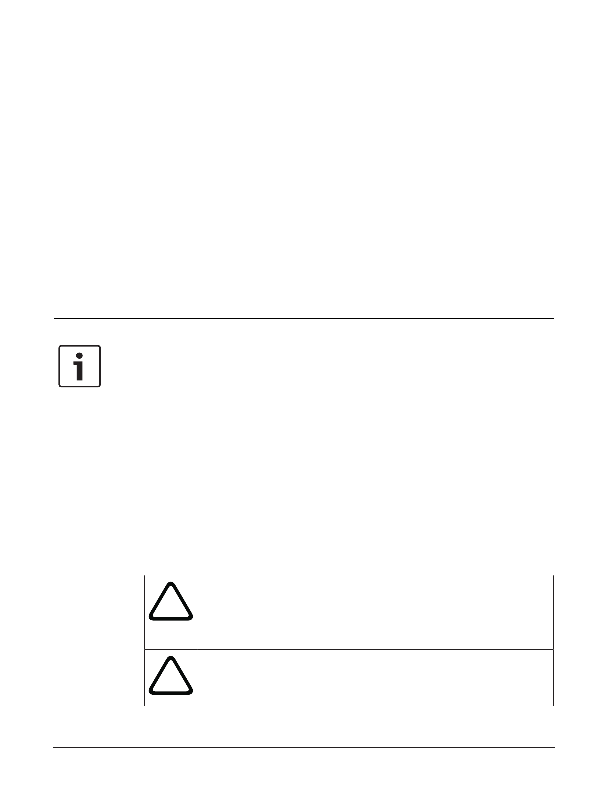
1.3 Precautions
If an Electro-Voice loudspeaker is used outdoors on a sunny day, place the
loudspeaker in a shaded or covered area. The loudspeaker amplifiers have
protection circuits that temporarily shut the loudspeaker off when extremely
high temperatures are reached. This can happen on hot days when the
loudspeaker is in direct sunlight.
Do not use Electro-Voice loudspeakers in an environment where temperatures
are below 0°C (32°F) or exceed +35°C (95°F).
Electro-Voice Installation manual 2019-10 | v01 | F.01U.363.983
Page 6
6 en | Safety PXM-12MP Powered Monitor
!
!
Never expose an Electro-Voice loudspeaker to rain, water, or high moisture.
Electro-Voice loudspeakers are easily capable of generating sound pressure
levels sufficient to cause permanent hearing damage to anyone within normal
coverage distance. Caution should be taken to avoid prolonged exposure to
sound pressure levels exceeding 90 dB.
1.4 Notices
Old electrical and electronic appliances
Electrical or electronic devices that are no longer serviceable must be collected separately and
sent for environmentally compatible recycling (in accordance with the European Waste
Electrical and Electronic Equipment Directive).
To dispose of old electrical or electronic devices, you should use the return and collection
systems put in place in the country concerned.
Copyright and disclaimer
All rights reserved. No part of this document may be reproduced or transmitted in any form by
any means, electronic, mechanical, photocopying, recording, or otherwise, without the prior
written permission of the publisher. For information on getting permission for reprints and
excerpts, contact Electro-Voice.
All content including specifications, data, and illustrations in this manual are subject to change
without prior notice.
2019-10 | v01 | F.01U.363.983 Installation manual Electro-Voice
Page 7
PXM-12MP Powered Monitor Safety | en 7
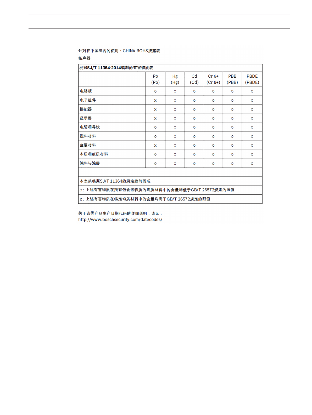
For use in China: CHINA ROHS DISCLOSURE TABLE
Electro-Voice Installation manual 2019-10 | v01 | F.01U.363.983
Page 8

8 en | Description PXM-12MP Powered Monitor
2 Description
The PXM-12MP is a powered, multi-functional coaxial monitor designed for high output and
clear audio intelligibility. It is ideal for applications where the user requires monitoring of
themselves or others, particularly in situations where a primary PA is in use. Multiple inputs
and tuning presets allow for a wide variety of additional applications. It can also double as a
PA with the use of built-in presets and a standard speaker tripod mount.
The system features a coaxial 12” transducer with a 1.75” neodymium compression driver.
These are driven by a Dynacord engineered 2-channel 700 W amplifier and digital signal
processing. The components are housed in a rigid 15 mm plywood enclosure that is protected
by a polyurea-based EV-Coat and an 15 gauge powder-coated steel grille. The system features
multiple handles and a light weight for easy handling and portability.
Thank you for choosing an Electro-Voice powered loudspeaker system. Please take time to
consult the manual to understand all the features built into your EV system and fully utilize its
performance capabilities.
2.1 System features
– Multi-functional monitoring system that is useable as a floor wedge or as a mains PA.
– QuickSmartDSP features best-in-class processing. Easy setup via four presets, sub/top
system-match, three-band EQ, five user-programmable presets, visual monitoring of
limiter status, input level control and meters, and master volume control to optimize gain
structure, all via LCD.
– 700 W Class-D power amplifier designed by Dynacord delivers up to 129 dB peak SPL
utilizing transducers by EV.
– System reliability verified with over 500 hours of abuse and endurance testing.
2019-10 | v01 | F.01U.363.983 Installation manual Electro-Voice
Page 9
PXM-12MP Powered Monitor Description | en 9
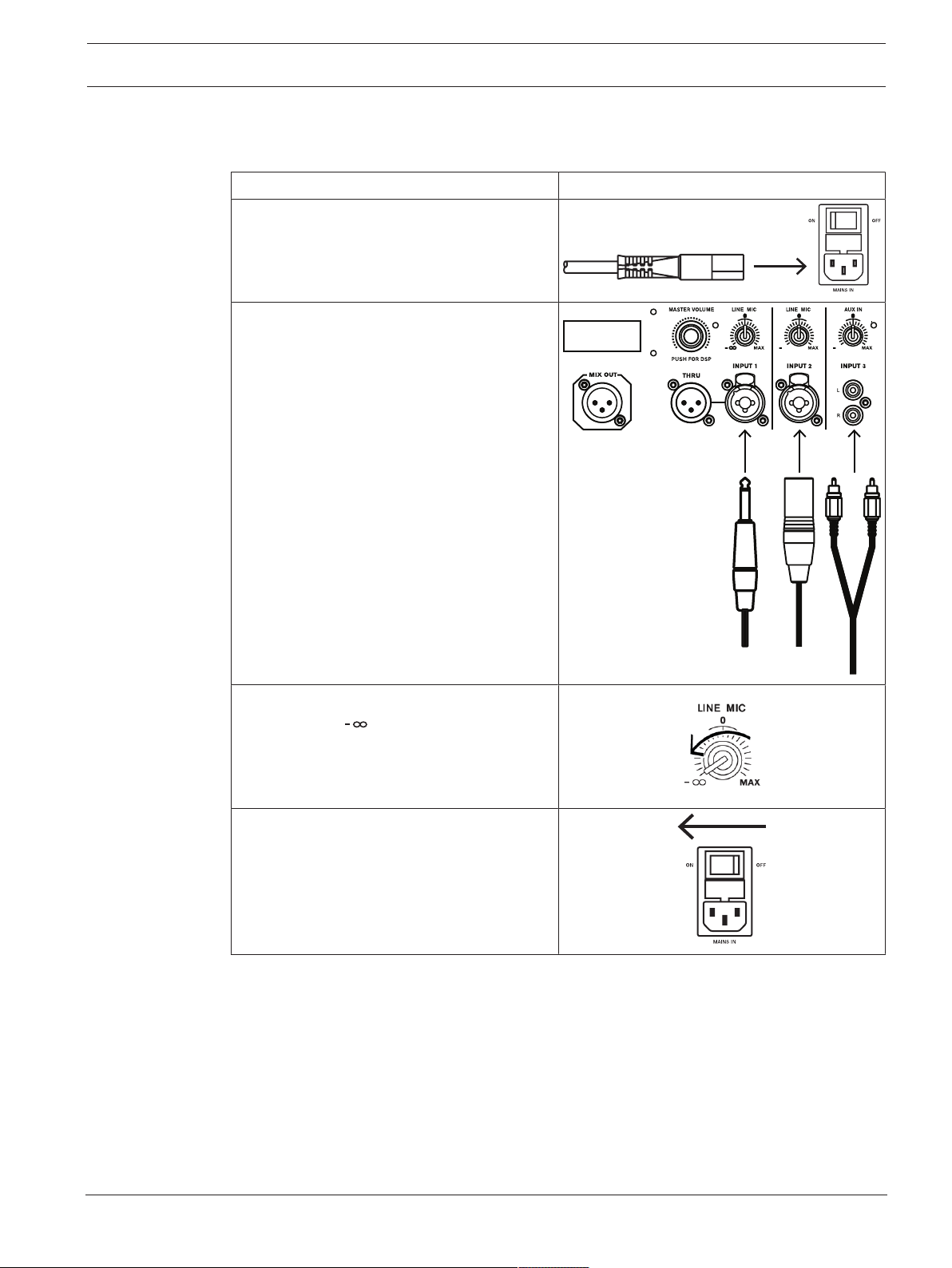
2.2 Quick setup
To quickly setup the device, do the steps that follow:
Step Illustration
1. Connect the AC power cord from a
grounded line receptacle to the MAINS
IN.
2. Connect an XLR or ¼” TRS cable from an
audio source to INPUT 1 or INPUT 2.
(Alternatively, a stereo RCA cable can be
connected to INPUT 3)
3. Adjust the associated INPUT LEVEL
knob(s) to (infinity).
4. Switch the MAINS IN power switch to
ON.
Electro-Voice Installation manual 2019-10 | v01 | F.01U.363.983
Page 10
10 en | Description PXM-12MP Powered Monitor
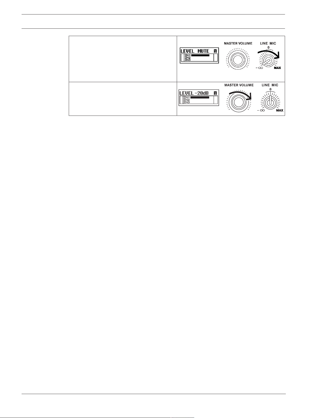
5. Increase INPUT LEVEL until desired
signal level is present on the LCD and
not indicating CLIP.
(Make sure that audio signal is present
from the source)
6. Increase MASTER VOLUME to desired
output level.
2019-10 | v01 | F.01U.363.983 Installation manual Electro-Voice
Page 11

PXM-12MP Powered Monitor Floor monitor, tripod, and pole mount operation | en 11
3 Floor monitor, tripod, and pole mount operation
3.1 Floor monitor
The PXM-12MP monitor is optimized for floor placement.
To setup the device as a monitor, do the steps that follow:
1. Make sure the surface is stable, level, and clear of debris.
2. Place the PXM-12MP on the surface.
3. Position the speaker at a distance relative to your position so that your head is on axis
with the speaker.
4. Feed the necessary cables through the cable routing hole to neatly and safely manage
cable clutter.
5. Power on the system and configure as outlined in the Quick setup section.
6. Make sure that the DSP MODE is set to MONITOR 1, MONITOR 2, or GUITARCAB.
Electro-Voice Installation manual 2019-10 | v01 | F.01U.363.983
Page 12

12 en | Floor monitor, tripod, and pole mount operation PXM-12MP Powered Monitor
!
!
3.2 Tripod
To set up the monitor on a tripod stand, do the steps that follow:
Caution!
Tripod is not evaluated for safety with this loudspeaker. Check the specifications of the
tripod stand to be certain it is capable of supporting the weight of the loudspeaker.
Caution!
We recommend that two or more persons lift and place heavier loudspeakers. Single person
lift and placement of heavier loudspeakers could cause injury.
1. Make sure the surface is stable, level, and clear of debris.
2. Place the tripod stand on the surface. The legs of the tripod should be placed as wide as
possible
3. Do not attempt to suspend more than one loudspeaker on a stand designed for a single
loudspeaker.
4. Lift the monitor with two hands and set it onto the pole.
Make sure that the pole goes into the pole cup.
5. Make sure that the DSP MODE is set to TRIPOD.
2019-10 | v01 | F.01U.363.983 Installation manual Electro-Voice
Page 13

PXM-12MP Powered Monitor Floor monitor, tripod, and pole mount operation | en 13
3.3 Pole mount with subwoofer
To set up the monitor on a subwoofer pole, do the steps that follow:
1. Place the subwoofer on a level and stable surface.
2. Put an M20 threaded pole into the combo pole cup on the top of the subwoofer.
3. Turn the M20 threaded pole clockwise to secure the pole to the subwoofer.
4. Lift the monitor with two hands and set it onto the pole.
5. Make sure that the pole goes into the pole cup of the speaker.
6. Make sure that the DSP MODE is set to TRIPOD.
7. Set the SUB parameter according to the subwoofer specifications.
Electro-Voice Installation manual 2019-10 | v01 | F.01U.363.983
Page 14

14 en | Input panel and DSP PXM-12MP Powered Monitor
PUSH FOR DSP
MAINS IN
OFF
ON
INPUT 1 INPUT 2
INPUT 3
LINE MIC
LINE MIC
AUX I N
MASTER VOLUME
MIX OU T
THRU
2
1
3
6
7 8
5
4
9
PXM-1 2MP
12” COAXIAL MONITOR
4 Input panel and DSP
4.1 Input panel controls
The input panel has a combination of controls and connectors for a wide variety of control and
configuration.
1. LCD – DSP control and monitoring interface.
2. MASTER VOLUME - Contextual rotary and push knob that is used to adjust and navigate
the DSP menu and to adjust parameters (for example Master Gain).
3. INPUT LEVEL - Rotary knob used to adjust the level of the corresponding input. The
detent 12 o’clock position represents unity level (no gain or attenuation). Rotate the knob
to the left to attenuate LINE level sources, or rotate to the right to add gain to MIC level
sources. There is an input level control for INPUT 1, INPUT 2, and INPUT 3.
4. POWER – AC switch for switching the power ON or OFF. The LCD screen lights up when
the power is turned ON, after approximately 3 seconds.
5. MIX OUT - A post-input level sum of all three input channels. This allows for the ‘mix’ to
be sent to a secondary device, such as a PA or recording device. It can be adjusted in
DSP to output a stereo signal (L+R) or an isolated RIGHT channel. This is ideal for
connecting LEFT mains to RIGHT mains in a PA configuration.
6. THRU - An output that is parallel to INPUT 1. This is not affected by the DSP of the
system. It is used to daisy-chain the signal of INPUT 1 to an external device.
7. INPUT 1, 2 - Balanced MIC/LINE XLR/TRS inputs to connect a line level signal source
(such as mixer, etc.) or a microphone. Whenever possible, balanced signal feed is always
preferable to guard against potential noise.
8. INPUT 3 - Unbalanced stereo RCA input to connect LINE-level signal sources, such as
mobile devices or media players.
9. MAINS IN - The device receives its power supply via the MAINS IN socket. Use the
included IEC power cord to connect the system to a stable, grounded power source.
Connect the device only to an electrical outlet that is capable of providing the voltage and
current outlined on the product label and system specifications.
2019-10 | v01 | F.01U.363.983 Installation manual Electro-Voice
Page 15

PXM-12MP Powered Monitor Input panel and DSP | en 15
1 2 3
4
5
6
4.2 System status
Normal
1. LEVEL – Indicates the master gain of the system in dB. The range is from mute to +10 dB,
in 1 dB increments.
2. 1 - Indicates the current recalled preset number. There are five presets available for
storing and recalling.
3. E - Indicates that the current recalled preset has updated parameters and is not saved.
4. IN1 - Indicates in meter form the magnitude of signal present on INPUT 1.
5. IN2 - Indicates in meter form the magnitude of signal present on INPUT 2.
6. IN3 - Indicates in meter form the magnitude of signal present on INPUT 3.
LIMIT
LIMIT indication is displayed when gain reduction is being applied to the signal. This allows
the loudspeaker to continue operating while preventing the amplifier and components from
exceeding their functional capability. Levels operating continuously beyond the limiter
threshold must be avoided.
PK
When PK (peak) is indicated, the INPUT signal magnitude is higher than what the amplifier can
handle and is effectively clipped (distorted). Lower the volume of the signal source and/or
lower the INPUT LEVEL by rotating the corresponding INPUT LEVEL knob counter-clockwise.
The PK status must be avoided at all times. Even momentary bursts of clipped signal can
severely damage system components.
Electro-Voice Installation manual 2019-10 | v01 | F.01U.363.983
Page 16

16 en | Input panel and DSP PXM-12MP Powered Monitor
PUSH FOR DSP
MASTER VOLUME
4.3 DSP controls
An integrated DSP control menu allows the user to select multiple DSP system settings on the
loudspeaker.
Accessing the DSP control menu
To access the DSP control menu, do the steps that follow:
1. Push the MASTER VOL knob.
2. Using the MASTER VOL knob, scroll through the menu items.
3. Push the MASTER VOL knob to select the menu item you want to modify.
4. Using the MASTER VOL knob, scroll through the parameters.
5. Push the MASTER VOL knob to confirm the selected parameter.
6. Repeat steps 2 through 5 to modify additional DSP and system settings.
7. Select EXIT to return to the home screen.
4.4 DSP control menu
The following table represents the DSP menu structure and its available parameters.
EXIT
MODE MONITOR 1
TREBLE 0 dB (Default)
MID 0 dB (Default)
MID FREQ 1000 Hz (Default)
BASS 0 dB (Default)
MONITOR 2
TRIPOD
GUITAR CAB
-10 dB to +6 dB
-10 dB to +6 dB
70 Hz - 12 kHz, sweepable
-10 dB to +6 dB
SUB OFF (Default)
80 Hz, 100 Hz, 120 Hz, 150 Hz, 200 Hz,
ELX200-12SP, ELX200-18SP, EKX-15SP,
EKX-18SP
FEEDBACK OFF (Default)
2019-10 | v01 | F.01U.363.983 Installation manual Electro-Voice
70 Hz to 10kHz
Page 17

PXM-12MP Powered Monitor Input panel and DSP | en 17
PHANTOM 1 OFF (Default)
ON
PHANTOM 2 OFF (Default)
ON
MIX OUT L+R (Default)
R
DELAY OFF (Default)
0.1m:100m:0.1m inc
Meters: 0 m to 100 m
Feet: 0 ft to 328.1 ft
LED OFF
ON (Default)
LIMIT
DISPLAY BACK
LCD DIM 30 SEC (Default)
10s to 60s
BRIGHT 5 (Default)
1 to 10
CONTRAST 5 (Default)
1 to 10
BACK
STORE EXIT, 1, 2, 3, 4, 5, EXIT
RECALL EXIT, 1, 2, 3, 4, 5, EXIT
RESET RESET ALL
SETTINGS?
NO (Default)
YES
LOCK OFF (Default)
ON
INFO PXM-12MP
<FIRMWARE VERSION>
©2019 Electro-Voice
EXIT
Electro-Voice Installation manual 2019-10 | v01 | F.01U.363.983
Page 18

18 en | Input panel and DSP PXM-12MP Powered Monitor
4.5 DSP parameter definitions
MODE - Adjusts the tuning preset applied to the output of the loudspeaker. There are four
modes available:
– MONITOR 1 - Optimized for floor monitoring purposes. (Default)
– MONITOR 2 - Secondary preset with more LF boost.
– TRIPOD - Optimized for use while installed on a tripod or subwoofer pole.
– GUITARCAB - Optimized for use as a guitar or bass guitar cabinet.
TREBLE - Used to adjust the high-frequency output of the system.
MID - Used to adjust the mid-frequency output of the system. This controls a set-Q parametric
EQ band whose center frequency is determined by the MID FREQ parameter. (Default 0dB)
MID FREQ - Adjusts the center frequency of the MID EQ band. (Default 1000Hz)
BASS - Used to adjust the low-frequency output of the system.
SUB - Enables a high-pass filter at the specified cut-off frequency. If using an Electro-Voice
subwoofer, select the appropriate model from the menu. If using other subwoofers, select the
appropriate generic high-pass frequency.
FEEDBACK - Enables and adjusts the center frequency of a narrow-Q notch filter. This can be
used in situations where there are specific frequencies that are causing the system to
feedback.
PHANTOM 1 and 2 - Activates a +15V phantom power supply on INPUT 1 and/or INPUT 2. This
is a sufficient voltage for use with most condenser microphones.
MIX OUT - Adjusts the routing and summation to the MIX OUT output. Adjust this parameter
when a stereo image is desired from two systems.
– L + R - The LEFT and RIGHT signals of INPUT 3 are summed and output to both the
loudspeaker and the MIX OUT output.
– R - The RIGHT signal of INPUT 3 is routed directly to the MIX OUT output. The
loudspeaker will only output the LEFT audio signal.
In both settings, the signals from INPUT 1 and INPUT 2 are also summed and routed to the MIX
OUT output.
DELAY - This parameter sets the amount of audio delay that will be applied before the signal
is output to the loudspeaker. This is useful for compensating the differences between
speakers at different distances from the listener. MIX OUT and THRU outputs are not affected.
2019-10 | v01 | F.01U.363.983 Installation manual Electro-Voice
Page 19

PXM-12MP Powered Monitor Input panel and DSP | en 19
LED - Enables and adjusts the functionality of the white LED located on the front grille.
– ON - The LED will always be illuminated while the loudspeaker POWER switch is set to
ON.
– OFF - The LED will remain off at all times.
– LIMIT - The LED will remain off during normal operation. Input signals above the
threshold of the internal peak limiter will momentarily illuminate the LED. This only
indicates that the limiter is active. Levels operating continuously beyond the limiter
threshold must be avoided.
DISPLAY - Submenu that contains parameters to adjust the LCD display.
– LCD DIM - When set to ON, the LCD display will automatically dim when the display is
idle for two minutes. (Default ON)
– BRIGHT - Sets the brightness of the LCD ranging from 1 to 10. (Default 5)
– CONTRAST - Adjusts the contrast between pixels on the LCD display from 1 to 10.
(Default 5)
STORE - This menu allows you to create up to five customized user settings.
To store customized user settings follow these steps:
4 From the DSP menu, scroll to STORE.
Push the MASTER VOLUME knob to select STORE.
1. Push the MASTER VOLUME knob to select 1.
2. Use the MASTER VOLUME knob to scroll through the characters.
3. Push the MASTER VOLUME knob to select the desired character.
4. Turn the MASTER VOLUME knob to move to the next character entry.
5. Use the MASTER VOLUME knob to scroll to SAVE.
6. Push the MASTER VOLUME knob to select SAVE.
7. Select EXIT to return to the home screen.
Repeat steps 3 through 8 to store additional customized user settings.
RECALL - This menu allows you retrieve up to five customized user settings.
To recall customized user settings follow these steps:
1. From the DSP menu, scroll to RECALL.
2. Push the MASTER VOL knob to select RECALL.
3. Push the MASTER VOL knob to select 1.
4. Select EXIT to return to the home screen.
RESET - This menu is used to reset the loudspeaker to original factory settings.
To reset the system to factory default settings follow these steps:
1. From the DSP menu, select RESET.
2. Select YES.
INFO - Displays the product name, firmware version, and copyright information.
EXIT - Returns the user to the HOME SCREEN.
Electro-Voice Installation manual 2019-10 | v01 | F.01U.363.983
Page 20

20 en | Recommended configurations PXM-12MP Powered Monitor
PUSH FOR DSP
MAINS IN
OFF
ON
INPUT 1 INPUT 2
INPUT 3
LINE MIC
LINE MIC
AUX IN
MASTER VOLUME
MIX OUT
THRU
PXM-12MP
12” COAXIAL MONITOR
5 Recommended configurations
5.1 Dedicated monitor
Typical application for dedicated monitoring. A main PA (EVOLVE 50 shown) sends signal to
the PXM-12MP monitor.
Notice!
The arrow direction indicates the signal path.
MODE: MONITOR 1 or MONITOR 2
SUB: OFF
Tab.5.1: DSP settings for PXM-12MP
Notice!
For EVOLVE 50 settings, please see the EVOLVE 50 User Manual
See also
– DSP control menu, page 16
2019-10 | v01 | F.01U.363.983 Installation manual Electro-Voice
Page 21

PXM-12MP Powered Monitor Recommended configurations | en 21
PUSH FOR DSP
MAINS IN
OFF
ON
INPUT 1 INPUT 2
INPUT 3
LINE MIC
LINE MIC
AUX IN
MASTER VOLUME
MIX OUT
THRU
PXM-12MP
12” COAXIAL MONITOR
PUSH FOR DSP
MAINS IN
OFF
ON
INPUT 1 INPUT 2
INPUT 3
LINE MIC
LINE MIC
AUX IN
MASTER VOLUME
MIX OUT
THRU
PXM-12MP
12” COAXIAL MONITOR
5.2 Stereo PA
A pair of monitors can be configured as a conventional stereo PA with some tripods and basic
DSP adjustments.
MODE: <TRIPOD>
SUB: <OFF>
MIX OUT: <R>
Tab.5.2: DSP settings for PXM-12MP
See also
– DSP control menu, page 16
Electro-Voice Installation manual 2019-10 | v01 | F.01U.363.983
Page 22

22 en | Recommended configurations PXM-12MP Powered Monitor
PUSH FOR DSP
MAINS IN
OFF
ON
INPUT 1 INPUT 2
INPUT 3
LINE MIC
LINE MIC AUX I N
MASTER VOLUME
MIX OUT
THRU
PXM-12MP
12” COAXIAL MONITOR
RRLL
QuickSmartDSP MONITOR|QuickSmartDSP MONITOR|
AUX INAUX IN
OUTPUTOUTPUT
MASTER VOLMASTER VOL INPUT 1INPUT1
IN
PUT2INPUT2
PUSH FO R D SP
ELX200ELX200
PUSH FOR DSP
MAINS IN
OFF
ON
INPUT 1 INPUT 2
INPUT 3
LINE MIC
LINE MIC AUX I N
MASTER VOLUME
MIX OUT
THRU
PXM-12MP
12” COAXIAL MONITOR
RRLL
QuickSmartDSP MONITOR|QuickSmartDSP MONITOR|
AUX INAUX IN
OUTPUTOUTPUT
MASTER VOLMASTER VOL INPUT 1INPUT1
IN
PUT2INPUT2
PUSH FO R D SP
ELX200ELX200
5.3 Main PA with subwoofer
The addition of subwoofers allows for improved system LF response as well as more overall
headroom.
MODE: TRIPOD
SUB: ELX200-18SP
Tab.5.3: DSP Settings for PXM-12MP with ELX200-18SP subwoofer for stacked
Notice!
For ELX200 settings, please see the ELX User Manual.
See also
– DSP control menu, page 16
2019-10 | v01 | F.01U.363.983 Installation manual Electro-Voice
Page 23

PXM-12MP Powered Monitor Troubleshooting | en 23
6 Troubleshooting
Problem Possible Cause(s) Action
1. No sound Amplifier Verify all the electronics are on, the signal routing is
correct, the source is active; the volume is turned up,
etc.
Correct/repair/replace as necessary. If there is still no
sound, then the problem may be wiring.
Wiring Verify you have connected the correct cables to the
amplifier. Play something at a low level through the
amplifier. Connect a test loudspeaker in parallel with the
malfunctioning line. If the sound level is gone or is very
weak, the line has a short in it (possibly a severe scrape,
pinch, or a missed connection). Using the test
loudspeaker, move down the line and test each
connection/junction until you find the problem and
correct it. Observe proper polarity.
2. Poor Low-
Frequency
Response
3. Intermittent output
such as cracking or
distortion
4. Constant noise
such as buzzing,
hissing or humming
5. No sound produced
with microphone
connected to INPUT
1 or INPUT 2
With SUB menu
cross-over frequency
activated
Faulty connection Check all connections at amplifier and loudspeakers to
Defective source or
other electronic
device
Poor system
grounding or ground
loop
Input gain knob is
not in the MIC
position
Microphone requires
phantom power.
Input gain knob is
not in the MIC
position
If no subwoofers are used with the system, select the
OFF position.
ensure they are all clean and tight. If the problem
persists, check the wiring. See problem 1.
If noise is present, but no program material is playing,
evaluate each component as necessary to isolate the
problem. Most likely there is a break in the signal path.
Check and correct the system grounding, as required.
Slowly increase the input gain knob level to engage the
microphone pre-amp.
Switch PHANTOM 1 or PHANTOM 2 to ON in the menu.
See DSP control menu, page 16.
Slowly increase the input gain knob level to engage the
microphone pre-amp.
6. Sound is distorted
front LED is OFF,
LCD screen LIMIT is
ON
Electro-Voice Installation manual 2019-10 | v01 | F.01U.363.983
Excessive input level Reduce the input level or loudspeaker level knobs to
prevent limit.
Incorrect gain
structure or source
input (mixing
console/preamp) is
overdriven
Verify level controls of the source are properly structured
by using the VU meter indicator on the LCD screen. If the
VU meter bar is solid or the system indicates LIMIT, the
input or source level is too high.
Page 24

24 en | Troubleshooting PXM-12MP Powered Monitor
Problem Possible Cause(s) Action
7. Microphone
produces acoustic
Incorrect gain
structure
feedback when
input level is
amplified
Microphone position
is too close to the
front of the
loudspeaker
8. DSP menu is locked The Menu Lock
function has been
turned on. A lock
symbol displays on
the LCD screen.
Reduce the microphone levels at the mixing console or
input source. If the microphone is connected directly to
the speaker, reduce the input level on the speaker.
Positioning the microphone close to the sound source
increases gain-before-feedback. See problem 6.
Adjust FEEDBACK frequency until the feedback
frequency is found. See DSP control menu, page 16.
Press and hold the MASTER VOL knob for 5 seconds.
2019-10 | v01 | F.01U.363.983 Installation manual Electro-Voice
Page 25

PXM-12MP Powered Monitor Technical data | en 25
7 Technical data
Frequency response (-3 dB): 64 Hz - 20 kHz
Frequency range (-10 dB): 53 Hz - 20 kHz
Monitor Angle: 55°
Maximum SPL: 129 dB
Coverage (H x V): 90˚ x 90˚
Amplifier Rating: 700 W
LF Channel Rating: 500 W
HF Channel Rating: 200 W
Crossover frequency: 1.6 kHz
Transducer: CXCA2128-1NA 12” / 1.75” 2-way coaxial
Connectors: 2x XLR/TRS combo input
1x Stereo RCA input
1x XLR THRU input
1x XLR MIXOUT output
Enclosure: 15 mm Plywood
Grille: Steel with black powder coat
Color: Black
Dimensions (H x W x D):
mm (in)
Net weight: 13.5 kg (29.8 lb)
Shipping weight: 15.6 kg (34.3 lb)
Power consumption: 100 - 240 V AC, 50 - 60 Hz, 0.8 - 0.5 A
334 mm x 409 mm x 484 mm
(13.1 in x 16.1 in x 19.0 in)
Electro-Voice Installation manual 2019-10 | v01 | F.01U.363.983
Page 26

26 en | Technical data PXM-12MP Powered Monitor
20 50 100 200 500 1k 2k 5k 10k 20k
Frequency (Hz)
60
65
70
75
80
85
90
95
100
Sound Pressure Level (dB)
Frequency Response
Tripod Mode, Full Space
Monitor 1 Preset, Half Space
Monitor 2 Preset, Half Space
Guitar Cab Preset, Half Space
2019-10 | v01 | F.01U.363.983 Installation manual Electro-Voice
Page 27

PXM-12MP Powered Monitor Technical data | en 27
Vertical
Horizontal
10 degrees / Division
3dB / Division
0dB, -6dB, and -24dB Bold
V0°
H0°
100Hz
V0°
H0°
125Hz
V0°
H0°
160Hz
V0°
H0°
200Hz
V0°
H0°
250Hz
V0°
H0°
315Hz
V0°
H0°
400Hz
V0°
H0°
500Hz
V0°
H0°
630Hz
7.1 Off Axis Response
Electro-Voice Installation manual 2019-10 | v01 | F.01U.363.983
Page 28

28 en | Technical data PXM-12MP Powered Monitor
Vertical
Horizontal
10 degrees / Division
3dB / Division
0dB, -6dB, and -24dB Bold
V0°
H0°
800Hz
V0°
H0°
1kHz
V0°
H0°
1.25kHz
V0°
H0°
1.6kHz
V0°
H0°
2kHz
V0°
H0°
2.5kHz
V0°
H0°
3.15kHz
V0°
H0°
4kHz
V0°
H0°
5kHz
V0°
H0°
6.3kHz
V0°
H0°
8kHz
V0°
H0°
10kHz
2019-10 | v01 | F.01U.363.983 Installation manual Electro-Voice
Page 29

PXM-12MP Powered Monitor Technical data | en 29
482,2 mm
(18.9”)
436 mm
(17.2”)
23º
35º
126,8 mm
(5”)
469,5 mm
(18.48”)
71,1 mm
(2.8”)
409 mm
(16.1”)
333,4 mm
(13.1”)
7.2 Dimensions
Electro-Voice Installation manual 2019-10 | v01 | F.01U.363.983
Page 30

30 | Technical data PXM-12MP Powered Monitor
2019-10 | v01 | F.01U.363.983 Installation manual Electro-Voice
Page 31

Page 32

Bosch Sicherheitssysteme GmbH
Robert-Bosch-Ring 5
85630 Grasbrunn
Germany
www.boschsecurity.com
© Bosch Sicherheitssysteme GmbH, 2019
Bosch Security Systems, Inc
12000 Portland Avenue South
Burnsville MN 55337
USA
www.electrovoice.com
© Bosch Security Systems, Inc., 2019
 Loading...