

Electro-Voice PWS-4, PWS-6, PWS-C Owner's Manual
OWNER’S MANUAL
BEDIENUNGSANLEITUNG
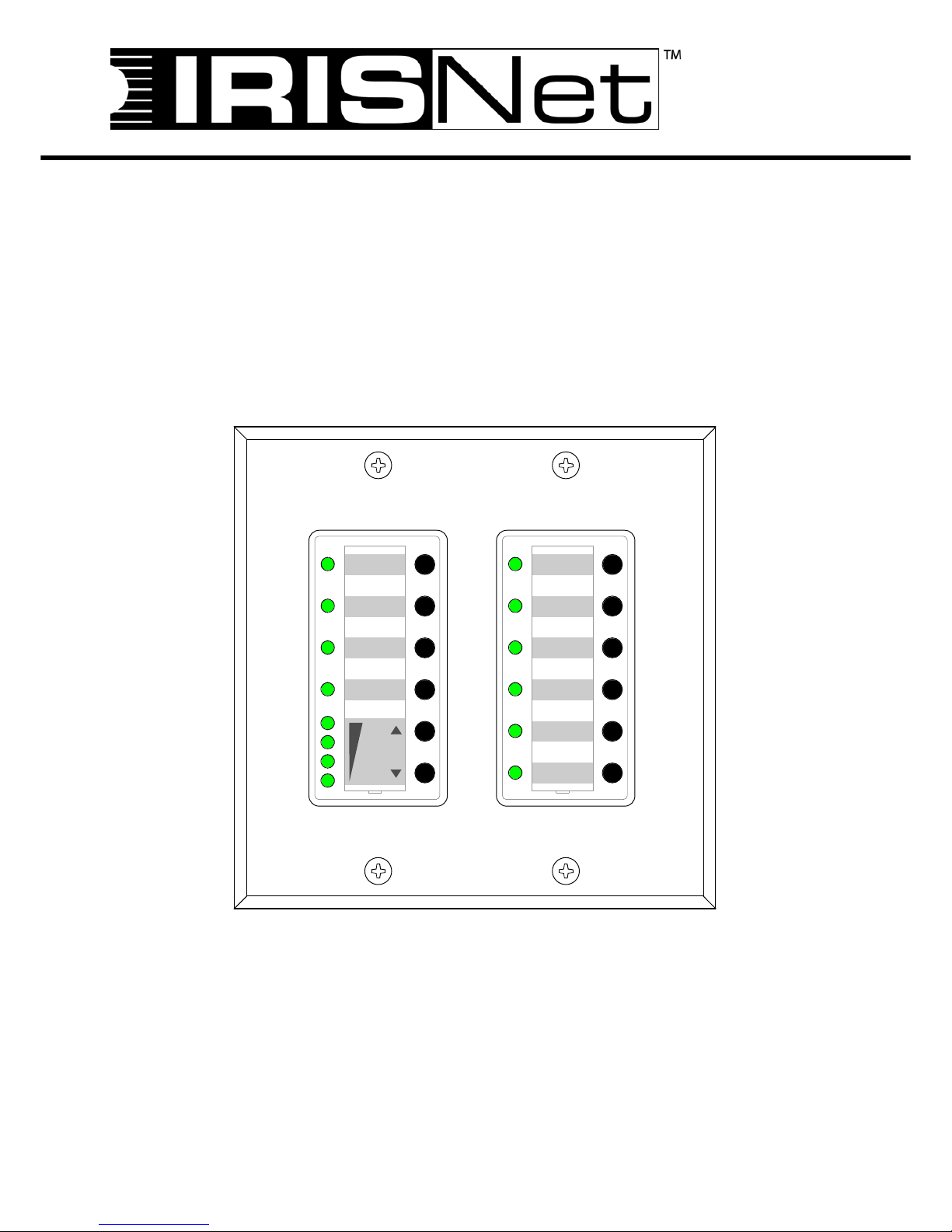
PWS
PROGRAMMABLE WALL STATION
VOLUME
CHANNEL 1
CHANNEL 2
CHANNEL 3
CHANNEL 4
CHANNEL 1
CHANNEL 2
CHANNEL 3
CHANNEL 4
CHANNEL 5
CHANNEL 6

PROGRAMMABLE WALL STATION
2 Bedienungsanleitung
CONTENTS
Introduction . . . . . . . . . . . . . . . . . . . . . . . . . . . . . . . . . . . . . . . . . . . . . . . . . . . . . . . . . . . . . . . . . 4
Overview . . . . . . . . . . . . . . . . . . . . . . . . . . . . . . . . . . . . . . . . . . . . . . . . . . . . . . . . . . . . . . 4
Applications . . . . . . . . . . . . . . . . . . . . . . . . . . . . . . . . . . . . . . . . . . . . . . . . . . . . . . . . . . . . 5
IRIS-Net™ . . . . . . . . . . . . . . . . . . . . . . . . . . . . . . . . . . . . . . . . . . . . . . . . . . . . . . . . . . . . . 5
CAN-Bus coupler PWS-C . . . . . . . . . . . . . . . . . . . . . . . . . . . . . . . . . . . . . . . . . . . . . . . . . . . . . . 6
PWS Front Unit PWS-4/PWS-6 . . . . . . . . . . . . . . . . . . . . . . . . . . . . . . . . . . . . . . . . . . . . . . . . . 7
PWS-4 . . . . . . . . . . . . . . . . . . . . . . . . . . . . . . . . . . . . . . . . . . . . . . . . . . . . . . . . . . . . . . . . 7
PWS-6 . . . . . . . . . . . . . . . . . . . . . . . . . . . . . . . . . . . . . . . . . . . . . . . . . . . . . . . . . . . . . . . . 8
Mounting and Configuration . . . . . . . . . . . . . . . . . . . . . . . . . . . . . . . . . . . . . . . . . . . . . . . . 8
Initial Operation . . . . . . . . . . . . . . . . . . . . . . . . . . . . . . . . . . . . . . . . . . . . . . . . . . . . . . . . . . . . . 10
Hardware Configuration . . . . . . . . . . . . . . . . . . . . . . . . . . . . . . . . . . . . . . . . . . . . . . . . . . . 11
CAN-Status-LED . . . . . . . . . . . . . . . . . . . . . . . . . . . . . . . . . . . . . . . . . . . . . . . . . . . . . . . . 15
Connection . . . . . . . . . . . . . . . . . . . . . . . . . . . . . . . . . . . . . . . . . . . . . . . . . . . . . . . . . . . . . 15
Find Function . . . . . . . . . . . . . . . . . . . . . . . . . . . . . . . . . . . . . . . . . . . . . . . . . . . . . . . . . . . 17
Diagnostic Mode . . . . . . . . . . . . . . . . . . . . . . . . . . . . . . . . . . . . . . . . . . . . . . . . . . . . . . . . . 17
Automatic Configuration . . . . . . . . . . . . . . . . . . . . . . . . . . . . . . . . . . . . . . . . . . . . . . . . . . . 18
Firmware Update . . . . . . . . . . . . . . . . . . . . . . . . . . . . . . . . . . . . . . . . . . . . . . . . . . . . . . . . 18
CAN-Bus Principles . . . . . . . . . . . . . . . . . . . . . . . . . . . . . . . . . . . . . . . . . . . . . . . . . . . . . . . . . . 19
INHALT
Einführung . . . . . . . . . . . . . . . . . . . . . . . . . . . . . . . . . . . . . . . . . . . . . . . . . . . . . . . . . . . . . . . . . 23
Überblick . . . . . . . . . . . . . . . . . . . . . . . . . . . . . . . . . . . . . . . . . . . . . . . . . . . . . . . . . . . . . . 23
Anwendungsmöglichkeiten . . . . . . . . . . . . . . . . . . . . . . . . . . . . . . . . . . . . . . . . . . . . . . . . . 24
IRIS-Net™ . . . . . . . . . . . . . . . . . . . . . . . . . . . . . . . . . . . . . . . . . . . . . . . . . . . . . . . . . . . . . 24
CAN-Bus-Koppler PWS-C . . . . . . . . . . . . . . . . . . . . . . . . . . . . . . . . . . . . . . . . . . . . . . . . . . . . . 25
PWS-Frontbedieneinheiten PWS-4/PWS-6 . . . . . . . . . . . . . . . . . . . . . . . . . . . . . . . . . . . . . . . . 26
PWS-4 . . . . . . . . . . . . . . . . . . . . . . . . . . . . . . . . . . . . . . . . . . . . . . . . . . . . . . . . . . . . . . . . 26
PWS-6 . . . . . . . . . . . . . . . . . . . . . . . . . . . . . . . . . . . . . . . . . . . . . . . . . . . . . . . . . . . . . . . . 27
Montage und Konfiguration . . . . . . . . . . . . . . . . . . . . . . . . . . . . . . . . . . . . . . . . . . . . . . . . 27
Inbetriebnahme . . . . . . . . . . . . . . . . . . . . . . . . . . . . . . . . . . . . . . . . . . . . . . . . . . . . . . . . . . . . . . 29
Hardware-Konfiguration . . . . . . . . . . . . . . . . . . . . . . . . . . . . . . . . . . . . . . . . . . . . . . . . . . . 30
CAN-Status-LED . . . . . . . . . . . . . . . . . . . . . . . . . . . . . . . . . . . . . . . . . . . . . . . . . . . . . . . . 34
Anschluss . . . . . . . . . . . . . . . . . . . . . . . . . . . . . . . . . . . . . . . . . . . . . . . . . . . . . . . . . . . . . . 34
Find-Funktion . . . . . . . . . . . . . . . . . . . . . . . . . . . . . . . . . . . . . . . . . . . . . . . . . . . . . . . . . . . 36
Diagnosemodus . . . . . . . . . . . . . . . . . . . . . . . . . . . . . . . . . . . . . . . . . . . . . . . . . . . . . . . . . 36
Automatische Konfiguration . . . . . . . . . . . . . . . . . . . . . . . . . . . . . . . . . . . . . . . . . . . . . . . . 37
Firmware-Update . . . . . . . . . . . . . . . . . . . . . . . . . . . . . . . . . . . . . . . . . . . . . . . . . . . . . . . . 37
CAN-Bus-Grundlagen . . . . . . . . . . . . . . . . . . . . . . . . . . . . . . . . . . . . . . . . . . . . . . . . . . . . . . . . 38
APPENDIX
Specification . . . . . . . . . . . . . . . . . . . . . . . . . . . . . . . . . . . . . . . . . . . . . . . . . . . . . . . . . . . . . . . . 41
Block Diagram . . . . . . . . . . . . . . . . . . . . . . . . . . . . . . . . . . . . . . . . . . . . . . . . . . . . . . . . . . 42
Dimensions . . . . . . . . . . . . . . . . . . . . . . . . . . . . . . . . . . . . . . . . . . . . . . . . . . . . . . . . . . . . . 42
Declaration of Conformity . . . . . . . . . . . . . . . . . . . . . . . . . . . . . . . . . . . . . . . . . . . . . . . . . . 44
Setting CAN-Address via DIP-Switch ADDRESS . . . . . . . . . . . . . . . . . . . . . . . . . . . . . . . 45
PROGRAMMABLE WALL STATION
Bedienungsanleitung 3
IMPORTANT SAFETY INSTRUCTIONS
1. Read these instructions.
2. Keep these instructions.
3. Heed all warnings.
4. Follow all instructions.
5. Do not use this apparatus near water.
6. Clean only with a dry cloth.
7. Do not block any ventilation openings. Install in accordance with the manufacture’s instructions.
8. Do not install near heat sources such as radiators, heat registers, stoves, or other app ara tus (includin g am p lifiers) that produce heat.
9. Do not defeat the safety purpose of the polarized or the grounding-type plug . A polarized plug has two blades w ith one wider than the other.
A grounding type plug has two blades and a third grounding prong. The wide blade o r the third pron g are provided for your safety. If the
provided plug does not fit into your outlet, consult an electrician for replacement of the obsolete outlet.
10. Protect the power cord from being walked on or pinched pa rticularly at plugs, convenience rece pt a cles, and the point w he re they exit from
the apparatus.
11. Only use attachments/accessories specified by the manufacturer.
12. Use only with the cart, tripod, bracket, or table specified by the manufacturer, or sold with the apparatus. When a cart is used, use caution
when moving the cart/apparatus combination to avoid injury from tip-over.
13. Unplug this apparatus during lightning storms or when unused for a long period of time .
14. Refer all servicing to qualified service personnel. Servicing is required when the apparatus has bee n damaged in any way, such a s pow e rsupply cord or plug is damaged, liquid has been spilled or object s have fallen into the app aratus, the ap paratu s has been expo sed to rain or
moisture, does not operate normally, or has been dropped.
15. Do not expose this equipment to dripping or splashing and ensure that no objects filled with liquids, such as vases, are placed on the
equipment.
16. To completely disconnect this equipment from the AC Mains, disconnect the power supply cord plug from the AC rece pt a cle.
17. The mains plug of the power supply cord shall remain readily operable.
IMPORTANT SERVICE INSTRUCTIONS
CAUTION: These servicing instructions are for use by qualified personnel only. T o reduce the risk of electric shock, do not
perform any servicing other than that contained in the Operating Instructions unless you are qualified to do so.
Refer all servicing to qualified service personnel.
1. Security regulations as stated in the EN 60065 (VDE 0860 / IEC 65) and the CSA E65 - 94 have to be obeyed when
servicing the appliance.
2. Use of a mains separator transformer is mandatory during maintenance while the appliance is opened, needs to be
operated and is connected to the mains.
3. Switch off the power before retrofitting any extensions, changing the mains voltage or the output voltage.
4. The minimum distance between parts carrying mains voltage and any accessible metal piece (metal enclosure),
respectively between the mains poles has to be 3 mm and needs to be minded at all times. The minimum distance between
parts carrying mains voltage and any switches or breakers that are not connected to the mains (secondary parts) has to be
6 mm and needs to be minded at all times.
5. Replacing special components that are marked in the circuit diagram using the security symbol (Note) is only permissible
when using original parts.
6. Altering the circuitry without prior consent or advice is not legitimate.
7. Any work security regulations that are applicable at the locations where the appliance is being serviced have to be strictly
obeyed. This applies also to any regulations about the work place itself.
8. All instructions concerning the handling of MOS-circuits have to be observed.
The lightning flash with arrowhead symbol, within
an equilateral triangle is intended to alert the user
to the presence of uninsulated “dangerous
voltage“ within the product’s enclosure that may
be of sufficent magnitude to constitute a risk of
electric shock to persons.
The exclamation point within an equilateral triangle is intended to alert the user to the presence
of important operating and maintenance (servicing) instructions in the literature accompanying
the appliance.
Management of WEEE (waste electrical and electronic equipment) (applicable in Member States of the European Union and other European countries with individual national policies on the management of WEEE) The
symbol on the product or on its packaging indicates that this product may not be treated as regular household
waste, but has to be disposed through returning it at a Telex dealer.
NOTE: SAFETY COMPONENT (MUST BE REPLACED BY ORIGINAL PART)
PROGRAMMABLE WALL STATION
4 Owner’s manual
1 Introduction
1.1 Overview
The programmable wall stations of the modular PWS system (Programmable Wall Station) allow local
control and operation of various devices and systems via CAN-Bus. A programmable wall station lets you
control several funct ions, f or exampl e: sour ce sele ction, volume con trol, muting or powerin g on/off devices.
In addition, using a suitable central control unit allows controlling a variety of facilities in a building (light,
heating/air condition, etc.).
The minimum configuration for the operation of a programmable wall station consists of:
• A front unit (e.g. PWS-4)
• A CAN coupler (PWS-C)
• A software configuration created in IRIS-Net™ and transferred to the programmable wall station via
CAN-Bus
• A CAN-Bus master unit to be controlled (e.g. Electro-Voice NetMax N8000)
The front units represent the part of the programmable wall station for the user to access, i.e. the user
interface. Different front units with differing numbers and types of controls or indicators are available. A
number of front units grouped in a single programmable wall station have to be connected in series, with
up to three front units connected to a single bus coupler.
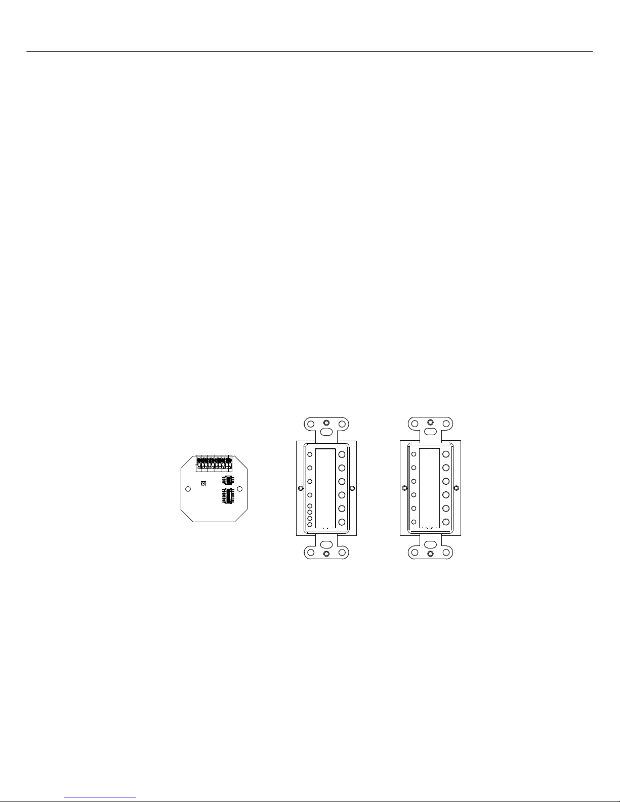
The CAN-Bus coupler PWS-C provides connectio n between front units and the CAN-Bus. T he maximum
number of units connected to a CAN-Bus (e.g. PWS-C, Remote Amplifier, etc.) depends on employed
central control unit. Please consult the corresponding manuals.
CAN-Bus coupler PWS-C Front unit PWS-4 Front unit PWS-6
PROGRAMMABLE WALL STATION
Owner’s manual 5
1.2 Applications
PWS panels can be included in any audio installation, for example:
• Stadiums and theaters
• Cruise ships
• Multi-purpose halls
• Schools and Universities
• Government agencies
• Airports
• Theme parks
• Exhibition centers and museums
• Conference centers and hotels
1.3 IRIS-Net™
When shipped, programmable wall stations have not been configured yet. The progr amming of control and
indication functions is done using the PC software IRIS-Net™ (Intelligent Remote & Integrated
Supervision). After transferring the custom configuration to the programmable wall station, the PWS
becomes functional and it is able to control the system components (N8000, remote control amplifiers,
etc.) independent of a PC or IRIS-Net™. Simultaneous Control from a PWS and IRIS-Net™ is possible.
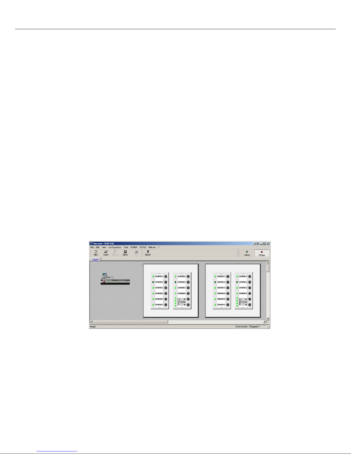
The IRIS-Net™ help files contain all the information on configuration, operation and monitoring of all
programmable wall station functions. The following illustration shows an example of a PWS system in
IRIS-Net™.
Illustration 1.1: PWS system in IRIS-Net
PROGRAMMABLE WALL STATION
6 Owner’s manual
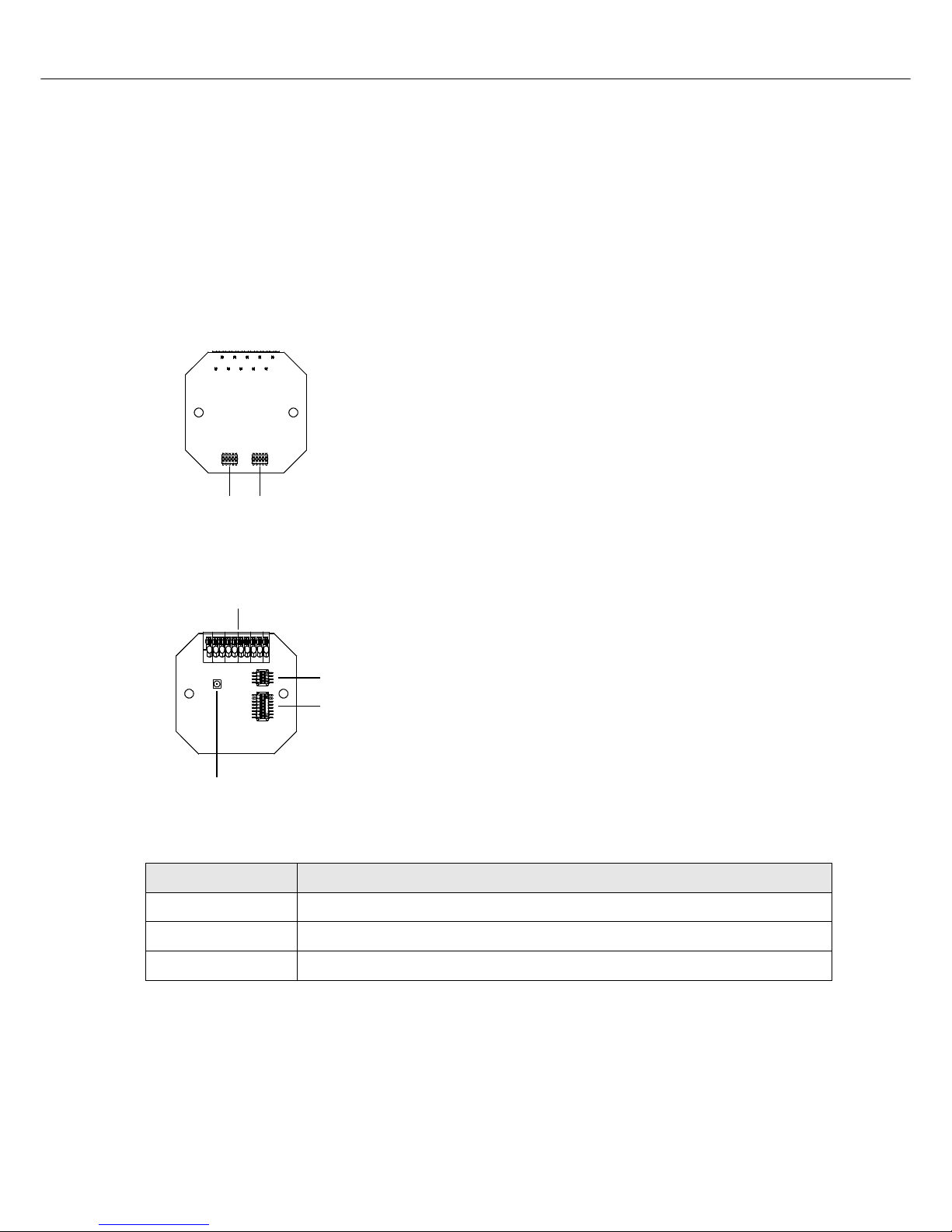
2 CAN-Bus coupler PWS-C
The CAN-Bus coupler PWS-C provides connection between front units (e.g. PWS-4) and the CAN-Bus.
The CAN-Bus coupler registers the activation of controls on the connected front units and sends the
needed information via CAN-Bus to the devices to be controlled, but also directs info rmatio n received from
the CAN-Bus to the control units for indication. The CAN-Bus coupler offers connectors for CAN-Bus and
power supply as well as DIP switches for the CAN-Bus configuration (baud rate, bus termination and CANBus address). The CAN-Bus coupler PWS-C is suitable for European and US-type flush-mount boxes.
Front view:
Rear view:
Default settings:
1 Connector for the front unit
2 Connector for future extensions
1 DIP switch TERM/BAUD for setting baud rate and termination of
the CAN-Bus (see page 11)
2 DIP switch ADDRESS for setting the CAN-address (see page 14)
3 CAN Status-LED for monitoring communication on the CAN-Bus
4 T erminal for CAN-Bus and supply voltage (see page 15)
Parameter Value
Baud rate PROG mode (10 kbaud, changeable via IRIS-Net™)
Termination off
CAN-Bus address 00 (C AN-Bus off, Stand-a lone)
12
1
2
3
4

PROGRAMMABLE WALL STATION
Owner’s manual 7
3 PWS Front Unit PWS-4/PWS-6
PWS-4 and PWS-6 are front units of the modular PWS system. They are meant for installation in a UStype wall box. Typical applications are: source selection, volume control and preset-switching.
All controls and indicators of the front units are freely configurable via IRIS-Net™. Individually labeling the
controls and indicators according to their assign functions is possible after removing the label field cover.
The front units PWS-4 or PWS-6 are being used in combination with the CAN-Bus coupler PWS-C. Up to
three front units can be operated on a single PWS-C.
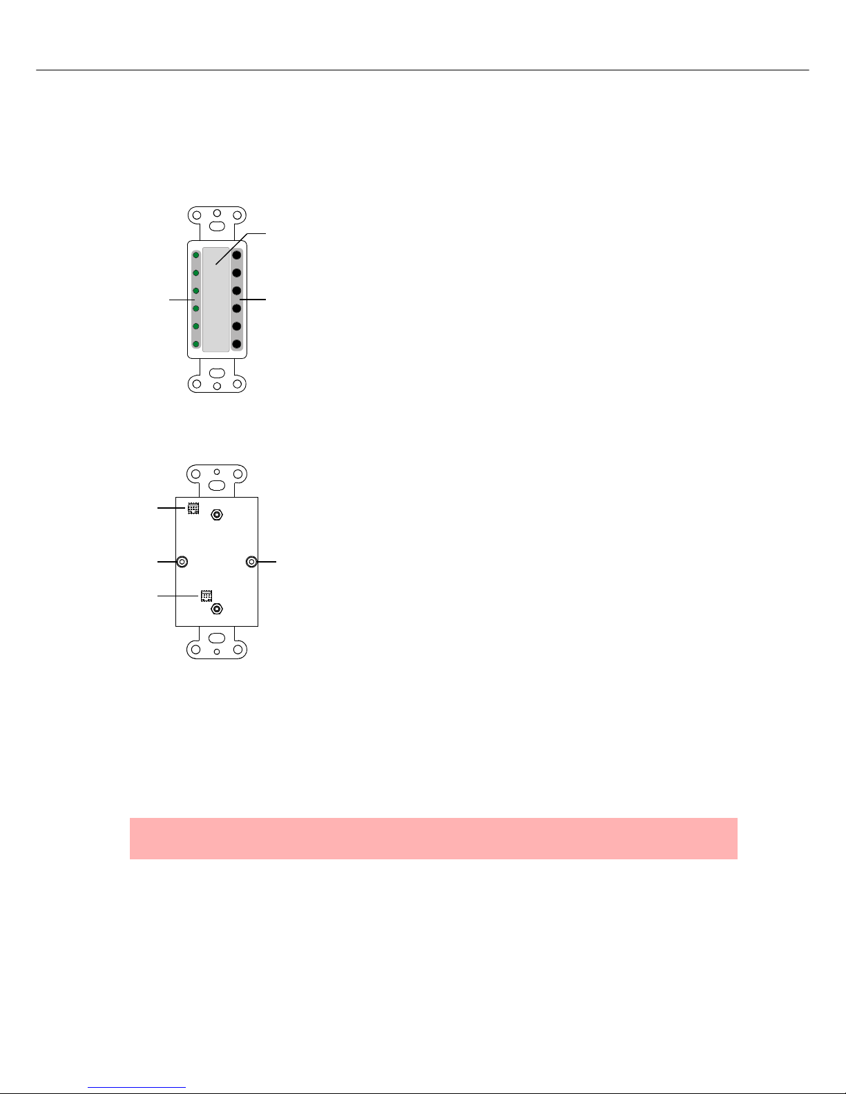
3.1 PWS-4
The PWS-4 has in total 6 buttons, with the upper four buttons having a separate Status-LED, each. The
two lower buttons can be used as Up/Down buttons. The set parameter status is signaled via LED-chain.
Front view:
Rear view:
1 St atus-LEDs for the function keys (3)
2 Label field
3 Freely configurable function keys
4 Up/Down buttons
5 LED-chain indicates a parameter’s value that has been changed
using the Up/Down buttons (4)
1 Connector for the PWS-C or input socket (IN) for connecting the
PWS-4 to the previous front unit in the chain
2 Output socket (OUT) for connecting the PWS-4 to the next front
unit in the chain
3 Mechanical lock for the PWS-C plus cover
CHANNEL 2
CHANNEL 3
CHANNEL 4
3
5
1
4
CHANNEL 1
VOLUME
2
1
3
3
2
OUT
IN
PROGRAMMABLE WALL STATION
8 Owner’s manual
3.2 PWS-6
The PWS-6 has 6 buttons with Status-LEDs.
Front view:
Rear view:
3.3 Mounting and Configuration
The front units PWS-4 or PWS-6 are connected with two screws to the CAN-Bus coupler PWS-C (see
page 11). All front units of a programmable wall station have to be connected in series. Front units are
daisy chained by connecting the output socket (OUT) of a front unit to the input socket (IN) of the next unit
in the chain.
1 Freely configurable function keys
2 Label field
3 Status-LEDs for the function keys (1)
1 Connector for the PWS-C or input socket (IN) for connecting the
PWS-6 to the previous front unit in the chain
2 Output socket (OUT) for connecting the PWS-6 to the next front
unit in the chain
3 Mechanical lock for the PWS-C plus cover
NOTE:
Connecting sockets of the same type (IN to IN or OUT to OUT) is not permissible.
CHANNEL 2
CHANNEL 3
CHANNEL 4
CHANNEL 5
CHANNEL 6
CHANNEL 1
1
3
2
1
3
3
2
OUT
IN
PROGRAMMABLE WALL STATION
Owner’s manual 9
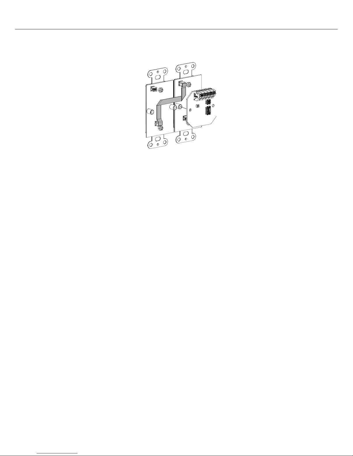
Only the supplied connection cables should be used for proper operation. The following illustration shows
the connection of two front units of a programmable wall station.
Other than connections, no physical configuration of the front units is required, as the assignment of
functions and other configurations are perfor med in IRIS-Net™. Adjacent front units have to be installed
and connected in the following order: from left to right and from top to bottom.
Abbildung 3.1: Connecting two front units of a programmable wall station
PROGRAMMABLE WALL STATION
10 Owner’s manual
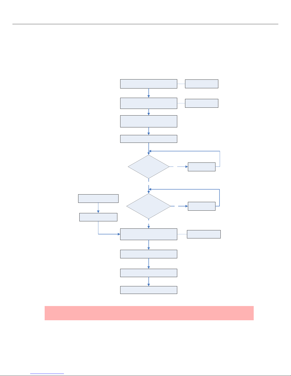
4 Initial Operation
When shipped, PWS panels have not been configured yet. The following illustration provides an overview
of the entire procedure of installing and configuring a PWS for the first time. Please also refer to the
descriptions of other connecte d devices in the corresponding chap ters as well as the IRIS-Net™ on-line
help feature.
NOTE:
The system automatically recognizes and configures spare units (see page 18)
Power-on the central control unit and
power supply of the programmable wall
station
According to IRIS-Net, is
the CAN-Bus okay?
The PWS system is ready for operation
Transfer the configuration to the
programmable wall station
Yes
Perform a test: test all user functions
Label the frontal control unit, replace the
cover(s)
Connect all cables, configure DIP-switches
(baud rate, termination, CAN-address)
See IRIS-Net on-line help
See chapter “Hardware
Configuration”
Localize faults and
fix them
No
Screw CAN-Bus coupler and a front unit
together, connect additional front units
See chapter PWS-C,
PWS-4, etc.
Connect the control unit to PC/IRIS-Net
Have all units been
detected that are connected
to the CAN-Bus?
Yes
Localize faults and
fix them
No
Configure the programmable
wall station in IRIS-Net
Check the configuration in
IRIS-Net (“Offline Test”)
PROGRAMMABLE WALL STATION
Owner’s manual 11
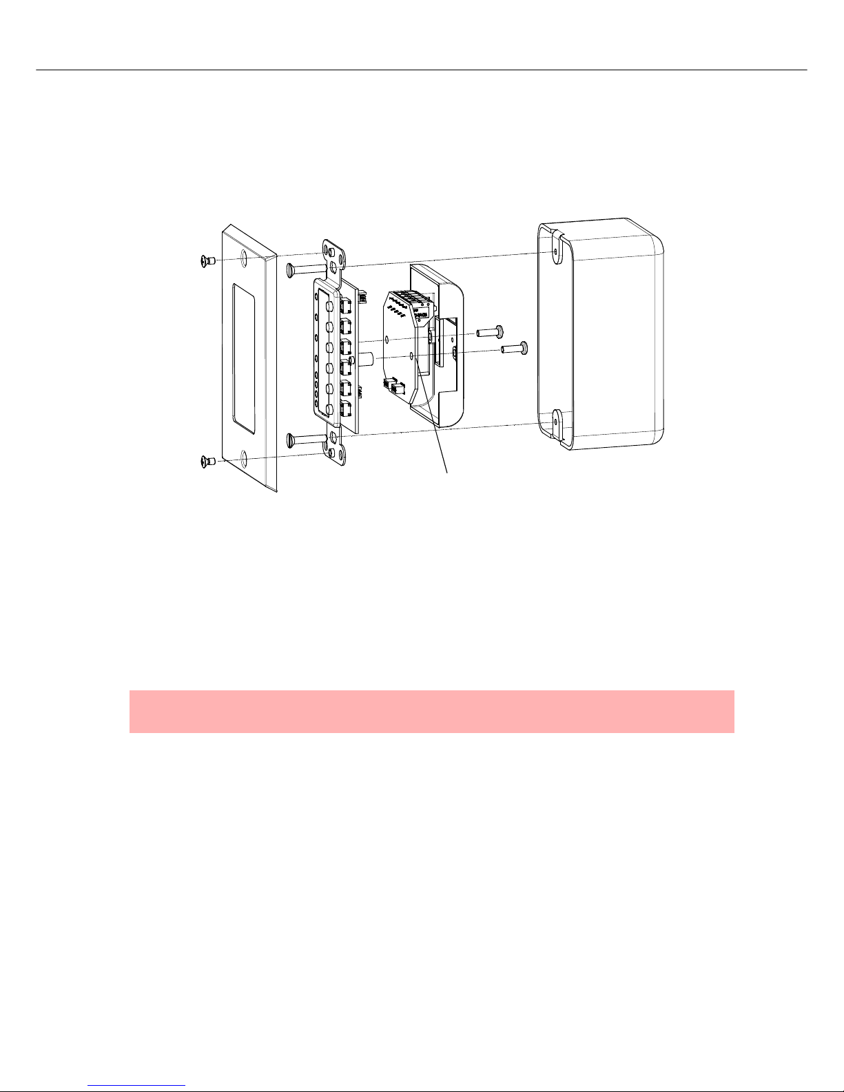
Mounting a Programmable wall station in a US Single Gang Wall Box
For mounting a programmable wall station you have to lock the PWS- C and a front un it of a pr ogrammabl e
wall station together using two screws. Using the supplied connection cables, connect additional front
units. Please also refer to this manual’s corresponding chapters describing the connection procedure for
the front units being used.
4.1 Hardware Configuration
The DIP-switches of the PWS-C allow setting the baud rate (page 11), termination (page 13), and CANaddress (page 14). An overview of default DIP-switch settings is provided on page 6.
Baud Rate
Determination of a suitable baud rate
The maximum allowable baud rate of the CAN-Bus is indirect proportion to the bus length. For smaller
networks, baud rates of up to 500 kbit/s are possible. Large networks require a lower baud rate (down to
the minimum baud rate of 10 kbit/s). The follow ing table illustrates the relationship between baud rate and
bus length, i.e. network dimensions. Generally, bus lengths over 1000 meters should always employ CANrepeaters.
CAUTION:
All devices on the CAN-Bus have to be set to the same baud rate.
USE SPACERS IF
NO PWS-C IS USED
PROGRAMMABLE WALL STATION
12 Owner’s manual
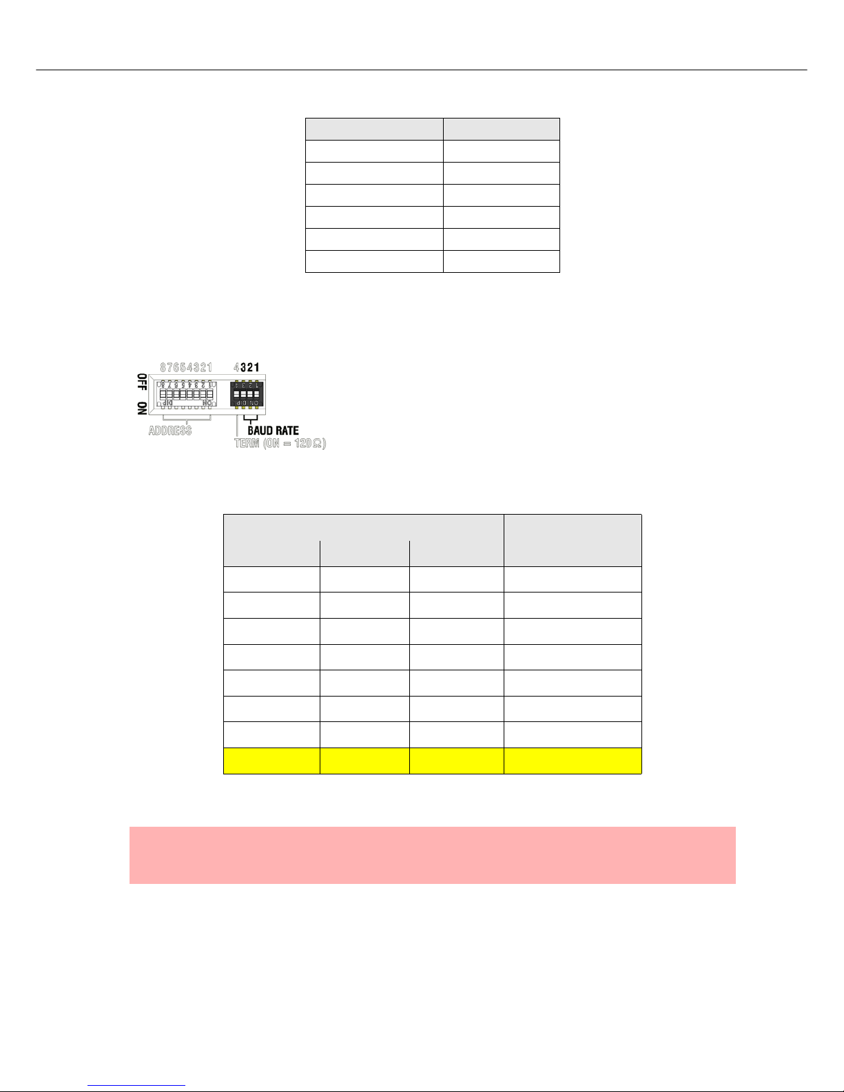
Setting the Baud Rate
Setting the bus coupler’s baud rate is possible by using switches 1, 2
and 3 of the TERM/BAUD DIP-switches. Potential baud rates and
corresponding switch settings a re shown in the following table. Only
when set to PROG Mode, it is possible to change the programmable
wall station’s baud rate via IRIS-Net™. With all other switch settings,
the previously selected value for the baud rate is maintained.
A dark shaded field in the table marks the default value when shipped. In PROG mode, the default data
rate is 10 kbit/s.
Baud rate (in kbit/s) Bus-length (in m)
500 100
250 250
125 500
62,5 1000
20 2500
10 5000
Table 4.1: Baud rate and Bus-length in CAN-networks
DIP switch TERM/BAUD
Baud rate (in kbit/s)
Switch 3 Switch 2 Switch 1
OFF OFF OFF 10
OFF OFF ON 20
OFF ON OFF 62.5
OFF ON ON 125
ON OFF OFF 250
ON OFF ON 500
ON ON OFF not available
ON ON ON PROG mode
Table 4.2: Setting the baud rate
NOTE:
Changing a previously set fixed baud rate is not possible via IRIS-Net™. The PWS must be in
PROG mode to allow the changing of the baud rate via IRIS-Net™.
PROGRAMMABLE WALL STATION
Owner’s manual 13
Setting a default baud rate in PROG mode
As shown in the above table, setting a fixed baud rate is possib le when conn ecting a PWS- C to an al rea dy
existing CAN-Bus. When connecting a PWS-C in PROG mode, setting the baud rate directly on the PWSC is possible by following these instructions:
1. Activate the power supply of the PWS-C
2. Set the desired baud rate using the DIP-switch TERM/BAUD (see page 12)
3. Wait until the new baud rate is adopted, which is signaled by a dimmed CAN-Status-LED.
4. PROG mode settings with DIP-switch TERM/BAUD (see page 12)
The PWS-C can now be taken into operation with the baud rate set under step 2.
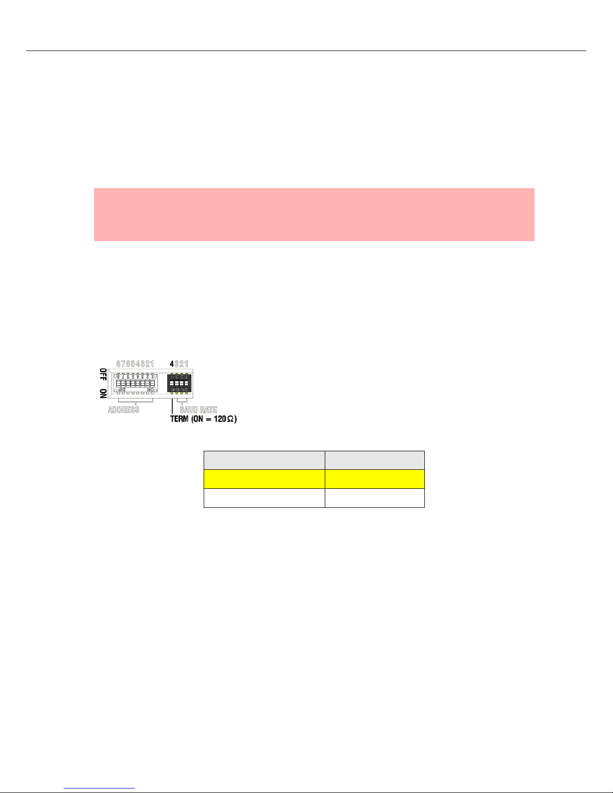
Termination
Both ends of a CAN-Bus have to be terminated using a 120 Ω
terminator. Missing or erroneous termination can result in
malfunction. Contact 4 of DIP-switch 1 allows activating the PWS-C’s
integrated terminator (see the following table).
A dark shaded field in the table marks the default setting when
shipped.
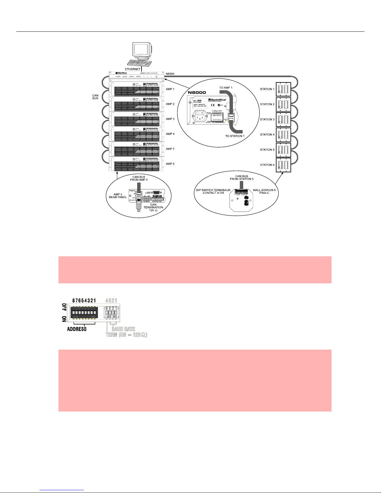
The following illustration provides an example of a NetMax-Systems, with Remote Power Amps and
programmable wall station being connected via CAN-Bus. Both ends of the CAN-Bus are terminated using
terminators.
NOTE:
The CAN-Status-LED light for 3 seconds whenever changes are applied to the DIP-switches with
the power supply being activated. The new setting is adopted only when the CAN-Status-LED is
dimmed.
DIP switch 1, Contact 4 Termination
OFF open
ON closed (120 Ω)
Table 4.3: CAN-Bus Termination
PROGRAMMABLE WALL STATION
14 Owner’s manual
CAN address
Every programmable wall station has to have a unique CAN address
to be identified on the CAN-Bus. The usable address range is: 1 (01
hex) up to 250 (FA hex). The PWS-C’s ADDRESS DIP switch (see
page 6) allows specifying the CAN address by setting a two-digit
hexadecimal number. A table of possible CAN addresses and
corresponding DIP-switch settings is provided on page 45.
The default CAN address when shipped is 0 (00 hex).
CAUTION:
T o prevent network fault s, each CAN address may exist once only throughout a system.
Conflicts on the network would be the result.
NOTES:
Various programmable wall stations of a system can be easily configured when their
CAN addresses are in consecutive order.
A programmable wall station is disconnected from the CAN-Bus when its CAN address
has been set to 0.
If the setting of the DIP-switch is changed, the CAN status LED lights up for 3 seconds.
The new setting becomes effective when the CAN status LED is dimmed.
PROGRAMMABLE WALL STATION
Owner’s manual 15
4.2 CAN-Status-LED
The entries in following table are arranged after falling priority, i.e. if two conditions arise at the same time,
only the upper condition in the table is indicated.
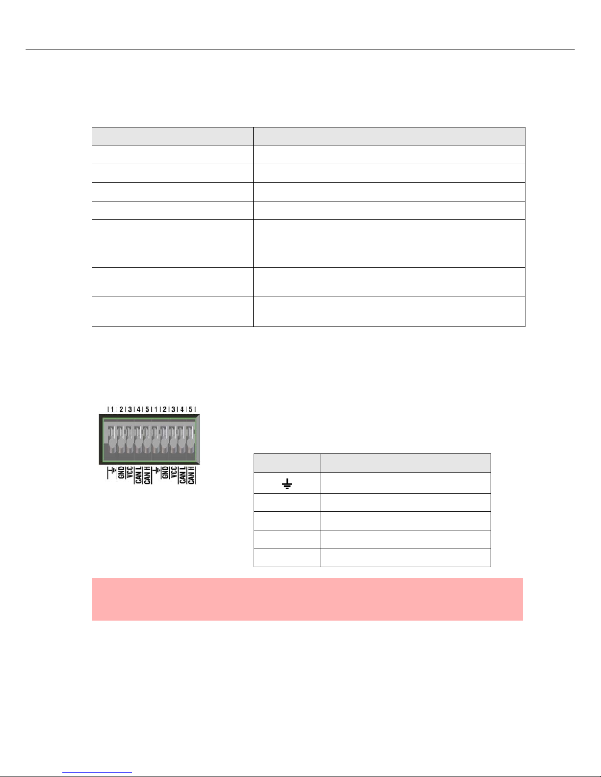
4.3 Connection
The PWS-C has a 10-pole terminal clip for the connection of CAN-Bus
signal transmission and power supply. Using cable with diameters
between 0.5 mm and 0.8 mm (20 -24 AWG) is possible. For further
information, please refer to the chapter “cable specifications” on page 20.
CAN-Status-LED Description
Off No power supply
Continuously lit Firmware Update / Configuration in progress
Continuously lit for 3 seconds Changes applied to the DIP-switch setting are adopted
Blinks fast (50 ms ON, 50 ms OFF) Find function active
Activation for 100 ms Sending data
Blinks every second twice for 100 msError state (Hardware fault, wrong configuration, no connection
to a CAN unit, missing/wrong panel)
Blinks rhythmically every 3 seconds
for 100 ms
The PWS-C is separated from the CAN-Bus via software (CAN
address 00)
Blinks rhythmically every second for
100 ms
Normal operation, no data transfer
Table 4.4: CAN-Status-LED - modes of indication
Connection Description
Cable shield
GND Operating voltage (-) / CAN_GND
VCC Operating voltage (+)
CAN L CAN_L
CAN H CAN_H
NOTE:
Power supply ground and CAN-Bus ground are not galvanically separated. The
potential difference on the GND-line may not exceed 5 volts.
 Loading...