

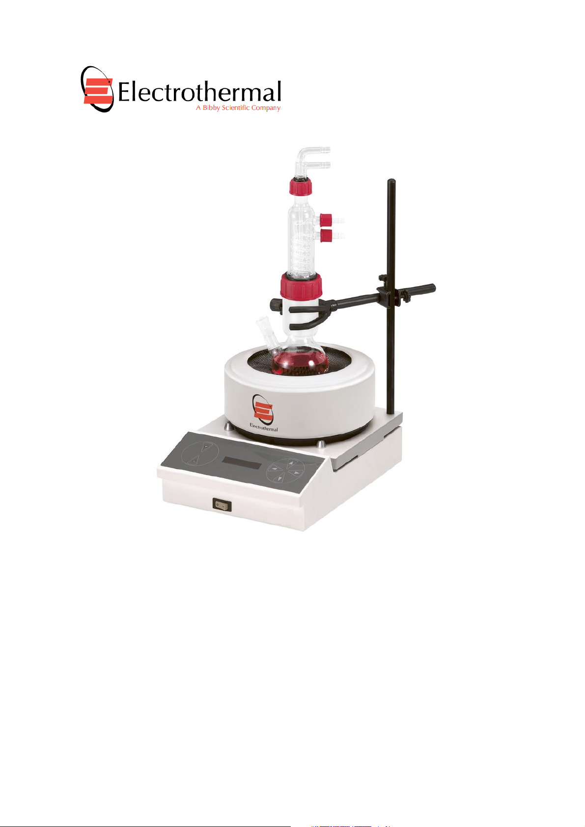
Digi-Mantle – A Reaction Station with Interchangeable Mantles.
OMCA0250, OMCA0500, OMCA1000.
INSTRUCTION BOOK.
Page 1 of 28. Digi-Mantle M7754 issue 14.3

Please take your time to read this Instructions book in order to understand the safe and
Contents.
Section 1.
Page
3
Section 2.
Page
4
Section 3.
Page
5
Section 4.
Page
7
Section 5.
Page
8
Section 6.
Page
9
Section 7.
Page
10
Section
8.
Page
21
Section 9.
Page
23
Section 10.
Page
25
Section 11.
Page
26
Section 12.
Page
28
Appendix ‘A’
Page
27
Bibby Scientific Limited.
correct use of your new Bibby Scientific product.
It is recommended the Responsible Body for use of this equipment reads this
Instruction book and ensures the user(s) are suitably trained in its operation.
Introduction
Symbols and using this instruction book.
Safety Information.
Unpack and Contents.
Installation.
Environmental Protection.
Product Operation.
Technical Specification.
Maintenance
Parts and Accessories
Customer Support
EC Declaration of Conformity.
Decontamination Certificate
© The copyright of this instruction book is the property of Bibby Scientific Limited. This instruction book is supplied
by Bibby Scientific Limited on the express understanding that it is to be used solely for the purpose for which it is
supplied. It may not be copied, used or disclosed to others in whole or part for any purpose except as authorised
in writing by Bibby Scientific Limited. Bibby Scientific Limited reserves the right to alter, change or modify this
document without prior notification.
In the interest of continued development Bibby Scientific Limited reserve the right to alter or modify
the design and /or assembly process of their products without prior notification.
This product is manufactured in Great Britian by Electrothermal, part of the Bibby Scientific Group of
companies.
Beacon Road,
Stone,
Staffordshire ST15 0SA,
Great Britain.
Tel: +44(0)1785 812121
Fax: +44(0)1785 810405
Page 2 of 28. Digi-Mantle M7754 issue 14.3

1. INTRODUCTION
1.1. Your Digi-Mantle has been designed to provide a comprehensive answer to heating and
stirring fluids in various vessel formats. This product is modular in design allowing for
complete interchange ability between mantles of various sizes. With its ‘easy to read / easy
to operate’ revolutionary CTC (Capacitance Touch Control) panel, setting the required
temperature and stir speed takes only seconds.
1.2. Heating is controlled by a modern ‘state of the art’ micro processor, which displays the
heat setting as a percentage of the total power. When the temperature probe is fitted, the
heating is controlled via the temperature feed back circuit and the actual temperature is
displayed. All new dry blocks come with an inbuilt temperature sensor. This allows the true
block temperature to be viewed at all times. When using a probe and dry block with in built
sensor, the temperature displayed is that as measured by the probe.
1.3. An ‘all new’ digital controller and motor arrangement allow for accurate, low speed stirring
control. Uniform stirring is provided via a motorised rotating magnet assembly positioned to
provide maximum magnetic flux linkage to rotate the stirrer bars in each reaction vessel.
Page 3 of 28 Digi-Mantle M7754 issue 14.4
2. SYMBOLS AND USING THIS INSTRUCTION BOOK.
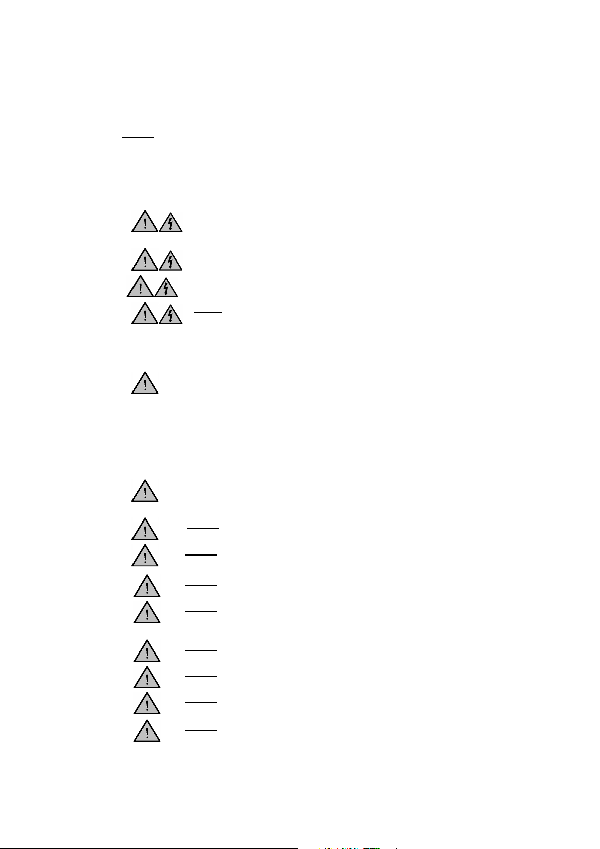
2.1. Throughout this Instruction book the following symbols are shown to identify conditions
which pose a hazard to the user, or to identify actions that should be observed. These
symbols are also shown on the product, or its packaging. When a symbol is shown next to
a paragraph or statement it is recommended the user takes particular note of that
instruction in order to prevent damage to the equipment or to prevent injury to one’s self or
other people.
To prevent injury or equipment damage it is the manufacturer’s recommendation
that all persons using this equipment are suitably trained before use.
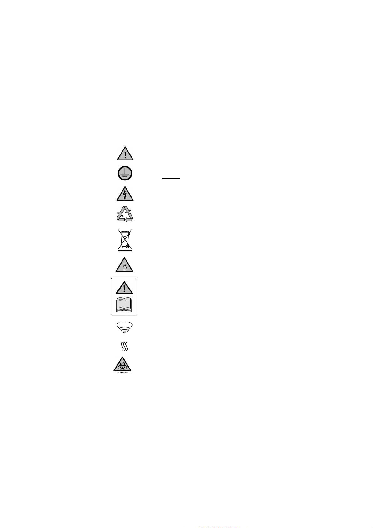
2.2. Symbols Defined.
Caution, risk of danger. See note or adjacent
symbol.
Protective conductor terminal to be earthed.
Do Not loosen or disconnect.
Caution / risk of electric shock
Recyclable Packing Material
Do not dispose of product in normal domestic
waste.
Caution. Hot surface.
Refer to Operator Instructions book.
Stirring Facility On / Off
Heating Facility On / Off
Bio Chemical Hazard. Caution required. Will require
decontamination.
Page 4 of 28 Digi-Mantle M7754 issue 14.3
DO NOT
Never
Do not
Do not
Do not
Do not
Do not
Do not
Do not
Do not
3. SAFETY INFORMATION.
This product has been designed for safe operation when used as detailed in accordance
with the Manufactures instructions.
NOTE: Failure to use this equipment in accordance with the manufactures operating
instructions may compromise your basic safety protection afforded by the equipment and
may invalidate the warranty / guarantee. The warranty / guarantee dose not cover damaged
caused by faulty installation or misuse of the equipment.
3.1. Prevention of Fire and Electric Shock.
To prevent a risk of fire or electric shock,
product case without authorisation. Only qualified Service personnel
3.2. General Safe Operating Practice.
should attempt to repair this product
Replace fuses only with the type as listed in section, Parts and
Accessories (See fuse type and rating)
Ensure the Mains Power Supply conforms to rating found on the
data plate located on the underside of each item of this equipment.
Operate this equipment with out connection to earth /
ground. Ensure the mains supply voltage is correctly earthed /
grounded in accordance with current area legislation.
Always follow good laboratory practice when using this
equipment. Give due recognition to your company’s safety and
legislative health & safety procedures and all associated legislation
applicable to your areas of operation. Check laboratory procedures
for substances being heated and ensure all hazards (e.g. explosion,
implosion or the release of toxic or flammable gases) that might
arise have been suitably addressed before proceeding. When
heating certain substances the liberation of hazardous gases may
require the use of a fume cupboard or other means of extraction.
Ensure equipment is used on a clean, dry, non-combustible, solid
work surface with at least 300mm suitable clearance all around
from other equipment.
position the product so that it is difficult to disconnect from
the mains supply.
touch the heating element or any glass vessel whilst in use.
immerse unit in water or fluids.
spill substances onto the mantle. If spillage does occur,
disconnect unit from mains supply and follow instructions as
detailed in Section ‘Maintenance’.
cover the mantle whilst in use.
leave equipment switched on without a charged flask(s).
install or remove the mantle from the control unit whilst
power is applied to the controller.
thermally insulate the exposed upper section of the
vessel(s), as the insulation used may obstruct the convection
cooling airways around the rim of the cartridge enclosure and cause
the mantle to overheat.
open your
Page 5 of 28 Digi-Mantle M7754 issue 14.4

It is not recommended to leave any heating apparatus unattended
Do not
during operation.
Only use Original Equipment manufactures spares and
accessories. Ref Section 10.
This equipment employs the use of rotating magnets. Keep all
metal objects and magnetic data devises (credit cards, door /
security passes) away from the stirrer unit.
The equipment is not spark, flame or explosion proof and has not
been designed for use in hazardous areas in terms of BSEN 6007914:1997. Keep flammable, low flash point substances away from
the apparatus.
operate or handle any part of this product with wet hands.
Keep the Mains cord and moulded IEC plug and lead set cable
away from the heating surface.
Page 6 of 28 Digi-Mantle M7754 issue 14.3
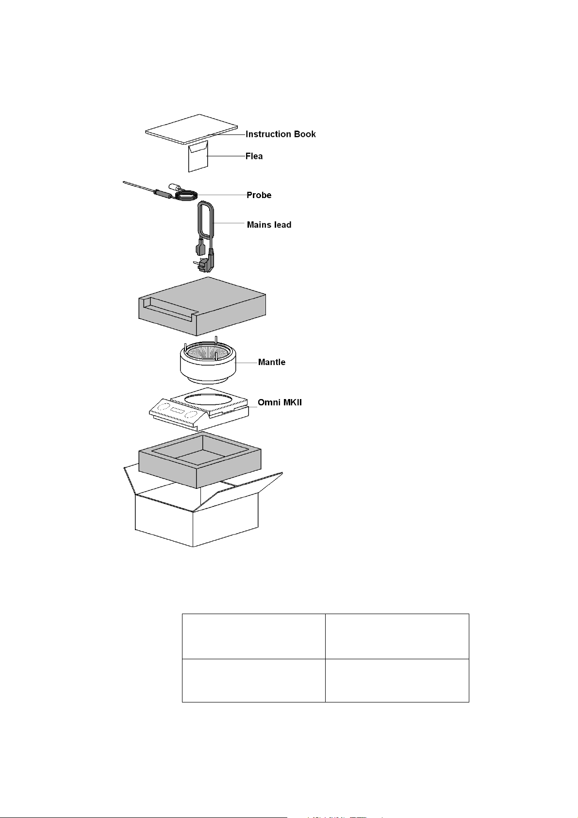
1x Digi controller with inbuilt stir
4. UNPACK AND CONTENTS.
4.1. OMCA0250, OMCA0250X1, OMCA0500, OMCA0500X1, OMCA1000, OMCA1000X1,
1x Instruction Book
1 x Flea Stir bar
(0250 mantle). OR
(0500 mantle). OR
(1000 mantle).
1x Probe
1x Mains lead and moulded IEC
plug and lead set (UK)
1x Mains lead and moulded IEC
plug and lead set (Europe)
1x Mains lead and moulded IEC
plug and lead set (USA)
1x Mantle
(0250ml). OR
(0500ml). OR
(1000ml).
Page 7 of 28 Digi-Mantle M7754 issue 14.4
For your future reference
Controller Serial Number
please record your products
Serial and Model numbers.
Mantle Serial Number

=
Blue
or
White
=
Neutral
Brown
or
Black
=
Live / line hot.
5. INSTALLATION.
5.1. Electrical safety and installation.
5.1.1. This equipment is designed for safe use under the following conditions:-
• Indoor use.
• Altitude up to 2000 meters.
• Temperatures between 5°C and 40°C.
• Maximum relative humidity 80% for temperatures up to 31°C decreasing
linearly to 50% relative humidity at 40°C.
• Mains input supply voltage fluctuations up to ± 10% of the nominal voltage.
• Transient over-voltages typically present on the mains supply.
• Applicable rated pollution degree 2.
5.1.2.
This equipment must be earthed / grounded to a fixed earth / grounded mains
socket outlet. The mains supply is to be earthed / grounded in accordance with
current legislation.
5.1.3. Ensure only the correct rated mains input fuses are fitted. (Where applicable
ensure the correct Mains cord and moulded IEC plug and lead set cable fuse if fitted).
See Technical Information Section 8 of this document.
5.1.4. Check the input voltage on the product data label of each Digi-Mantle item. Ensure
the rating conforms to your local supply.
5.1.5. This product should be connected to a mains supply source which incorporates an
RCD or GFCI device that has a tripping current of 30mA or less. The RCD or GFCI
residual Current Device cuts off power to the equipment immediately it detects a
current leakage fault. For example, cutting off the power when there is an accidental
liquid spillage in a mantle protected with an earth (ground) screen.
5.1.6. The unit is supplied with a Mains cord and moulded plug set cable wired as follows.
Green / Yellow
or
Green
Earth / Ground
When using with a new mantle:
Observation: the surface of the heating element of a mantle cartridge will upon receipt look
slightly discoloured. This discolouration is normal and occurs at the factory during testing
when the mantle is first heated up.
Page 8 of 28 Digi-Mantle M7754 issue 14.3
6. ENVIRONMENTAL PROTECTION.
6.1. Maximum consideration has been given to environmental issues within the design and
manufacturing process without compromising end product performance and value.
6.2. Packaging materials have been selected such that they may be sorted for
recycling.
6.3. At the end of your product and accessories life, it must not be discarded as domestic
waste. Ref: EU Directive 2002/96/EC on Waste Electrical and Electronic Equipment
Directive (WEEE). Please contact your distributor / supplier for further information. For end
users outside of the EU consult applicable regulations.
6.4. This product should only be dismantled for recycling by an authorised recycling company.
This product and accessories must be accompanied by a completed
Decontamination Certificate prior to any disposal. Copies of the Certificate are
available from your distributor of Bibby Scientific products, or you may copy and
enlarge from ‘Appendix A’ of this instruction book.
Bibby Scientific’s Electrothermal branded product range is registered with the Environment Agency under the name of as Electrothermal
Engineering Limited as being a producer of WEEE (Waste Electronic and Electrical Equipment) through b2b Compliance, an authorised
waste collection compliance scheme.
Page 9 of 28 Digi-Mantle M7754 issue 14.4

7. PRODUCT OPERATION.
7.1. Overview.
Your Digi-Mantle has been designed for easy operation. The illustrations show a
detailed layout of your Digi-Mantle control unit.
Figure 7 – 1
1 Magnetic Stir Hub.
2 Stir activation key
3 Heater activation key
4 LCD Display
5 Menu selection keys
Figure 7 - 2
6 On / Off power switch
Page 10 of 28 Digi-Mantle M7754 issue 14.3

Figure 7 - 3
7 External probe socket.
8 Data plate label.
9 Mantle cartridge control plug
10 Mantle cartridge power supply socket
11 Vertical Rod clamp fastening bracket
12 Mains Input IEC socket.
13 Earth test point
14 Fuses.
Figure 7 - 4
Typical front screen display.
7.2. Support Rod. (optional).
The Digi-Mantle incorporates a vertical rod support bracket. The rod is to be fastened
into the bracket. Glass arrangements are to be secured in conjunction with
appropriate clamp and flask support when using a Mantle.
7.3. Fitting a Mantle
7.3.1. Fitting a Mantle cartridge is achieved by aligning the 9 pin plug of the Mantle
cartridge with the 9 pin socket.
Page 11 of 28 Digi-Mantle M7754 issue 14.4

7.3.2. Carefully lower the Mantle cartridge into the control unit ensuring the tabs on the
controller align with the grooves in the base of the dry block or mantel ensuring
positive engagement.
7.3.3. If required, insert the external sample temperature probe plug into the external
probe socket.
WARNING.
Care should be exercised when handling a Mantle.
WARNING.
Ensure the mains electricity supply is turned off and disconnected before fitting
a Mantle.
7.4. Power on and Front Screen menu.
7.4.1. Connect the Mains cord and moulded IEC plug and lead set cable supplied with the
Digi-Mantle into the mains power inlet socket (see figure 7-3, item12). Press the On /
Off switch (see figure 7-2 item 6) to the on position.
7.4.2. The LCD display will go through a warm and self check routine that will take a few
seconds during which the Digi-Mantle Software revision will be displayed for 5
seconds before conformation. Upon completion of the routine the Digi-Mantle LCD will
then display the type of heating apparatus being used. (See figure 7-4).
Note: All function selections and settings are made using the menu keys. The keys
are indicated using
Press the right hand menu key
<^>
symbols in the LCD display.
>
to confirm correct module.
Figure 7-5
Note: The profile for 500ml is the same as the 1000ml. When using the 500ml
mantle 1000ml will be shown on the display. Please note this is not a fault of
the unit or the mantle. The 250ml mantle will display 250ml Mantle.
If the Error message ‘Module Missing’ is displayed (see figure 7-6) turn off the
Digi-Mantle unit. Insert a Mantle cartridge or ensure the existing module is correctly
seated.
Figure 7-6
• the main screen menu will look like the illustration seen in Figure 7-7.
Note: The e character next to the temperature display when external probe is
connected.
Figure 7-7.
Page 12 of 28 Digi-Mantle M7754 issue 14.3

7.5. Stir speed setting and activation.
From the main display screen menu press the > key to enter the ‘Stir speed’ setting
screen. (See figure 7-8).
Note: the Stir speed displayed is that of the last setting made by the user.
Press the > key to enter the stir speed selection screen. (See figure 7-9).
Press the ^ key to make the 100’s value selection. Press the v key if you wish to
reduce the selected stir speed value.
Press the > key to go into the 10’s selection screen (See figure 7-10).
Figure 7-8.
Figure 7-9.
Figure 7-10.
Press the ^ key to make the 10’s value selection. Press the v key if you wish to
reduce the selected stir speed value.
Press the > key to return to the front screen menu.
OR…….
If 10 seconds elapse without a key being pressed the display is to return to the
main display menu.
Note: There is no facility for setting the units stir speed value.
To start the stirring process press the stir key marked with the symbol
To stop the stirring process press the stir key once more.
Note. To show stirring is in operation the stir symbol will remain illuminated. The
stir speed shown on the LCD is the true speed of stir. Not the setting.
Page 13 of 28 Digi-Mantle M7754 issue 14.4

7.6. Heat setting and activation.
7.6.1. Setting the temperature when using a Mantle cartridge without internal
sensor.
From the main display menu screen press the < key to go into the ‘Heat setting’
screen. (See figure 7-11).
Note: The default setting will always display 00%. Previous power settings are not
retained.
Press the > key to go into set power selection screen. (See figure 6-12).
Press the ^ key to make the % power selection. Press the v key if you wish to
reduce the power selection.
Note: The power settings are made in increments of 5°C. The power selection
range is from 0 to 100%.
Figure 7-11.
Figure 7-12.
Press the > key to return to the front screen menu.
OR…….
If 10 seconds elapse without a key being pressed the display is to return to the
main display menu.
To start the heating process press the heating key marked with the symbol .
To stop the heating process, press the heating key once more.
Note. To show heating is in operation the heat symbol will remain illuminated. The
power percentage shown on the LCD is that of the setting.
7.6.2. Setting the temperature when using Mantle cartridge using the external
probe.
Note: With the external probe attached an e symbol will appear in the LCD next to
the temperature reading indicating the connection of the external probe (See Figure
7-9). The Temperature reading displayed is that read by the probe.
The external probe is to be placed in the sample solution. Heating your sample is
now controlled via the external probe.
From the main display menu screen press the < key to go into the ‘Temperature
setting’ screen. (See figure 7-13).
Figure 7-13.
Note: the Stir temperature displayed is that of the last setting made by the user.
Page 14 of 28 Digi-Mantle M7754 issue 14.3

Press the > key to go into temperature selection screen. (See figure 7-14).
Figure 7-14.
Press the ^ key to make the 100’s temperature value selection. Press the v key if
you wish to reduce the selected temperature value.
Press the > key to go into the 10’s temperature selection screen (See figure 7-15).
Figure 7-15.
Press the ^ key to make the 10’s temperature value selection. Press the v key if
you wish to reduce the selected temperature value.
Press the > key to go into the units temperature selection screen (See figure 7-16).
Figure 7-16.
Press the ^ key to make the units temperature value selection. Press the v key if
you wish to reduce the selected temperature value.
Press the > key to return to the front screen menu.
OR…….
If 10 seconds elapse without a key being pressed the display is to return to the
main display menu.
To start the heating process press the heating key marked with the symbol .
To stop the heating process press the heating key once more.
Note: To show heating is in operation the heat symbol will remain illuminated. The
actual temperature shown on the LCD is that seen by the internal dry block sensor.
Note: During the heat up process the will flash to indicate the set temperature
has not been reached. Once the set temperature has been reached the flashing
symbol will remain constantly illuminated. To accommodate over / under
temperature oscillation the symbol will not recommence flashing until the
temperature is ± 5°C off of the set temperature.
Note: (When used with external probe) the temperature range setting for a ambient
+5°C to 220°C settable in increments of 1 °C
Page 15 of 28 Digi-Mantle M7754 issue 14.4

7.7. Timer Operation.
Your Digi-Mantle has the facility to set a countdown timer which will switch off the
heaters after a per-set time period. The timer can be set for up to 99hours 59
minutes.
Set the required heating temperature as described in section 7.6.
From the main display screen press the ^ key to enter ‘time set’ mode.
(See figure 7-17).
Press the ^ to make the 10’s hours selection. Pressing the v will reduce the
selection.
Note: Once a time digit has been set all the remaining time set digits will default to
zero until they are set.
Press the > key to go into the unit hours selection. (See figure 7-18).
Figure 7-17.
Figure 7-18.
Press the ^ to make the unit hours selection. Pressing the v will reduce the
selection.
Press the > key to go into the 10’s minutes selection. (See figure 7-19).
Figure 7-19.
Press the ^ to make the 10’s minutes selection. Pressing the v will reduce the
selection.
Press the > key to return to the front screen menu.
OR…….
If 10 seconds elapse without a key being pressed the display is to return to the
main display menu.
Note: There is no setting facility of setting unit minutes.
To start the heating process press the heating key marked with the symbol .
The timer will not commence count down until the heaters are activated.
With the timer set the front screen will display count down hours indicated with an
h
symbol next to the time display. (See figure 7-20).
Figure 7-20.
When only minutes remain on the time counter the display will switch over to a
minutes count and the
m
symbol will be displayed next to the time display. (See
figure 7-21).
Page 16 of 28 Digi-Mantle M7754 issue 14.3

When the timer counter reaches zero the heaters are turned off. The key
illumination is extinguished ant the main display screen reverts to
second ‘beep’ is sounded when the heaters are turned off in timer mode.
Note: At any time during the use of the timer facility the heaters may be turned off
manually using the key.
7.8. Keypad Lock / Unlock.
To prevent accidental switching of functions or the disturbance of run settings
the Digi-Mantle has a ‘Keypad lock facility.
7.8.1. To lock the keypad.
Press the down arrow v key. The display will now instruct you to press the left arrow
menu key. (See figure 7-22).
Press the left arrow < key. The display will now instruct you to press the up arrow
menu key. (See figure 7-23).
Figure 7-21.
Figure 7-22.
^
t
. A one
Figure 7-23.
Press the up arrow ^ key. The display will now instruct you to press the right arrow
menu key. (See figure 7-24).
Figure 7-24.
Press the right arrow > key. The display will confirm the keypad is locked.
(See figure 7-25).
Figure 7-25.
Note: To lock the keypad you have selected all of the arrow menu keys in a
clockwise rotation.
Page 17 of 28 Digi-Mantle M7754 issue 14.4

7.8.2. To unlock the keypad.
Press the up arrow ^ key. The display will now instruct you to press the right arrow
menu key. (See figure 7-26).
Figure 7-26.
Press the right arrow < key. The display will now instruct you to press the down
arrow menu key. (See figure 7-27).
Figure 7-27.
Press the down arrow v key. The display will now instruct you to press the left arrow
menu key. (See figure 7-28).
Figure 7-28.
Press the left arrow > key. The display will return to standard operational mode.(See
figure 7-4).
Note: To unlock the keypad you have selected all of the arrow menus keys in
an anti-clockwise rotation.
7.9. Errors and Warnings.
7.9.1. Warning – External Probe unplugged during operation.
If during use the external probe becomes detached from the Digi-Mantle the following
error message will be displayed (See figure 7-29).
Figure 7-29.
The unit will ‘beep’ rapidly for 10 seconds.
The heaters will be turned off.
If the unit was stirring a sample it will continue to do so.
The Warning will remain on the LCD until the > key is pressed.
The unit will return to the main display screen for use without the external probe
unless the connection is re-established. The heaters must then be turned back on
manually by pressing the key.
Page 18 of 28 Digi-Mantle M7754 issue 14.3

7.9.2. Warning – External probe plugged in but inadvertently left out of the sample.
When an external probe is plugged in and the heaters turned on your Digi-Mantle will
expect to see a rise in temperature of no less than 6°C within the first 10 minutes.
Should the external probe be accidentally left out of the sample solution the following
will be displayed (See Figure 7-30).
Figure 7-30.
The unit will ‘beep’ rapidly for 10 seconds.
The heaters will be turned off.
If the unit was stirring a sample it will continue to do so.
The Warning will remain on the LCD until the > key is pressed.
Rectify the fault
The unit will return to the main display screen for use without the external probe
unless the connection is re-established. The heaters must then be turned back on
manually by pressing the key.
7.9.3. Warning – Probe has fallen out of the sample
If during the heating cycle the external temperature probe falls out of the sample the
following condition will arise (See figure 7-31).
Figure 7-31.
Should the external probe fall of the sample the unit will see a decrease in
temperature. Once the probe temperature has dropped more than 6°C in 60 seconds
the heaters will be turned off.
The unit will ‘beep’ rapidly for 10 seconds.
If the unit was stirring a sample it will continue to do so.
The Warning will remain on the LCD until the > key is pressed.
Rectify the fault
The unit will return to the main display screen for use without the external probe
unless the connection is re-established. The heaters must then be turned back on
manually by pressing the key.
Page 19 of 28 Digi-Mantle M7754 issue 14.4

7.9.4. Warning – Heating module remover during operation.
If a Mantle is removed from the Digi-Mantle when the unit is powered up the Module
missing screen will be displayed (see Figure 7-6). Stirring and heating will stop.
This message will disappear when a Mantle is reinstated. The module type will be
displayed in the LCD. Press > key to return to the main display screen. Stirring and
Heating must then be manually turned back on.
Page 20 of 28 Digi-Mantle M7754 issue 14.3

8. TECHNICAL SPECIFICATIONS.
230v
115v
Description
Controller with
Stirrer & Mantle
8.1. Specifications.
Mains Input Supply Power. 230V-AC or 115/100V-AC @ 50/60Hz
Fuse rating (115V) 7 Amp Quick Blow 1 ¼”
Fuse rating (230V) 5 Amp Quick Blow 1 ¼”
Mains cord and moulded IEC
plug and lead set cable (UK) 13A
BS1362
Mains cord and moulded IEC
plug and lead set cable (Europe)
Mains cord and moulded IEC
plug and lead set cable (USA)
Lead set plug fuse (UK – only) 13A
OMCA250 (230V) 5Amp – 200 Watts
OMCA0250x1 (115V) 7Amp – 200 Watts
OMCA0500 (230V) 5Amp – 200 Watts
OMCA0500x1 (115V) 7Amp – 200 Watts
OMCA1000 (230V) 5 Amp – 300 Watts
OMCA1000x1 (115V) 7 Amp – 300 Watts
Stir speed, 250, 500 & 1000 Min 100 RPM. Max 2000RPM
The Ingress Protection rating for the controller has been classified as IPX1.
The Mantle has been classified as IPX0
8.2. Product configuration details.
3 core earthed / ground. 2 meters long
Moulded IEC plug and Lead set – supply cord H05 V
V-F- Replace only with equivalent cable.
3 core earthed / ground. 2 meters long
Moulded IEC plug and Lead set – supply cord H05 V
V-F- Replace only with equivalent cable.
3 core earthed / ground. 2 meters long
Moulded IEC plug and Lead set – supply cord SJT VW
1- Replace only with equivalent cable.
OMCA250 OMCA0250X1
(250ml size).
OMCA0500 OMCA0500x1 Controller with Sitter &
mantle (500ml size).
OMCA1000 OMCA1000x1 Controller with Stirrer &
Mantle (1000ml size).
Page 21 of 28 Digi-Mantle M7754 issue 14.4

8.3. Dimensions & Weight (unpacked). –Controller.
Dimension & Weight (unpacked) – Controller and Mantle.
D 330mm. W 235mm. H190mm
Weight 3.1Kg.
Page 22 of 28 Digi-Mantle M7754 issue 14.3

9. MAINTENANCE
"DUE TO THE MASS OF THE CARTRIDGE, NEVER SHIP A UNIT WITH THE CARTRIDGE
IN PLACE ON THE DIGI-MANTLE. ALWAYS PACK THE CARTRIDGE AND DIGI-MANTLE
SEPARATELY BEFORE TRANSPORTATION. "
9.1. General Information.
Unplug the unit from the mains voltage supply and allow it to cool before
undertaking any maintenance tasks.
Maintenance should only be carried out under the direction of the Responsible Body,
by a competent electrician. Failure to do so may result in damage to the product and in
extreme cases be a danger to the end user.
With proper care in operation this equipment has been designed to give many years of
reliable service. Contamination or general misuse will reduce the effective life of this
product and may cause a hazard.
Maintenance for the unit should include:
• Periodic electrical safety testing (an annual test is recommended as the minimum
requirement).
• Regular inspection for damage with particular attention to the mains lead and plug
set.
• Routine cleaning of the equipment should be undertaken using a clean cloth.
DO NOT USE SOLVENTS FOR CLEANING ANY PART OF THIS
EQUIPMENT.
9.2. Fuse Replacement.
The mains fuse holder is located at the rear of the Digi-Mantle. Refer to Technical
specification, ‘Fuse Rating’ for correct fuse type and rating. Turn your Digi-Mantle off
and remove it from the mains electricity supply. Unscrew both fuse holder caps
from the fuse housings and remove the fuses. Inspect fuse for damage. Fit
replacement fuses of suitable rating and value (See section 8.1 for correct type,
rating and value) and refit into fuse housing. See Figure 9-1:
Figure 9 -1
Page 23 of 28 Digi-Mantle M7754 issue 14.4

9.3. Spillage and Decontamination.
In the event of spillage switch off and unplug this product from the mains electrical supply.
Wipe off all excess liquid from the mantle and surrounding area using an absorbent soft
cloth. Do not use the mantle until a drying out period has been allowed and the mantle has
been subjected to electrical safety testing by competent service personal. To aid the drying
out process, the mantle may be placed in a vented oven at a maximum temperature of
50°C. The drying out period will be dependant on the nature and volume of spillage.
Before further use, the mantle must be subjected to electrical safety
testing by competent service personnel.
If in doubt please consult Customer Support. Refer to section 11.
If the equipment has been exposed to contamination, the Responsible Body
is responsible for carrying out appropriate decontamination. If hazardous material
has been spilt on or inside the equipment, decontamination should only be
undertaken under the control of the Responsible Body with due recognition of
possible hazards. Before using any cleaning or decontamination method, the
Responsible Body should check with the manufacturer the proposed method will
not damage the equipment.
Prior to further use, the Responsible Body shall check the electrical safety of the
unit. Only if all safety requirements are met can the unit be used again. The above
procedure is intended as a guide. Should spillage occur with a toxic or hazardous
fluid then special precautions may be necessary.
Decontamination Certificate.
Note: In the event of this equipment or any part of the unit becoming damaged, or
requiring service, the item(s) should be returned to the manufacturer for repair
accompanied by a decontamination certificate. Copies of the Certificate are available
from Distributor/Manufacturer. Appendix A of this instructions book may be copied
and enlarged.
At the end of life, this product must be accompanied by a Decontamination
Certificate. See section 6.3 and 6.4
Page 24 of 28 Digi-Mantle M7754 issue 14.3

10. PARTS & ACCESSORIES.
Cat No
Cat No
Cat No
Description.
- -
- -
10.1. Spares.
Order additional system items as follows:
230V
OM0250 OM0250x1 OM0250x3 250ml size mantle. (200W)
OM0500 OM0500x1 OM0500x3 500ml size mantle. (200W)
OM1000 OM1000x1 OM1000x3 1000ml mantle. (300W)
115V
100V
AZ9007 - - Fuse 5A 20 x 5mm Glass Quick-
blow (Pack 10)
(230V)
- AZ9035 AZ9035 Fuse 8A 20 x 5mm Glass Quickblow (Pack 10)
(115V)
AZ9165
Mains cord and moulded IEC
plug and lead set (UK) 230V ~
AZ6747
AC
Mains cord and moulded IEC
plug and lead set (Europe) 230V
~ AC
- AZ6746 AZ6746 Mains cord and moulded IEC
plug and lead set (USA) 115V ~
AC.
ATS10063 ATS10063 ATS10063 Temperature probe.
Page 25 of 28 Digi-Mantle M7754 issue 14.4

11. CUSTOMER SUPPORT.
Bibby Scientific Limited.
For the America’s and Canada, contact:
For help and support in using this product, please contact Customer Services at the following
address.
Beacon Road,
Stone,
Staffordshire ST15 0SA,
Great Britain.
Tel: +44(0)1785 812121
Fax: +44(0)1785 810405
• General enquiries :
info@bibby-scientific.com
• Order enquiries :
sales@bibby-scientific.com
• Technical support :
electrothermalhelp@bibbyscientific.com
• www.electrothermal.com
Techne Incorporated, 3 Terri Lane,
Suite 10 Burlington, NJ 08016 USA.
Toll free:800-225-9243Tel: 609-589-2560
Fax: 609-589-2571
Email: labproducts@techneusa.com
Http www.techneusa.com
Page 26 of 28 Digi-Mantle M7754 issue 14.3
.
CUSTOMER DETAILS
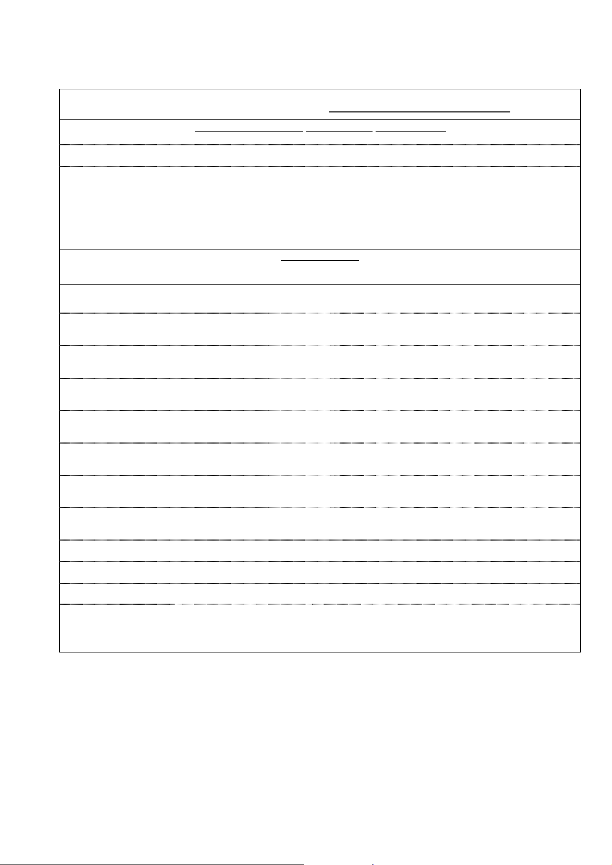
APPENDIX ‘A’. DECONTAMINATION CERTIFICATE.
Bibby Scientific Limited
Tel: +44(0)1785 812121. Fax: +44(0)1785 810405
Prior to a Service Engineer working on equipment that has been in an environment where substances hazardous to health may have been
used, you are requested to provide the following information:
Beacon Road, Stone, Staffordshire ST15 0SA. Great Britain
E-mail:
electrothermalhelp@bibby-scientific.com
DECONTAMINATION CLEARANCE CERTIFICATE
For the Inspection, Repair or Return of Medical, Laboratory or Industrial Equipment.
Company:-
Department:-
Contact Name:-
Model No:-
Tel No:-
Fax No:-
Product Description
Address:-
Post Code:-
Serial No:-
Has the equipment been exposed to any of the following, Please answer all questions by deleting YES/NO as applicable and by providing
A. Blood, body fluids, Pathological
specimens
B. Biodegradable material that could
become a hazard
C. Other biohazard YES/NO Provide details if YES
D. Chemical or substances hazardous to
health
E. Radioactive substances State name(s)
and quantities of isotopes and checks
made for residual activity
F. Other hazards YES/NO Provide details if YES
2. Please provide details of any hazard present as indicated above. Include details of names and quantities of
agents as appropriate:-
3. Your method of decontamination (please describe):-
4. Are there likely to be any areas of residual contamination (please specify)
I declare that the above information is true and complete to the best of my knowledge and belief.
Authorised signature:- Name (please print):-
Title/Position:-
For and behalf of:- Date:-
details in section 2 below.
YES/NO Provide details if YES
YES/NO Provide details if YES
YES/NO Provide details if YES
YES/NO Provide details if YES
Page 27 of 28 Digi-Mantle M7754 issue 14.4

Bibby Scientific Limited.
For the America
’s and Canada, contact:
Distributors Stamp
12. EC DECLARATION OF CONFORMITY.
CE marked products and associated accessories covered by this Instruction book conform to the
essential requirements of the following directives:
EMC Directive.
Low Voltage Directive.
A full copy of the EC Declaration / Conformity document can be obtained from the manufacture at the
email address : info@bibby-scientific.com
Beacon Road,
Stone,
Staffordshire ST15 0SA,
Great Britain.
Tel: +44(0)1785 812121
Fax: +44(0)1785 810405
• General enquiries :
info@bibby-scientific.com
• Order enquiries :
sales@bibby-scientific.com
• Technical support :
electrothermalhelp@bibbyscientific.com
• www.electrothermal.com
Part of the Bibby Scientific Group
Techne Incorporated, 3 Terri Lane,
Suite 10 Burlington, NJ 08016 USA.
Toll free:800-225-9243Tel: 609-589-2560
Fax: 609-589-2571
Email: labproducts@techneusa.com
Http www.techneusa.com
Page 28 of 28 Digi-Mantle M7754 issue 14.3
2013 Bibby Scientific Limited. All rights reserved.
 Loading...