

Page 1
Integrity 10
Operation Manual
rev 6.0
Page 2

Page 3

Contents
1. Symbols and using this instruction book .................................................................................................. 5
2. Safety information .....................................................................................................................................6
2.1. Consignes de sécurité ..................................................................................................................... 8
2.2. Sicherheitsinformationen .............................................................................................................. 11
2.3. Información de seguridad ............................................................................................................. 14
2.4. Informazioni sulla sicurezza ..........................................................................................................16
3. Introduction...............................................................................................................................................20
3.1. Instrumentspecication ................................................................................................................ 21
4. Unpacking and contents ..........................................................................................................................22
5. Installation ................................................................................................................................................23
6. Environmental protection ........................................................................................................................26
6.1. Battery disposal ............................................................................................................................26
7. Product operation ................................................................................................................................... 27
7.1. Product overview .......................................................................................................................... 27
7.2. Reductionsleeves-ttingandremoval ......................................................................................... 28
7.3. Insert SD card ............................................................................................................................... 30
7.4. Turn unit ON ................................................................................................................................30
7.5. Turn unit OFF ................................................................................................................................30
7.6. Power up ......................................................................................................................................31
7.7. Time and date setting ...................................................................................................................32
7.8. Communication protocol selection (for use with external control) .................................................33
7.9. Viewrmwarereleaseset .............................................................................................................34
7.10. Manual control ............................................................................................................................. 35
7.10.1. Setting the temperature ..........................................................................................................36
7.10.2. Setting the stir speed: .............................................................................................................. 37
7.10.3. Setting the run time ................................................................................................................37
7.10.4. Setting the ramp rate ..............................................................................................................37
7.10.5. Setting the maximum upper limit ............................................................................................38
7.10.6. Copy function .........................................................................................................................38
7.10.7. Adjusting the settings of a running cell in manual control ........................................................ 39
7.10.8. Home screen when operational ...............................................................................................40
7.11. Prolecontrol ...............................................................................................................................41
7.11.1. Prolesetup ...........................................................................................................................41
7.11.2. Setting the initial temperature .................................................................................................42
7.11.3. Setting the initial hold time .....................................................................................................42
7.11.4. Setting the initial ramp ............................................................................................................ 43
7.11.5. Setting the target temperature ................................................................................................43
7.11.6. Setting the maximum upper limit ............................................................................................44
7.11.7. Setting the plateau time .......................................................................................................... 44
7.11.8. Final temperature ....................................................................................................................45
3
Page 4

7.11.9. Final ramp ............................................................................................................................... 46
7.11.10. Setting the hold time ............................................................................................................... 46
7.11.11. Stir speed ................................................................................................................................ 47
7.11.12. Profile loop .............................................................................................................................47
7.11.13. Copyandpasteaprole..........................................................................................................48
7.11.14. In the event of power loss .......................................................................................................49
7.12. Namingandsavingaprole .........................................................................................................49
7.13 Storedproleviewandcopy ........................................................................................................51
7.13.1. Storingaprole.......................................................................................................................51
7.13.2. Deleteastoredprole .............................................................................................................54
7.14. Saving an experiment ...................................................................................................................55
7.15. Reviewing stored experiment data ................................................................................................ 57
7.15.1. Accessing stored experiment data ............................................................................................57
7.15.2. Viewing data in graphical format ............................................................................................. 59
7.15.3. Deleting experimental data ...................................................................................................... 60
7.16. OutputtingstoreddataviaUSBashdrive .................................................................................... 60
7.17. Control by contents ...................................................................................................................... 61
7.17.1.
7.17.2.
7.18. External control – optional ............................................................................................................ 63
7.18.1. PC control: ..............................................................................................................................63
8. Chemical resistance...................................................................................................................................64
Installation of the Multi-Temp .................................................................................................61
Operating the Multi-Temp ....................................................................................................... 62
9.
Reaction block dimensions ....................................................................................................................... 70
10.Powersupplyunit(PSU) specifications
11. Maintenance, service and repair..............................................................................................................72
11.1. Maintenance ................................................................................................................................72
11.2. Spillage procedure ........................................................................................................................73
11.3. Decontamination ..................................................................................................................... 73
11.4. Servicing .......................................................................................................................................73
11.5. Error and warning messages ......................................................................................................... 73
11.5.1. Heat exchanger over temperature error ...................................................................................74
11.5.2. Motor stall error ......................................................................................................................75
11.5.3. Cell failure error ......................................................................................................................75
11.5.4. Over voltage error ...................................................................................................................76
11.5.5. Under Voltage error ................................................................................................................. 76
11.5.6. Probe error ..............................................................................................................................77
12. Customer support ..................................................................................................................................... 78
13. Spares and accessories ............................................................................................................................79
14. Notes .......................................................................................................................................................... 80
15.
EU Declaration of conformity ..................................................................................................................8
................................................................................................... 71
1
Appendix 'A'...................................................................................................................................................82
4
Page 5
1. Symbols and using this instruction book
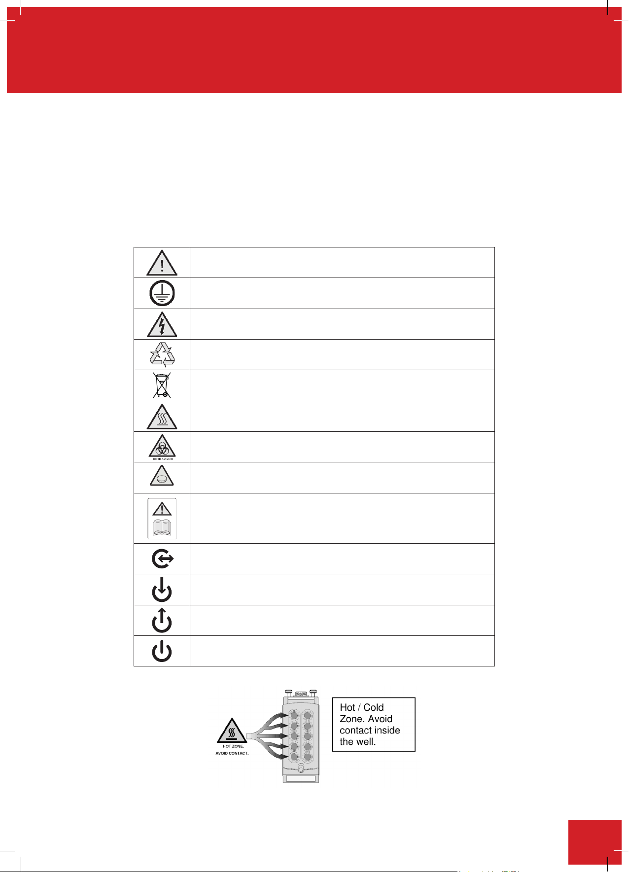
Throughoutthisinstructionbookthesymbolsdenedbelowareusedtoidentifyconditionsthatposeahazard
to the user or actions that should be observed. These symbols are also shown on the product or its packaging.
When a symbol is shown next to a paragraph or statement it is recommended the user takes particular note of
that instruction in order to prevent damage to the equipment or to prevent injury to one’s self or other people.
The Responsible Body and the Operator should read and be familiar with this Instruction book in order
to preserve the protection offered by the equipment.
To prevent injury or equipment damage it is the manufacturer’s recommendation that all persons using
this equipment are suitably trained before use.
Caution, risk of danger. See note or adjacent symbol.
Protective conductor terminal to be earthed.
Do not loosen or disconnect.
Caution / Risk of electric shock.
Recyclable Packaging Material.
Coin Battery
Do not dispose of product in normal domestic waste.
Caution. Hot surface.
Bio Chemical Hazard.
Caution required. Will require decontamination.
Contains CR2032 button coin battery.
To be disposed of according to regulations - not customer serviceable.
Refer to Instruction manual.
Port communication symbol.
Cooling fluid. Connect inlet supply to Left hand side connector
Cooling fluid. Connect inlet supply to Right hand side connector
Standby
5
Page 6
2. Safety information
DO NOT
Integrity PSU
Never
Do not
Integrity 10
Power Supply Unit
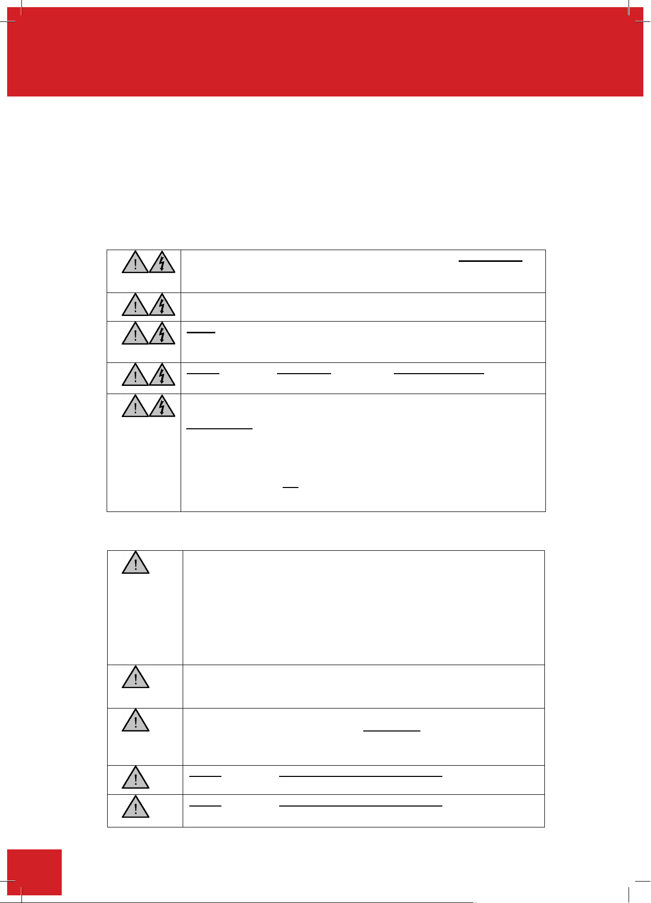
To prevent a risk of fire or electric shock,
DO NOT
open the
Integrity PSU
case without authorisation. Only qualified Service personnel should attempt to
repair/service the PSU.
Ensure the Mains Power Supply conforms to ratings found on the
data plate
located on the underside of the PSU.
Never
Operate this equipment without connection to earth/ground. Ensure the
mains supply voltage is correctly earthed/grounded in accordance with current
area legislation.
Do not
position the
Integrity 10
on top of the
Power Supply Unit
In the event of a single fault condition causing a cell within the unit to go over-
temperature, there is additional protection within the cell in the form of a
Thermal Fuse.
The Thermal Fuse is designed to protect a faulty cell continually heating
beyond a temperature of approx. 190°C.
The Thermal Fuse is not designed to protect individual samples being heated
beyond a specified temperature; additional means should be employed if that
level of protection is required.
Do not
Integrity 10 or Power Supply Unit
Do not
Integrity 10 or Po
wer Supply Unit
This product has been designed for safe operation when used as detailed in accordance with the
Manufacturer’s instructions.
NOTE: Failure to use this equipment in accordance with the manufactures operating instructions may
compromise your basic safety protection afforded by the equipment and may invalidate the
warranty/guarantee. The warranty/guarantee does not cover damage caused by faulty installation or
misuse of the equipment.
Prevention of Fire and Electric Shock
To prevent a risk of fire or electric shock,
case without authorisation. Only qualified Service personnel should attempt to
repair/service the PSU.
Ensure the Mains Power Supply conforms to ratings found on the data plate
located on the underside of the PSU.
General Safe Operating Practice
Operate this equipment without connection to earth/ground. Ensure the
mains supply voltage is correctly earthed/grounded in accordance with current
area legislation.
position the
In the event of a single fault condition causing a cell within the unit to go overtemperature, there is additional protection within the cell in the form of a
Thermal Fuse.
The Thermal Fuse is designed to protect a faulty cell continually heating
beyond a temperature of approx. 190°C.
The Thermal Fuse is not designed to protect individual samples being heated
beyond a specified temperature; additional means should be employed if that
level of protection is required.
on top of the
open the
Alway
s follow good laboratory practice when using this equipment. Give due
recognition to your company’s safety and legislative health & safety
procedures and all associated legislation applicable to your areas of
operation. Check laboratory procedures for substances being heated and
ensure all hazards (e.g. risk of explosion, implosion or the release of toxic or
flammable gases) that might arise have been suitably addressed before
proceeding. When heating certain substances the liberation of hazardous
gases may require the use of a fume cupboard or other means of extraction.
(Consult your company practice).
Ensur
e equipment is used on a clean, dry, non-combustible, solid work
surface with at least 300mm of suitable clearance all around from other
equipment.
Ensur
e the PSU is positioned on a clean, dry, non-combustible surface with a
sufficient space for the power cable to Integrity 10 and mains input lead and
plug set to enter/exit without undue bend stresses. Ensure a suitable
clearance for air flow and heat dissipation.
position the
connect/disconnect from the power cable assembly.
position the
connect/disconnect from the coolant fluid supply.
so that it is difficult to
so that it is difficult to
6
Page 7
Do not
position the
Integrity 10 or Power Supply Unit
Do not
Do not
Do not
not
Do not
Do not
Do not
Touch Screen Warning.
Warning
Warning
Warning
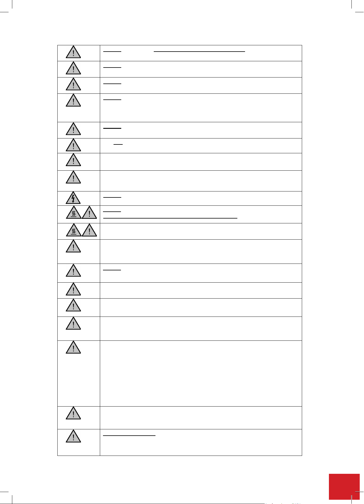
Care must be taken
connect/disconnect data and communication cables.
position the PSU so that the on/off switch or IEC mains socket
located on the rear is inaccessible.
immerse any part of this equipment in water/fluid.
spill substances on the touch screen. Case materials are protected as
defined in Table 8.1 Chemical resistance chart. If spillage does occur,
disconnect unit from mains supply and follow instructions as detailed in
Section ‘Maintenance, Service and Customer Repair’.
Do not cover the Integrity 10 or PSU (ESPECIALLY VENTILATION SLOTS)
whilst in use.
It is
operation.
Only use Original Equipment Manufacture’s Parts and Accessories. Ref
Section 11.
The equipment is not spark, flame or explosion proof and has not been
designed for use in hazardous areas in terms of BSEN 60079-14:1997. Keep
flammable, low flash point substances away from the apparatus.
Take care when handling HOT & COLD glassware
recommended to leave any heating apparatus unattended during
operate or handle any part of this product with wet hands.
touch the inside of the cells when the product is in operation.
so that it is difficult to
Ensure the unit has reached ambient temperature before removing the top
cover.
When the top cover has been removed and the inside of the unit is exposed
do not put fingers into the front or rear of the unit as there is the risk that they
can become trapped.
lean or stretch over the unit when in operation.
Keep the Mains Plug and Lead set cable away from the heating surface.
The screen is impervious to acetone. It is
recommended that any chemical spillage is wiped off the screen immediately.
: Standard glassware supplied for the Integrity product is not
designed for high pressure applications. Maximum operating pressure of
standard glassware with cap fitted is 0.5bar.
: Glass vessels can explode or implode violently, either
spontaneously from stress failure caused by pressure or vacuum, or from
accidental impact.
Carefully check glass vessels for star cracks, scratches or etching marks
before each use. Cracks can increase the likelihood of breakage or may allow
chemicals to leak into the equipment.
Conduct all pressure and vacuum operations in glass vessels behind
adequate shielding and use Personnel Protective Equipment (Full face guard,
gloves, protective clothing) during handling.
: Glass vessels which have been located in a block at a high
temperature should not be placed into a cold block as this is likely to shatter
the vessel.
when using flammable solvents. Approaches which
could be adopted to reduce the risk of fire include introducing an inert
atmosphere inside of the reaction tubes and/or using the equipment in a
properly ventilated area, e.g. under a fume hood.
7
Page 8
Additional safety information
Additional safety information
ATS20002
and
ATS20003
PTFE caps
For individual components see below.
Viton (main
seal) and O
rings.
Viton is resistant to a wide range of chemicals including oils, aqueous media
and most other fluids.
It is recommended that the user checks the chemical compatibility prior to
use.
PFTE Cap PTFE is resistant to a wide range of chemicals including ozone, chlorine,
acetic acid, ammonia sulphuric acid and hydrochloric acid. The only
chemicals known to affect these coatings are molten alkali metals and highly
reactive fluorinating agents.
It is recommended that the user checks the chemical compatibility prior to
use.
Silicone Cap
Septum
Peroxide cross linked HTV silicone rubber, classified in accordance with
ASTM D 1418 as VMQ. It is recommended that the user checks the chemical
compatibility prior to use.
316 Stainless
steel 2mm dia
sampling hole
bung
It is recommended that the user checks the chemical compatibility prior to
use.
2.1. CONSIGNES DE SÉCURITÉ
ATS20002 For individual components see below.
and ATS20003
PTFE caps
Viton (main Viton is resistant to a wide range of chemicals including oils, aqueous media and most other
seal)andO uids.
rings. It is recommended that the user checks the chemical compatibility prior to use.
PTFE Cap PTFE is resistant to a wide range of chemicals including ozone, chlorine, acetic acid,
SiliconeCap PeroxidecrosslinkedHTVsiliconerubber,classiedinaccordancewithASTMD1418as
Septum VMQ. It is recommended that the user checks the chemical compatibility prior to use.
ammonia sulphuric acid and hydrochloric acid. The only chemicals known to affect these
coatingsaremoltenalkalimetalsandhighlyreactiveuorinatingagents.
It is recommended that the user checks the chemical compatibility prior to use.
316 Stainless steel It is recommended that the user checks the chemical compatibility prior to use.
2mm dia sampling
hole bung
PTFE sampling
hole bung
2.1. Consignes de sécurité
Ce produit a été conçu pour fonctionner en toute sécurité lorsqu’il est utilisé conformément aux instructions du
fabricant.
REMARQUE : Ne pas utiliser ce matériel en conformité avec les instructions de fonctionnement du fabricant peut
compromettre la protection de sécurité de base offerte par ce matériel et peut annuler la garantie. La garantie ne
couvre pas les dommages causés par une mauvaise installation ou une mauvaise utilisation du matériel.
Prévention des incendies et des chocs électriques
PTFE is resistant to a wide range of chemicals including ozone, chlorine, acetic acid,
ammonia sulphuric acid and hydrochloric acid. The only chemicals known to affect these
coatingsaremoltenalkalimetalsandhighlyreactiveuorinatingagents.
commended that the user chIt is re ecks the chemical compatibility prior to use.
Pour éviter tout risque d'incendie ou de choc électrique, N'OUVREZ PAS le
bloc d'alimentation Integrity sans autorisation. Seul du personnel de
maintenance qualifié peut tenter de réparer ou d'entretenir le bloc
d'alimentation.
Veillez à ce que l'alimentation électrique du secteur soit conforme aux classes
figurant sur la plaque signalétique située sur la partie inférieure du bloc
d'alimentation.
Ne jamais faire fonctionner le matériel sans mise à la terre/masse. Veillez à
ce que la tension du secteur soit correctement mise à la terre/masse
conformément à la législation en vigueur dans votre pays.
Ne placez pas l'Integrity 10 au dessus du bloc d'alimentation
En cas de défaillance causant la surchauffe d'une cellule de l'appareil, il existe
une protection supplémentaire à l'intérieur de la cellule sous la forme d'un
fusible thermique.
Le fusible thermique est conçu pour protéger une cellule défectueuse
continuant à chauffer au delà de 190 °C environ.
8
Page 9
Le fusible thermique n'est pas conçu pour protéger des échantillons
Ne placez pas
l'Integrity 10
ou le bloc d'alimentation
Ne placez pas
l'Integrity 10 ou le bloc d'alimentation
Ne placez pas
l'Integrity 10 ou le bloc d'alimentation
Ne placez pas
Ne
Ne
n'e
st pas
Ne
individuels qui seraient chauffés au delà d'une température spécifique ; des
moyens supplémentaires doivent être utilisés si ce niveau de protection est
nécessaire.
Pratiques de base pour une utilisation sûre
Suivez toujours les bonnes pratiques de laboratoire lors de l'utilisation de cet
appareil. Portez une attention particulière aux procédures de santé et de
sécurité de votre entreprise et aux procédures réglementaires, ainsi qu'à
toutes les lois applicables associées en vigueur dans votre pays. Vérifiez les
procédures de laboratoire pour connaître les substances qui sont chauffées
et veillez à ce que tous les dangers (par exemple le risque d'explosion,
d'implosion et de dégagement de gaz toxiques ou inflammables) qui peuvent
survenir ont été convenablement traités avant de poursuivre. Lorsque
certaines substances sont chauffées, le dégagement de gaz dangereux peut
nécessiter l'utilisation d'une hotte aspirante ou d'autres moyens d'extraction.
(Consultez les pratiques de votre entreprise).
Veillez à ce que le matériel soit utilisé sur une surface propre, sèche,
incombustible et solide avec un espace suffisant d'au moins 300 mm tout
autour du matériel.
Veillez à ce que le bloc d'alimentation soit placé sur une surface propre,
sèche et incombustible avec suffisamment d'espace afin que le câble
d'alimentation allant vers l'Integrity 10 et l'ensemble des câbles et fiches
secteur puissent être insérés ou sortis sans être pliés de manière excessive.
Veillez à maintenir un espace suffisant pour la circulation d'air et la
dissipation de la chaleur.
difficile de raccorder ou de débrancher l'ensemble des câbles d'alimentation.
difficile de raccorder ou de débrancher l'alimentation en fluide de
refroidissement.
difficile de raccorder ou de débrancher les câbles de transfert de données et
de communication.
le bloc d'alimentation de sorte que le commutateur
marche/arrêt ou la prise secteur CEI situés à l'arrière soient inaccessibles.
plongez pas de pièces de cet appareil dans de l'eau ou dans un fluide.
de sorte qu'il soit
de sorte qu'il soit
de sorte qu'il soit
renversez pas de substances sur l'écran tactile. Les matériaux du boîtier
sont protégés tel que défini dans le tableau 8.1 listant les résistances
chimiques. Si une substance est renversée, débranchez l'appareil du secteur
et suivez les instructions détaillées dans le paragraphe « Maintenance,
entretien et réparation par le client ».
Ne couvrez pas l'Integrity 10 ou le bloc d'alimentation (EN PARTICULIER
LES FENTES D'AÉRATION) lorsqu'ils fonctionnent.
Il
surveillance pendant son fonctionnement.
N'utilisez que des pièces et des accessoires d'origine provenant du fabricant
du matériel. Réf. paragraphe 11.
Le matériel n'est pas résistant aux étincelles, au feu ou aux explosions et n'a
pas été conçu pour être utilisé dans des zones dangereuses au sens de la
norme BSEN 60079-14:1997. Maintenez les substances inflammables à
point éclair bas éloignées de l'appareil.
faites fonctionner ni ne manipulez aucune pièce de ce produit avec les
mains mouillées.
recommandé de laisser tout appareil de chauffage sans
9
Page 10
Ne
touchez pas l'intérieur des cellules lorsque l'appareil est en
Ne
Avertissement concernant l'écran tactile.
Attention
Attention
Atte
ntion
Des précautions doivent être prises
fonctionnement.
Faites attention lorsque vous manipulez de la verrerie CHAUDE ou
FROIDE.
Veillez à ce que l'appareil ait atteint la température ambiante avant d'ôter le
couvercle.
Lorsque
mettez pas vos doigts à l'avant ou à l'arrière de l'appareil car ils risqueraient
d'être piégés.
fonctionnement.
Éloignez les fiches secteurs et les câbles de toute surface chauffante.
Il est recommandé d'essuyer immédiatement tout produit chimique renversé
sur l'écran.
conçue pour des utilisations à haute pression. La pression de fonctionnement
maximale d'une verrerie standard équipée d'un bouchon est de 0,5 bar.
soit spontanément par rupture de contrainte causée par la pression ou le
vide, ou à cause d'un impact accidentel. Avant chaque utilisation, vérifiez
soigneusement les récipients en verre à la recherche de craquelures étoilées,
de rayures ou de marques de gravure. Les craquelures peuvent augmenter la
probabilité de casse ou permettre aux produits chimiques de s'infiltrer dans
l'appareil. Réalisez toutes les opérations sous pression ou sous vide dans
des récipients en verre derrière une protection adaptée et utilisez des
équipements de protection individuels (protection faciale complète, gants,
vêtements de protection) pendant la manipulation.
le couvercle a été ôté et que l'intérieur de l'appareil est exposé, ne
vous penchez pas ou ne vous allongez pas sur l'appareil lorsqu'il est en
L'écran est résistant à l'acétone.
: La verrerie standard fournie pour l'appareil Integrity n'est pas
: Les récipients en verre peuvent exploser ou imploser violemment,
: Les récipients en verre qui ont été placés dans un bloc à haute
température ne doivent pas être placés dans un bloc froid car cela est
susceptible de les briser.
lorsque des solvants inflammables
sont utilisés. Les approches qui pourraient être adoptées pour réduire le
risque d'incendie incluent l'introduction d'une atmosphère inerte à l'intérieur
des tubes de réaction et/ou l'utilisation de l'appareil dans une zone
correctement ventilée, comme par exemple sous une hotte aspirante.
Informations complémentaires concernant la sécurité
Bouchons en
PTFE
ATS20002 et
ATS20003.
Viton (joint
principal) et
joints
toriques.
Bouchon en
PTFE
Pour les composants individuels, voir ci-dessous.
Le Viton est résistant à un grand nombre de produits chimiques tels que
l'huile, les milieux aqueux et la plupart des autres fluides.
Il est recommandé à l'utilisateur de vérifier la compatibilité chimique avant
toute utilisation.
Le PTFE est résistant à un large éventail de produits chimiques y compris
l'ozone, le chlore, l'acide acétique, le sulfate d'ammonium et l'acide
chlorhydrique. Les seuls produits chimiques connus pouvant avoir un effet
sur ces revêtements sont les métaux alcalins fondus et les agents de
fluoration très réactifs.
Il est recommandé à l'utilisateur de vérifier la compatibilité chimique avant
10
Page 11
toute utilisation.
toute utilisation.
Bouchon et
cloison en
silicone
Caoutchouc de silicone HTV réticulé au peroxyde, classé de type VMQ selon
la norme ASTM D 1418. Il est recommandé à l'utilisateur de vérifier la
compatibilité chimique avant toute utilisation.
Bouchon du
trou de
l'échantillon
de 2 mm de
diamètre en
acier
inoxydable
316
Il est recommandé à l'utilisateur de vérifier la compatibilité chimique avant
toute utilisation.
2.2. SICHERHEITSINFORMATIONEN
Dieses Produkt kann unter Einhaltung der Herstelleranweisungen sicher betrieben werden.
HINWEIS: Wird das Gerät nicht gemäß den Bedienungsanweisungen des Herstellers verwendet, kann
dies dazu führen, dass Ihr grundlegender Sicherheitsschutz durch das Gerät beeinträchtigt und die
Gewährleistung/Garantie ungültig wird. Die Gewährleistung/Garantie deckt keine Schäden durch
fehlerhafte Installation oder falsche Verwendung des Geräts ab.
Vermeiden von Feuer und Stromschlägen
niemals
Integrity 10
nicht
Netzteil
Bouchon et
cloison en
silicone
Bouchon du
trou de
l'échantillon
2.2. Sicherheitsinformationen
Dieses Produkt kann unter Einhaltung der Herstelleranweisungen sicher betrieben werden.
HINWEIS: Wird das Gerät nicht gemäß den Bedienungsanweisungen des Herstellers verwendet, kann dies dazu
führen, dass Ihr grundlegender Sicherheitsschutz durch das Gerät beeinträchtigt und die Gewährleistung/Garantie
ungültig wird. Die Gewährleistung/Garantie deckt keine Schäden durch fehlerhafte Installation oder falsche
de 2 mm de
diamètre en
acier
inoxydable
316
Caoutchouc de silicone HTV réticulé au peroxyde, classé de type VMQ selon
la norme ASTM D 1418. Il est recommandé à l'utilisateur de vérifier la
compatibilité chimique avant toute utilisation.
Il est recommandé à l'utilisateur de vérifier la compatibilité chimique avant
toute utilisation.
Verwendung des Geräts ab.
Vermeiden von Feuer und Stromschlägen
Um die Gefahr von Bränden oder Stromschlägen zu verhindern, öffnen Sie
das Gehäuse des Integrity-Netzteils NICHT ohne Genehmigung. Nur
qualifiziertes Wartungspersonal darf das Netzteil reparieren/warten.
Allgemeine sichere Betriebspraxis
Stellen Sie sicher, dass die Netzstromversorgung den auf dem Datenschild
auf der Unterseite des Netzteils angegebenen Nennleistungen entspricht.
Betreiben Sie das Gerät
sicher, dass die Netzspannung in Übereinstimmung mit der entsprechenden
aktuellen Gesetzgebung korrekt geerdet ist.
Stellen Sie das
Bei Auftreten eines Einzelfehlers, der dazu führt, dass eine Zelle im Netzteil
eine Übertemperatur aufweist, besteht ein zusätzlicher Schutz in der Zelle in
Form einer thermischen Sicherung.
Die thermische Sicherung sorgt dafür, dass sich die fehlerhafte Zelle nicht
über eine Temperatur von etwa 190 °C hinaus aufheizt.
Die thermische Sicherung ist nicht dafür ausgelegt, einzelne Proben vor der
weiteren Aufheizung über eine bestimmte Temperatur hinaus zu schützen;
falls dieser Schutz erforderlich ist, sind zusätzliche Mittel zu verwenden.
Befo
Beachten Sie die Sicherheitsverfahren Ihres Unternehmens, die gesetzlichen
Gesundheits- und Sicherheitsverfahren sowie sämtliche, damit verbundenen
Rechtsvorschriften, die für Ihre Arbeitsgebiete gelten. Überprüfen Sie die
Laborverfahren für die erhitzten Stoffe und stellen Sie sicher, dass alle
potenziellen Gefahren (z.B. Explosionsgefahr, Implosionsgefahr bzw. Gefahr
der Freisetzung von toxischen oder entzündlichen Gasen) auf angemessene
Weise berücksichtigt wurden, bevor die Arbeit fortgesetzt wird. Beim
Erhitzen von bestimmten Stoffen kann es durch die Freisetzung von
gefährlichen Gasen eventuell notwendig sein, dass ein Laborabzug oder eine
andere Art des Abzugs verwendet wird. (Orientieren Sie sich an den
ohne Erd-/Masseverbindung. Stellen Sie
auf das
lgen Sie bei der Verwendung des Geräts immer die gute Laborpraxis.
11
Page 12
Vorgehensweisen Ihres Unternehmen
s.)
Integrity 10
-
Gerät bzw. das Netzteil
nicht
Integrity 10
-
Gerät bzw. das Netzteil
nicht
Integrity 10
-
Gerät bzw. das Netzteil
nicht
nicht
kein
keine
nicht
keine
nicht,
Stellen Sie sicher, dass sich das Gerät auf einer sauberen, trockenen, nicht
brennbaren und festen Arbeitsfläche mit einem geeigneten Abstand von
mindestens 300 mm in jede Richtung von anderen Geräten befindet.
Überprüfen Sie, dass sich das Netzteil auf einer sauberen, trockenen, nicht
brennbaren Fläche befindet und ausreichend Platz für das Stromkabel zum
Integrity 10-Gerät und die Netzeingangsleitung bzw. den Steckersatz für den
Eingang/Ausgang vorhanden ist und keine unzulässige Biegebeanspruchung
herrscht. Achten Sie auf einen geeigneten Abstand für die Luftströmung und
Wärmeabgabe.
Stellen Sie das
Anschluss an bzw. die Trennung vom Stromkabel erschwert wird.
Stellen Sie das
Anschluss an bzw. die Trennung von der Kühlflüssigkeitszuführung erschwert
wird.
Stellen Sie das
Anschluss bzw. die Trennung von Daten- und Kommunikationskabeln
erschwert wird.
Stellen Sie das Netzteil
Netzsteckdose auf der Rückseite unzugänglich sind.
Tauchen Sie
Verschütten Sie
Gehäusematerialien verfügen über den in Tabelle 8.1 "Darstellung der
chemischen Beständigkeit" angegebenen Schutz. Wurden Stoffe verschüttet,
trennen Sie die Einheit von der Netzstromversorgung und befolgen die
Anweisungen des Abschnitts "Wartung, Instandhaltung und Reparaturen".
Verdecken Sie das Integrity 10-Gerät bzw. das Netzteil
(INSBESONDERE BELÜFTUNGSSCHLITZE) während der Nutzung
nicht.
Es wird
zu lassen.
Teil dieses Gerätes in Wasser/eine Flüssigkeit.
Stoffe auf dem Touch Screen. Die
empfohlen, ein Heizgerät während des Betriebs unbeaufsichtigt
so hin, dass der An-/Aus-Schalter oder die IEC-
so hin, dass der
so hin, dass der
so hin, dass der
12
Verwenden Sie nur Teile und Zubehör von Originalgeräteherstellern. Siehe
Abschnitt 11.
Das Gerät ist nicht funkengeschützt, flammbeständig oder
explosionsgeschützt und wurde nicht für die Nutzung in gefährlichen
Bereichen gemäß BSEN 60079-14:1997 ausgelegt. Halten Sie entzündliche
Stoffe mit niedrigem Flammpunkt vom Gerät fern.
Bedienen bzw. fassen Sie
Berühren Sie das Innere der Zellen
befindet.
Vorsicht bei der Handhabung von HEISSEN & KALTEN Glaswaren
Achten Sie darauf, dass die Einheit Raumtemperatur erreicht hat, bevor Sie
die obere Abdeckung entfernen.
Teile des Produkts mit nassen Händen an.
wenn sich das Produkt in Betrieb
Page 13
S
nicht
Touch Screen
-
Warnung.
Warnung
Warnung
Warnung
Vorsicht
tecken Sie, nachdem die obere Abdeckung entfernt wurde und das Innere
der Einheit offen ist, Ihre Finger nicht in den vorderen oder hinteren Teil der
Einheit, da sie eingeklemmt werden könnten.
Le
hnen bzw. beugen Sie sich während des Betriebs
Halten Sie den Netzstecker und das Leitungskabel von der Heizfläche fern.
Der Bildschirm ist unempfindlich gegen Aceton. Es
wird empfohlen, eventuell verschüttete chemische Stoffe sofort vom
Bildschirm abzuwischen.
: Standardglas, das für das Integrity-Produkt geliefert wird, ist nicht
für Hochdruckanwendungen geeignet. Der maximale Betriebsdruck für
Standardglas mit installierter Kappe beträgt 0,5 bar.
: Glasbehälter können entweder spontan aufgrund von zu starker
Belastung durch den Druck oder das Vakuum oder durch unbeabsichtigte
Einwirkung heftig explodieren oder implodieren.
Prüfen Sie Glasbehälter vor jeder Nutzung sorgfältig auf Risse, Kratzer oder
Ätzspuren. Risse können die Wahrscheinlichkeit eines Bruchs erhöhen bzw.
dazu führen, dass Chemikalien in das Gerät gelangen.
Führen Sie alle Druck- und Vakuumvorgänge in Glasbehältern nur hinter
geeigneten Blenden durch und tragen Sie während der Handhabung eine
Persönliche Schutzausrüstung (vollständige Gesichtsmaske, Handschuhe,
Schutzkleidung).
: Glasbehälter, die in einen Block mit einer hohen Temperatur
gestellt wurden, dürfen nicht in einen kalten Block gestellt werden, da der
Behälter dadurch wahrscheinlich zerspringen wird.
über die Einheit.
bei der Verwendung von entzündlichen Lösungsmitteln.
Maßnahmen zur Verringerung der Brandgefahr umfassen u.a. die Schaffung
einer inerten Atmosphäre in den Reaktionsgefäßen und/oder Verwendung
des Geräts in einem gut belüfteten Bereich, z. B. unter einer Abzugshaube.
Weitere sicherheitsinformationen
ATS20002
Was einzelne Komponenten betrit, siehe unten.
und
ATS20003
PTFEKappen
Viton
(Hauptdichtu
Viton ist beständig gegen eine Vielzahl von Chemikalien, darunter Öle,
wässrige Medien und die meisten anderen Flüssigkeiten.
ng) und ORinge.
Es wird empfohlen, dass der Nutzer die chemische Verträglichkeit vor der
Verwendung prüft.
PTFE-Kappe
PTFE ist beständig gegen eine Vielzahl von Chemikalien, darunter Ozon,
Chlor, Ethansäure, Ammoniak, Schwefelsäure und Chlorwasserstosäure.
Die einzigen Chemikalien, die diese Beschichtungen nachweislich angreifen, sind geschmolzene Alkalimetalle und hochreaktive Fluorierungsmittel.
Es wird empfohlen, dass der Nutzer die chemische Verträglichkeit vor der
Verwendung prüft.
Silikonkappe
nseptum
Peroxidisch vernetzter HTV-Silikonkautschuk, klassiziert gemäß ASTM
D 1418 als VMQ. Es wird empfohlen, dass der Nutzer die chemische
Verträglichkeit vor der Verwendung prüft.
13
Page 14
316
Edelstahl
2 mm
Durchmesser
Stöpsel
Probenahme
-Loch
Es wird empfohlen, dass der Nutzer die chemische Verträglichkeit vor der
Verwendung prüft.
2.3. INFORMACIÓN DE SEGURIDAD
Este producto ha sido diseñado para funcionar de forma segura si se emplea de acuerdo con las
instrucciones del fabricante.
NOTA: de no utilizarse este equipo de acuerdo con las instrucciones de manejo del fabricante, la
protección básica de seguridad del usuario que ofrece el equipo puede verse comprometida y podría
invalidarse la garantía. La garantía no cubre los daños derivados de una instalación incorrecta o del uso
indebido del equipo.
Nunca
No
Integrity
10
fuente de alimentación
316
Edelstahl
-Loch
Es wird empfohlen, dass der Nutzer die chemische Verträglichkeit vor der
2 mm
Durchmesser
Stöpsel
Probenahme
Verwendung prüft.
2.3. Información de seguridad
Este producto ha sido diseñado para funcionar de forma segura si se emplea de acuerdo con las instrucciones del
fabricante.
NOTA: de no utilizarse este equipo de acuerdo con las instrucciones de manejo del fabricante, la protección básica
de seguridad del usuario que ofrece el equipo puede verse comprometida y podría invalidarse la garantía. La
garantía no cubre los daños derivados de una instalación incorrecta o del uso indebido del equipo.
Prevención de incendios y descargas eléctricas
Para evitar riesgos de incendio o descarga eléctrica, NO abra la caja de la
fuente de alimentación (PSU) de Integrity sin autorización. Solo el personal
debidamente cualificado debe realizar las tareas de reparación o
mantenimiento de la PSU.
Asegúrese de que la conexión a la red eléctrica cumple las especificaciones
indicadas en la placa de identificación situada en la cara inferior de la PSU.
utilice este equipo sin conexión a tierra. Asegúrese de que la tensión
de la red eléctrica tiene conexión a tierra de acuerdo con la legislación
vigente local.
coloque la
sobre la
.
En caso de que se produjera un fallo que causara el sobrecalentamiento de
una celda de la unidad, esta dispone de protección adicional en forma de
termofusible.
El
termofusible está diseñado para proteger celdas defectuosas que se
sobrecalientan continuamente por encima de los 190 °C aproximadamente.
El termofusible no está diseñado para proteger muestras individuales que
sobrepasan una determinada temperatura; deben emplearse otros medios en
caso de que sea necesario ese nivel de protección.
Práctica operativa y de seguridad estándar
Si
ga siempre las buenas prácticas de laboratorio cuando use este equipo.
Tenga debidamente en cuenta los procedimientos legislativos de seguridad y
de salud y seguridad de su compañía y toda la legislación asociada aplicable
en las zonas de operación. Compruebe los procedimientos de laboratorio
relacionados con las sustancias susceptibles de calentarse y asegúrese de
controlar todos los riesgos (p. ej. riesgo de explosión, implosión o liberación
de gases tóxicos o inflamables) que puedan surgir antes de continuar.
Cuando caliente determinadas sustancias, la liberación de gases peligrosos
puede exigir el uso de una campana de humos u otros medios de extracción.
(Consulte las prácticas de su empresa.)
As
egúrese de que el equipo se utiliza sobre una superficie de trabajo firme,
limpia, seca y no combustible y que esté separado al menos 300 mm de
otros equipos de su entorno.
14
Page 15
Asegúrese de que la PSU se encuentra en una superficie limpia, seca y no
No
Integrity
10 o la fuente de alimentación
No
Integrity
10 o la fuente de alimentación
No
Integrity
10 o la fuente de alimentación
No
No
No
No
No
No
No
Advert
encia sobre la pantalla táctil.
Advertencia
Advertencia
combustible con espacio suficiente para el cable de alimentación que se
conecta a Integrity 10 y que el cable de alimentación y el enchufe de la red
pueden conectarse y desconectarse sin que se doblen. Asegúrese que hay
espacio suficiente para que fluya el aire y se disipe el calor.
coloque la
difícil conectarlas o desconectarlas del conector del cable de alimentación.
coloque la
difícil conectarlas o desconectarlas del suministro de líquido refrigerante.
coloque la
difícil conectar o desconectar los cables de datos y comunicación.
coloque la PSU de modo que el interruptor de encendido y apagado o la
toma de corriente IEC situada en la parte posterior queden inaccesibles.
sumerja ninguna pieza de este equipo en agua o líquidos.
derrame sustancias sobre la pantalla táctil. Los materiales de la carcasa
están protegidos tal y como se indica en la Tabla 8.1 Tabla de resistencia
química. Si se produce algún derrame, desconecte el equipo de la red
eléctrica y siga las indicaciones de la sección "Mantenimiento, servicio y
reparación por parte del cliente".
No cubra la Integrity 10 ni la PSU (ESPECIALMENTE LAS RANURAS
DE VENTILACIÓN) mientras están en funcionamiento.
es recomendable dejar desatendido ningún aparato calefactor mientras
está funcionando.
Utilice únicamente piezas y accesorios del fabricante del equipo original.
Consúltese la sección 11.
de modo que resulte
de modo que resulte
de modo que resulte
Este equipo no ha sido diseñado a prueba de chispas, llamas o explosión y
no ha sido concebido para su uso en zonas peligrosas previstas en la norma
BSEN 60079-14:1997. Mantenga alejadas del aparato las sustancias que
sean inflamables y tengan un punto de ignición bajo.
utilice ni manipule ninguna pieza de este producto con las manos
húmedas.
toque el interior de las celdas cuando el aparato esté funcionando.
Extreme la precaución cuando maneje vidrio CALIENTE y FRÍO
Asegúrese de que la unidad alcanza la temperatura ambiente antes de retirar
la tapa superior.
Una vez que se retire la tapa superior y quede expuesto el interior de la
unidad, no introduzca los dedos en la parte delantera o trasera de dicha
unidad ya que podría pillárselos.
se apoye o estire sobre la unidad cuando esté funcionando.
Mantenga el enchufe de red y el cable separados de la superficie de
calentamiento.
La pantalla es impermeable a la
acetona. Se recomienda limpiar inmediatamente cualquier derrame de
sustancias químicas sobre la pantalla.
: el vidrio estándar suministrado para el producto Integrity no
está diseñado para aplicaciones a altas presiones. La presión máxima de
funcionamiento del vidrio estándar con la tapa puesta es de 0,5 bares.
: los recipientes de vidrio pueden explotar o implosionar de
forma violenta, ya sea de manera espontánea por un fallo de tensión debido
a la presión o el vacío, ya sea por un golpe accidental.
Compruebe bien que los recipientes de vidrio no presentan grietas, arañazos
15
Page 16

o marcas de grabado antes de usarlos. Las grietas pueden aumentar la
Advertencia
Deben extremarse las precauciones
probabilidad de rotura o de fugas de productos químicos en el equipo.
Realice todas las operaciones de presión y vacío en los recipientes de vidrio
tras una pantalla de protección adecuada y utilice equipos de protección
personal (máscara completa, guantes y prendas de protección) durante su
manipulación.
: los recipientes de vidrio que se hayan colocado en un bloque a
altas temperaturas no deben introducirse en un bloque frío, ya que es
probable que se hagan añicos.
inflamables. Algunos métodos que pueden emplearse para reducir el riesgo
de incendio consistirían en introducir una atmósfera inerte en los tubos de
reacción o emplear los equipos en zonas bien ventiladas, p. ej. bajo una
campana de humos.
Información complementaria acerca de la seguridad
Tapones de
politetrauoroetileno
(PTFE) ATS20002 y
ATS20003.
Juntas de Viton
(junta principal) y
tórica.
Para componentes individuales, véase más abajo.
El Viton es resistente a una gran variedad de agentes químicos como
los aceites, los medios acuosos y la mayoría del resto de líquidos.
Se recomienda al usuario que compruebe la compatibilidad química
antes de su utilización.
cuando se utilicen disolventes
Tapón de PTFE.
Diafragma del
tapón
de silicona.
Tapón para
agujeros de
muestreo de acero
inoxidable 316 de
2 mm de diámetro.
2.4. Informazioni sulla sicurezza
Il presente prodotto è stato progettato per un funzionamento sicuro quando utilizzato secondo le istruzioni
del fabbricante.
El PTFE es resistente a una gran variedad de agentes químicos como
el ozono, cloro, ácido acético, ácido sulfúrico de amoníaco y ácido
hidroclórico. Los únicos productos químicos que se sabe que afectan
a estos revestimientos son los metales alcalinos fundidos y los
agentes uorantes altamente reactivos.
Se recomienda al usuario que compruebe la compatibilidad química
antes de su utilización.
Caucho silicónico HTV reticulado por peróxido, clasicado de acuerdo
con ASTM D 1418 como VMQ. Se recomienda al usuario que
compruebe la compatibilidad química antes su utilización.
Se recomienda al usuario que compruebe la compatibilidad química
antes su utilización.
NOTA: Il mancato rispetto delle istruzioni operative fornite dal fabbricante può compromettere la sicurezza
di base offerta dall’apparecchiatura e rendere nulla la garanzia. La garanzia non copre i danni causati da
un’installazione scorretta o da un uso improprio dell’apparecchiatura.
16
Page 17
NON
mai
Non
Integrity 10
unità di alimentazione (PSU)
Non
Integrity 10 o l'unità di alimentazione
Non
Integrity 10 o l'unità di alimentazione
Non
Integrity 10 o l'unità di alimentazione
Non
Non
Prevenzione degli incendi e delle scosse elettriche
Per evitare il rischio di incendio o scossa elettrica,
dell'unità di alimentazione (PSU) di Integrity senza autorizzazione. Solo il
personale qualificato addetto alla manutenzione può tentare di
riparare/manutenere l'unità di alimentazione (PSU).
Assicurarsi che l'alimentazione della rete elettrica sia conforme ai dati
nominali indicati nella targhetta identificativa posizionata sul lato inferiore
dell'unità di alimentazione (PSU).
Non utilizzare
terra/massa. Assicurarsi che la tensione di alimentazione sia correttamente
messa a terra/massa in conformità con la legislazione vigente nel proprio
paese.
posizionare
Se si verifica una condizione di primo guasto che fa sì che una cella all'interno
dell'unità sia in sovratemperatura, nella cella è presente un fusibile termico
che funge da ulteriore protezione.
Il fusibile termico è progettato per proteggere una cella in guasto che riscalda
continuativamente a una temperatura che supera approssimativamente i 190
°C .
Il fusibile termico non è progettato per proteggere i singoli campioni che
vengono riscaldati oltre una determinata temperatura; se si necessita di un
tale livello di protezione occorre adottare altre misure.
questa apparecchiatura senza il collegamento di
sopra l'
aprire l'alloggiamento
Pratica di utilizzo sicuro generale
Seguire sempre le buone pratiche di laboratorio quando si utilizza questa
apparecchiatura. Prendere conoscenza e implementare le procedure per la
salute e la sicurezza vigenti, quelle stabilite dalla propria azienda e da
qualsiasi normativa applicabile alla propria area di lavoro. Controllare le
procedure di laboratorio per le sostanze che vengono riscaldate e assicurarsi
che tutti i rischi potenziali (ad es. rischio di esplosione, implosione o rilascio
di gas tossici o infiammabili) siano stati adeguatamente presi in
considerazione prima di procedere. Quando si riscaldano determinate
sostanze, il rilascio di gas pericolosi può rendere necessario l'utilizzo di una
cappa aspirante da laboratorio o di altri mezzi di estrazione. (Consultare le
pratiche stabilite dalla propria azienda).
sicurarsi che l'apparecchiatura venga utilizzata su una superficie di lavoro
As
pulita, asciutta, non combustibile e solida con una distanza idonea su ogni
lato di almeno 300 mm da altre apparecchiature.
Assicurarsi che l'unità di alimentazione (PSU) sia posizionata su una
superficie pulita, asciutta e non combustibile con uno spazio sufficiente per il
cavo di alimentazione di Integrity 10 e che il cavo di alimentazione di rete e
la spina possano essere collegati/scollegati senza flessioni ingiustificate.
Assicurarsi che via sia uno spazio idoneo per il flusso dell'aria e la
dissipazione del calore.
posizionare
rendere difficile il collegamento o lo scollegamento dei cavi di alimentazione.
posizionare
rendere difficile il collegamento o lo scollegamento dell'alimentazione del
fluido refrigerante.
posizionare
rendere difficile il collegamento o lo scollegamento dei cavi di
comunicazione/dati.
posizionare l'unità di alimentazione (PSU) in modo tale da rendere
inaccessibili l'interruttore di on/off o la presa di alimentazione IEC collocata
sul retro.
immergere alcuna parte di questa apparecchiatura in acqua/fluidi.
in modo tale da
in modo tale da
in modo tale da
17
Page 18
Non
lasciar cadere alcuna sostanza sul touchscreen. I materiali
sconsiglia
Non
Non
Non
Touchscreen, avvertenza.
Avvertenza
Avvertenza
Avvertenza
Prestare attenzione
dell'alloggiamento sono protetti come stabilito nella Tabella 8.1 Resistenza
chimica. Se si verifica un versamento, scollegare l'unità dall'alimentazione di
rete e seguire le istruzioni indicate nella sezione "Manutenzione, assistenza e
riparazioni del cliente".
Non coprire Integrity 10 o l'unità di alimentazione (PSU) (IN PARTICOLARE
I CONDOTTI DI AERAZIONE) durante l'uso.
Si
durante il funzionamento.
Utilizzare esclusivamente accessori e parti OEM. Fare riferimento alla
sezione 11.
L'apparecchiatura non è a prova di scintilla, fiamma o esplosione e non è
stata progettata per l'uso in aree pericolose secondo la norma BSEN 6007914:1997. Tenere lontano dall'apparecchiatura le sostanze infiammabili e a
basso punto di infiammabilità.
utilizzare o manipolare nessuna parte di questa apparecchiatura con le
mani bagnate.
toccare la parte interna delle celle mentre il prodotto è in funzione.
Prestare attenzione quando si manipolano oggetti di vetro FREDDI O
CALDI
Assicurarsi che l'unità abbia raggiunto la temperatura ambiente prima di
rimuovere la copertura superiore.
Quando la copertura superiore è stata rimossa e l'interno dell'unità è esposto,
non inserire le dita nella parte anteriore o posteriore dell'unità per evitare che
rimangano incastrate.
di lasciare incustodito qualsiasi apparecchio riscaldante
appoggiarsi o allungarsi sull'unità durante il funzionamento.
Tenere il cavo di alimentazione e la presa lontano dalla superficie riscaldante.
Lo schermo è resistente all'acetone. Si consiglia
di rimuovere immediatamente dallo schermo qualsiasi versamento di
sostanze chimiche.
: Gli strumenti standard in vetro forniti per il prodotto Integrity non
sono progettati per applicazioni ad alta pressione. La pressione massima di
esercizio degli strumenti standard in vetro con cappuccio inserito è di 0,5 bar.
: I recipienti in vetro possono esplodere o implodere
violentemente, in modo spontaneo per le sollecitazioni dovute alla pressione
o al vuoto, oppure a causa di un impatto accidentale. Verificare attentamente
che i recipienti in vetro non presentino crepe a raggiera, graffi o segni di
corrosione prima dell'uso. La presenza di crepe può aumentare la probabilità
di rottura o consentire alle sostanze chimiche di penetrare
nell'apparecchiatura. Eseguire tutte le operazioni in pressione o vuoto nei
recipienti di vetro dietro adeguata protezione e utilizzare dispositivi per la
protezione individuale (protezione completa del viso, guanti, abbigliamento
protettivo) durante l'uso.
: I recipienti di vetro che sono stati posizionati in un blocco ad alta
temperatura non devono essere collocati in uno a bassa temperatura in
quanto potrebbero frantumarsi.
18
quando si utilizzano solventi infiammabili. Le misure
che possono essere adottate per ridurre il rischio di incendio comprendono
l'introduzione di un'atmosfera inerte all'interno delle provette di reazione e/o
l'utilizzo dell'apparecchiatura in un'area adeguatamente ventilata, ad esempio
sotto una cappa aspirante.
Page 19

Informazioni aggiuntive sulla sicurezza
Cappucci in
PTFE
ATS20002 e
ATS20003
Anello di tenuta
Viton (tenuta
principale) e Oring.
Per i singoli componenti vedere qui di seguito.
L'anello di tenuta Viton è resistente a un'ampia gamma di sostanze chimiche
tra cui oli, mezzi acquosi e numerosi altri fluidi.
Si consiglia all'utente di verificare la compatibilità chimica prima dell'uso.
Cappuccio in
PFTE
Setto del
cappuccio in
silicone
Tappo per foro
di
campionamento,
diametro 2 mm,
in acciaio
inossidabile 316
Il PTFE è resistente a un'ampia gamma di sostanze chimiche tra cui ozono,
cloro, acido acetico, ammoniaca, acido solforico e acido cloridrico. Le uniche
sostanze chimiche note per attaccare questi rivestimenti sono i metalli alcalini
fusi e gli agenti di fluorurazione altamente reattivi.
Si consiglia all'utente di verificare la compatibilità chimica prima dell'uso.
Gomma siliconica HTV reticolata con perossido, classificata in conformità con
ASTM D 1418 come VMQ. Si consiglia all'utente di verificare la compatibilità
chimica prima dell'uso.
Si consiglia all'utente di verificare la compatibilità chimica prima dell'uso.
19
Page 20

3. Introduction
The Integrity 10 Reaction Station’s evolutionary design allows the user to perform multiple reactions independently
and simultaneously. Each cell position can be heated/cooled and stirred independently of the cell, next to, or
adjacent to it.
The product can be used inside a fume cupboard, mounted onto a robotic platform or simply operated free
standing on a laboratory work surface. For user safety, the Integrity 10 is driven by a low voltage power supplied
by the PSU (Power Supply Unit). An Ethernet socket provides a means for connecting and controlling the Integrity
10 as part of an integrated system. RS485 / 232 and a Gilson Serial Input/Output Channel (GSIOC) protocol add
to the versatility of the product.
The ‘Integrity’ control software
friendly, intuitive interface.
When used together with the ‘Integrity’ software, additional accessories can be added to customise the Integrity
10specicallyforgiventasks,these include infraredprobesformeasurementofparticlespresentin anygiven
solution. Solution sample temperatures in each cell position can be accurately measured using the Electrothermal
‘Multitemp’probeset.ThesystemcanalsobeusedwithaReuxunitdesignedtopreventuidsamplesolution
loss from open, exposed glass vessels / test tubes (See section 13 on accessories).
In standalone use the Integrity 10 is easy to set up using the touch screen. With an intuitive menu system,
operationisbothquickandsimpleallowingtheusertosetupandoperateasimpleproleoroperatewithfull
manual control. Experimental data can be stored and extracted via a USB ash key. The operating system is
Microsoft© Windows CE. Firmware is stored on the SD card supplied which can be easily updated.
(ATS11005), is available as an accessory and provides the user with a user
20
Page 21

3.1. Instrumentspecification
Unit
Number of Positions 10
Cell Cavity diameter
Glassvessellllevel
Temperature range
Max ~Temperature difference
between any two positions.
Temperature Overshoot
Maximum controlled heating rate
Maximum controlled cooling rate
Note: - See Appendix 'A'. Integrity cooling guide for the cooling specification
Stir speed range 350 - 1200 RPM
Viscosity capacity Glycerine at 25°C
Recommended stir bar AZS4235 10 Pack 12 x 4.5mm (cylindrical)
Note - Stir performance only guaranteed when using recommended stir bar
ecommendedspecificationofcoolingsystem
R
25mm
10-50mm
-30°C to 150°C
Nominal 180°C s
<2°C when measuring in contents.
5°C / min
5°C / min
AZS4206 10 Pack 10 x 6mm (Oval)
ee note below
Working temperature range
Cooling capacity
Flowrate
Pressure
Inlinefilter
Internal Unit Measurement
Measured temperature range
Temperature resolution
Temperature accuracy
Measured stir speed range
Stir Speed Resolution
Stir Speed Accuracy
Control Ports
5 to -5ºC
1.1kW (1100W) between 5ºC to -5ºC
≥5Litresperminute
≥2Bar
50micron
-30°C to +160°C
0.01°C
±0.5°C
350 to 1200 RPM
10 RPM
±10 RPM
RS232/485 Via 10 Pin
GSIOC Via 8 Pin
USB Master.
USB Slave.
Aux 485 Bus extension
21
Page 22
4.0. UNPACKAGING AND CONTENTS
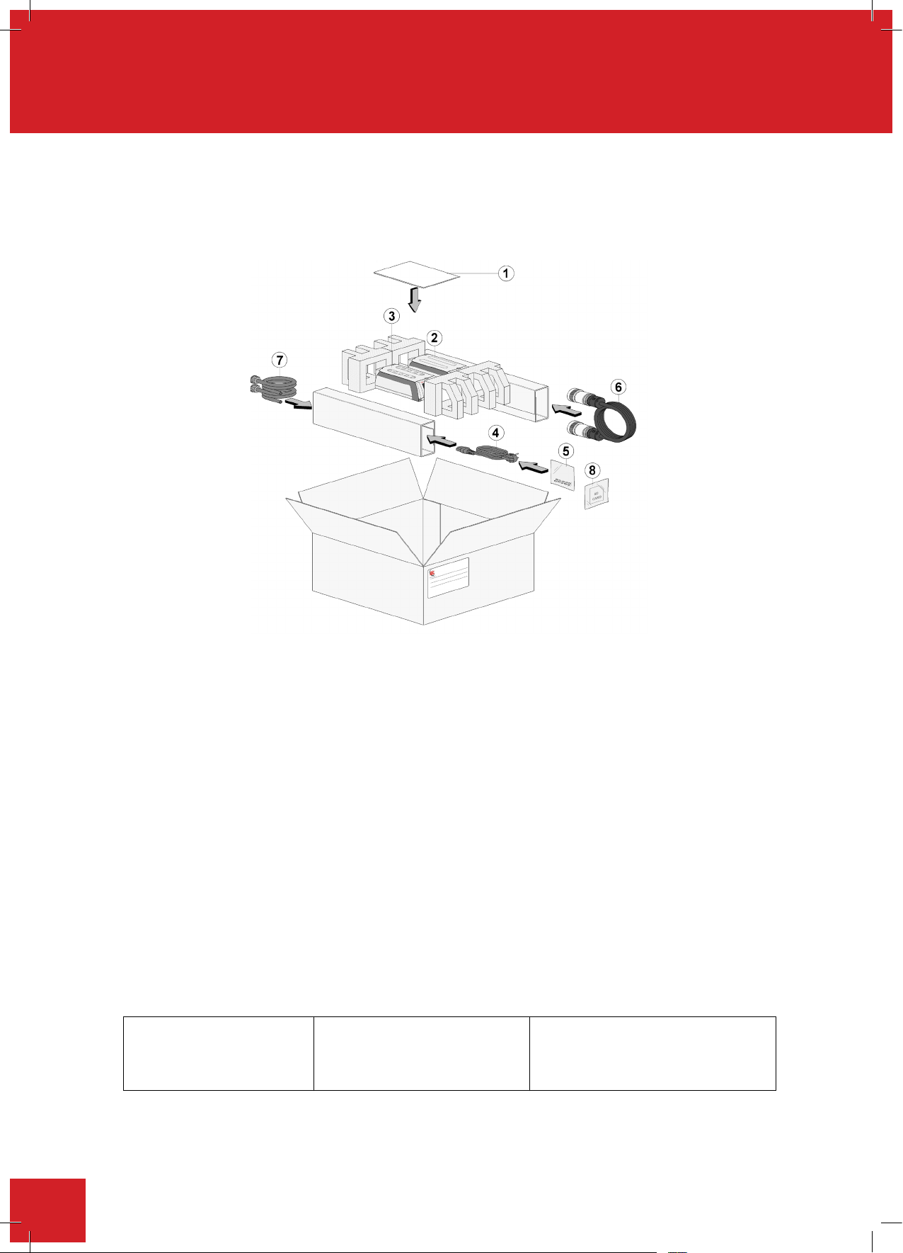
4.1. Please check the contents of your carton against the diagram.
For your future reference
Item
Description
Qty
1 Instruction book 1
2 Integrity 10 - PSU 1
3 Integrity 10 - UNIT 1
4 Mains cord and lead set
(illustration only)
A/R
5 Stir bars (x10) 1
6 Power cable assembly
(illustration only)
1
7 Coolant supply hoses 2
8 Programmed SD card –
Pre inserted in the unit.
1
Item
Description
Qty
4. Unpacking and contents
Please check the contents of your carton against the diagram.
For your future reference
please record your product’s
please record your products
Serial and Model numbers.
Serial and Model numbers
1 Instruction book 1
2 Integrity 10 - PSU 1
3 Integrity 10 - UNIT 1
4 Mains cord and lead set
(illustration only)
5 Stir bars (x10)
6 Power cable assembly
(illustration only)
7 Coolant supply hoses 2
8 Programmed SD card –
Pre inserted in the unit.
Unit Serial Number Unit Model/Cat Number
Unit Serial Number Unit Model/Cat Number.
A/R
2
1
1
22
Page 23

5. Installation
Electrical safety and installation
This equipment is designed to be used safely under the following conditions:-
• Indoor u
se only
• Use in a well ventilated area
• Altitude up to 2000 meters
• Ambient temperature range +5°C to +35°C
• Altitude to 2000m
• Relative humidity not exceeding 80% for temperatures up to 25°C decreasing linearly to 50%
relative humidity at 35°C
• Mains supply voltage fluctuations up to ± 10% of the nominal voltage
• Over-voltage category II IEC60364-4-443 applicable
• Pollution degree 2
• Use with a minimum distance all round of 200mm from walls or other items
The Power Supply Unit (PSU) for the Integrity 10 has been subjected to electrical safety testing as part of
the manufacturing process. However, it is acknowledged that some end users may wish to undertake
further electrical safety testing as part of the installation process.
AC dielectric withstand (Flash/Hi Pot) must not be undertaken on this equipment as damage may
Electrical safety and installation
This equipment is designed to be used safely under the following conditions:-
• Indoor u
se only
• Use in a well ventilated area
• Altitude up to 2000 meters
• Ambient temperature range +5°C to +35°C
• Altitude to 2000m
• Relative humidity not exceeding 80% for temperatures up to 25°C decreasing linearly to 50%
relative humidity at 35°C
• Mains supply voltage fluctuations up to ± 10% of the nominal voltage
• Over-voltage category II IEC60364-4-443 applicable
• Pollution degree 2
• Use with a minimum distance all round of 200mm from walls or other items
The Power Supply Unit (PSU) for the Integrity 10 has been subjected to electrical safety testing as part of
the manufacturing process. However, it is acknowledged that some end users may wish to undertake
further electrical safety testing as part of the installation process.
AC dielectric withstand (Flash/Hi Pot) must not be undertaken on this equipment as damage may
result. Such testing will invalidate warranty.
DC dielectric withstand (flash/Hi Pot) may be applied to the PSU only (i.e. The Integrity 10 unit must not
be connected when the PSU is being tested. The Integrity 10 unit operates at low voltage (15V DC) and
must not be subjected to dielectric withstand (Flash/Hi Pot) testing.
DC dielectric withstand (flash/Hi Pot) testing shall only be undertaken by competent trained personnel
using suitable test equipment / environment.
DC test voltage should be no more than 1.414 times normal AC test value for a class I (grounded)
equipment.
The test equipment/process should incorporate a discharge procedure to remove any stored DC charge
that may remain on the PSU.
This equipment must be earthed/grounded to a fixed earth/grounded mains socket outlet. The mains
Electrical safety and installation
This equipment is designed to be used safely under the following conditions:-
• Indoor u
se only
• Use in a well ventilated area
• Altitude up to 2000 meters
• Ambient temperature range +5°C to +35°C
• Altitude to 2000m
• Relative humidity not exceeding 80% for temperatures up to 25°C decreasing linearly to 50%
relative humidity at 35°C
• Mains supply voltage fluctuations up to ± 10% of the nominal voltage
• Over-voltage category II IEC60364-4-443 applicable
• Pollution degree 2
• Use with a minimum distance all round of 200mm from walls or other items
The Power Supply Unit (PSU) for the Integrity 10 has been subjected to electrical safety testing as part of
the manufacturing process. However, it is acknowledged that some end users may wish to undertake
further electrical safety testing as part of the installation process.
AC dielectric withstand (Flash/Hi Pot) must not be undertaken on this equipment as damage may
result. Such testing will invalidate warranty.
DC dielectric withstand (flash/Hi Pot) may be applied to the PSU only (i.e. The Integrity 10 unit must not
be connected when the PSU is being tested. The Integrity 10 unit operates at low voltage (15V DC) and
must not be subjected to dielectric withstand (Flash/Hi Pot) testing.
DC dielectric withstand (flash/Hi Pot) testing shall only be undertaken by competent trained personnel
using suitable test equipment / environment.
DC test voltage should be no more than 1.414 times normal AC test value for a class I (grounded)
equipment.
The test equipment/process should incorporate a discharge procedure to remove any stored DC charge
that may remain on the PSU.
This equipment must be earthed/grounded to a fixed earth/grounded mains socket outlet. The mains
supply is to be earthed/grounded in accordance with current international and local legislation as
applicable in the country/state of operation.
Ensure only the correct rated mains input fuses are fitted. (Where applicable ensure the correct Mains
cord and moulded IEC plug and lead set fuse if fitted). See Technical Specification, Section 8 of this
Instruction book.
Check the voltage on the product data label on this product unit and those of any accompanying electrical
accessory. Ensure the rating conforms to your local supply.
It is recommended this product should be connected to a mains supply source which incorporates an RCD
or GFCI device that has a tripping current of 30mA or less. The RCD or GFCI residual Current Device cuts
off power to the equipment immediately it detects a current leakage fault.
o not install this product or accessories on a surface which may become wet from use with
Electrical safety and installation
This equipment is designed to be used safely under the following conditions:-
• Indoor use only
• Use in a well ventilated area
• Altitude up to 2000 meters
• Ambient temperature range +5°C to +35°C
• Altitude to 2000m
• Relative humidity not exceeding 80% for temperatures up to 25°C decreasing linearly to 50%
relative humidity at 35°C
• Mainssupplyvoltageuctuationsupto±10%ofthenominalvoltage
• Over-voltage category II IEC60364-4-443 applicable
• Pollution degree 2
• Use with a minimum distance all round of 300mm from walls or other items
The Power Supply Unit (PSU) for the Integrity 10 has been subjected to electrical safety testing as part of
the manufacturing process. However, it is acknowledged that some end users may wish to undertake
further electrical safety testing as part of the installation process.
AC dielectric withstand (Flash/Hi Pot) must not be undertaken on this equipment as damage may
result. Such testing will invalidate warranty.
dielectricwithstand(ash/HiPot)maybeappliedtothePSU only (i.e. The Integrity 10 unit must not
DC
be connected when the PSU is being tested. The Integrity 10 unit operates at low voltage (15V DC) and
must not be subjected to dielectric withstand (Flash/Hi Pot) testing.
DCdielectricwithstand(ash/HiPot)testingshallonlybeundertakenbycompetenttrainedpersonnel
using suitable test equipment / environment.
DC test voltage should be no more than 1.414 times normal AC test value for a class I (grounded)
equipment.
The test equipment/process should incorporate a discharge procedure to remove any stored DC charge
that may remain on the PSU.
Thisequipmentmustbeearthed/groundedtoaxedearth/groundedmainssocketoutlet.Themains
supply is to be earthed/grounded in accordance with current international and local legislation as
applicable in the country/state of operation.
Ensureonlythecorrectratedmainsinputfusesaretted.(WhereapplicableensurethecorrectMains
cordandmouldedIECplugandleadsetfuseiftted).SeeTechnicalSpecication,Section10ofthis
Instruction manual.
Check the voltage on the product data label on this product unit and those of any accompanying electrical
accessory. Ensure the rating conforms to your local supply.
It is recommended this product should be connected to a mains supply source which incorporates an RCD
or GFCI device that has a tripping current of 30mA or less. The RCD or GFCI residual Current Device cuts
off power to the equipment immediately it detects a current leakage fault.
Do not install this product or accessories on a surface which may become wet from use with
other equipment.
The unit is supplied with a Mains cord and moulded plug wired as follows.
Green/Yellow or Green = Earth/Ground
Blue or White = Neutral
Brown or Black = Live/line hot.
23
Page 24
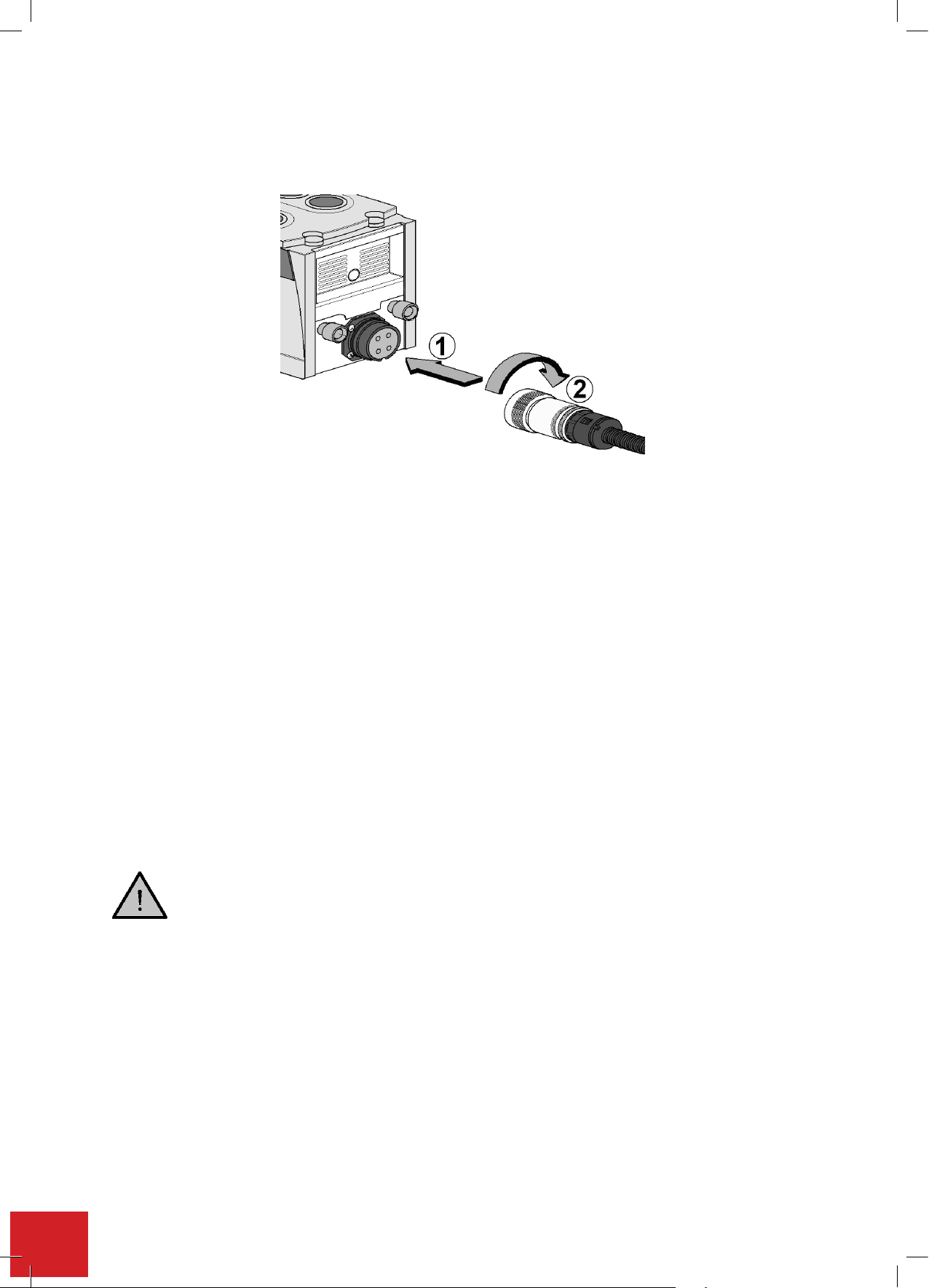
Connect the power cable between the Integrity 10 PSU and the Integrity 10 unit. Push the plug into the socket
White
=
Neutral
Black
=
Live/line hot.
. Repeat the process for
Green/Yellow
or Green = Earth/Ground
Blue
or
White
=
Neutral
Brown
or
Black
=
Live/line hot.
Connect the power cable bet
ween the Integrity 10 PSU and the Integrity 10 unit. Push the plug into the
socket ensuring the lugs engage
and twist the lock ring clockwise to secure
. Repeat the process for
attaching the other end of the power cable to the PSU.
Connect the coolant supply to the Integrity 10 unit ensuring the supply outlet feeds the indicated reaction
block inlet and the return is connected to the indicated outlet. Turn on the coolant supply and check there
are no signs of any water leaks around the connectors. (Turn off the chilled water supply after checking for
leaks).
To ensure efficient heating and cooling, the Integrity cell design incorporates high quality copper heat sink components that
ensure optimum heat transfer between the process and the cooling media.
When good quality coolant water is used, no service problems will be experienced associated with internal corrosion or
blockages. However, if coolant water is deficient (e.g. hard water, high oxygen content, turbid, contaminated, debris, etc. and
this results in the internal corrosion, or blockage of the cooling system, then this is beyond the control of the equipment
manufacturer. As such Bibby Scientific Limited cannot support warranty claims for blockages, corroded cells etc. that are
attributable to poor quality coolant water.
To guard against poor water quality and its affects, the following recommendations are made.
1. At installation, the end user should ensure that the cooling water supply is of distilled water quality.
2. Additives are not recommended
3. A coolant inline filter is recommended to filter to 75 micron. This should be checked / cleaned at intervals to suit local
operating conditions.
4. Minimal annual service check by Bibby Scientific Limited, or its designated service agent, is recommend which
includes flushing/back flushing/removal and inspection of cell conditions for any early signs of coolant water
problems.
Note: The chilled water flow rate through this equipment must be continuous at minimum rate of 2.5 litres/min at 5
The coolant system should be able to dissipate heat energy at 1100W with a coolant temperature of 5
°°°°
C. Running all 10
cell positions at -25
°°°°
without a chilled water set at 5
°°°°
C supply may cause stress on the electrical components and
result in a reduced performance which may result in shorter service intervals.
For temperatures below 5°C, or as
recommended in the chiller manual, a coolant must be used. A mix
of 1:1 laboratory grade ethylene glycol and water is recommended. DO NOT use deionised water.
WARNING:
ensuring the lugs engage 1 and twist the lock ring clockwise to secure 2. Repeat the process for attaching the
other end of the power cable to the PSU.
Connect the coolant supply to the Integrity 10 unit ensuring the supply outlet feeds the indicated reaction block
inlet and the return is connected to the indicated outlet. Turn on the coolant supply and check there are no signs
of any water leaks around the connectors. (Turn off the chilled water supply after checking for leaks).
To ensure efcient heating and cooling, the Integrity cell design incorporates high quality copper heat sink components that ensure
optimum heat transfer between the process and the cooling media.
When good quality coolant water is used, no service problems will be experienced associated with internal corrosion or blockages.
However, if coolant water is decient (e.g. hard water, high oxygen content, turbid, contaminated, debris, etc. and this results in the
internal corrosion, or blockage of the cooling system, then this is beyond the control of the equipment manufacturer. As such ColeParmer Limited cannot support warranty claims for blockages, corroded cells etc. that are attributable to poor quality coolant water.
To guard against poor water quality and its affects, the following recommendations are made.
1. At installation, the end user should ensure that the cooling water supply is of distilled water quality.
2. Additives are not recommended
3. A coolant inline lter is
to suit local operating conditions.
4.
Minimal annual service check by Cole-Parmer Limited, or its designated service agent, is recommended
which includes ushing/back ushing/removal and inspection of cell conditions for any early signs of
coolant water problems.
See Appendix 'A'. Integrity cooling guide for more information
For temperatures below 5°C, or as recommended in the chiller manual, a coolant must be used. A mix
of 1:1 laboratory grade ethylene glycol and water is recommended. DO NOT use deionised water.
recommended to filter to 50 micron. This should be checked / cleaned at intervals
24
Operating pressure up to 2.0bar - Maximum safe pressure 4.5bar.
WARNING:
•Donotuseammablecoolants.
•Consultthechillermanualtoensureacompatibleuidisused.
•Theuidmustbecompatiblewiththeincubator’swettedpartswhicharecopper,stainless303,
aluminium and nitrile.
• Ensure all tubing is kept free of kinks and restrictions and is held tidily in place using tie wraps if
necessary.
Page 25

(For PC connection only) Connect a USB data cable between the host PC and the Integrity 10 unit as
illustrated.
Connect the PSU to the mains supply using the plug and lead set supplied with the Integrity. Turn on the mains
power supplying the PSU.
25
Page 26

6. Environmental protection
Electrothermal has given due consideration to environmental issues within the design and manufacturing
process of this product without compromising product performance and value.
Packaging materials have been selected such that they may be sorted for recycling.
Electrothermal has given due consideration to environmental issues within the design and manufacturing
process of this product without compromising product performance and value.
Packaging materials have been selected such that they may be sorted for recycling.
At the end of your product and accessories life, it must not be discarded as domestic waste. Ref: EU
Packaging materials have been selected such that they may be sorted for recycling.
This product and accessories must be accompanied by a completed Decontamination
Packaging materials have been selected such that they may be sorted for recycling.
This product and accessories must be accompanied by a completed Decontamination
Certificate prior to any disposal. Copies of the Certificate are available from your distributor of
Electrothermal products, alternatively you may copy and enlarge from ‘Appendix A’ of this
instruction book.
This product contains a Lithium Cell button Battery (CR2032) on the control PCB
Electrothermal has given due consideration to environmental issues within the design and manufacturing process
of this product without compromising product performance and value.
Packaging materials have been selected such that they may be sorted for recycling.
At the end of your product and accessories life, it must not be discarded as domestic waste. Ref: EU
Directive 2002/96/EC on Waste Electrical and Electronic Equipment Directive (WEEE).
*Please contact your distributor / supplier for further information.
For end users outside of the EU consult applicable regulations.
This product should only be dismantled for recycling by an authorised recycling company.
This product and accessories must be accompanied by a completed Decontamination Certificate
prior to any disposal. Copiesofthecertificateareavailablefrom distributor/Manufacturer.
6.1. Battery disposal
This product contains a Lithium Cell button Battery (CR2032) on the control PCB located in
the front Pod of the Integrity 10 Unit. All batteries must be disposed of in accordance with
regulations. DO NOT dispose of product in a fire as batteries may explode.
Cole-Parmer’s Electrothermal branded product range is registered with the Environment Agency under the name
of as Electrothermal Engineering Limited as being a producer of WEEE (Waste Electronic and Electrical Equipment)
through b2b Compliance, an authorised waste collection compliance scheme.
26
Page 27
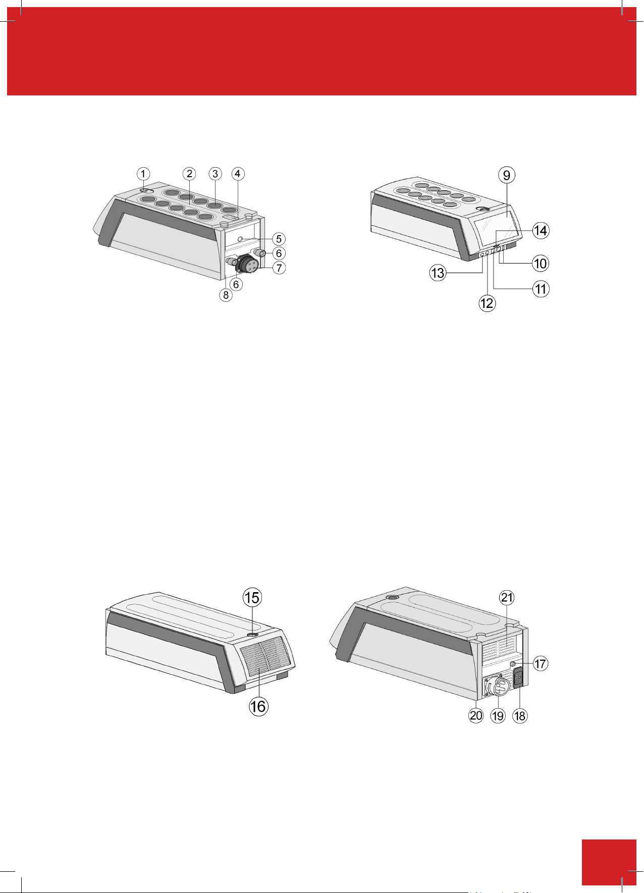
7. Product operation
7.0.
PRODUCT OPERATION
7.1. Product overview
The illustrations below show a detailed layout of the product.
7.1. Product overview
The illustrations below show a detailed layout of the product.
Integrity 10 Unit
Integrity 10 Unit
1 Latch – drip tray release
2 Drip tray
3 Reaction well
4 Refer to Instruction book warning
5 Bus socket (for driving accessories)
6 In / out coolant water supply
7
Plug for power cable
8 Data plate label – found on underside of the reaction unit
9 Touch sensitive screen
10 USB ports (Master and Slave)
11 Ethernet RJ45 Socket
12 GSIOC protocol socket
13 RS232 / 485 protocol socket
14 SD card slot
Power supply overview
On / Off (standby) button
15
16 Front grill – cooling vents
17 Earth test point
18 IEC mains input socket
19
Socket for power cable
20 Data plate label – found on underside of the PSU unit
21 Cooling vents
27
Page 28
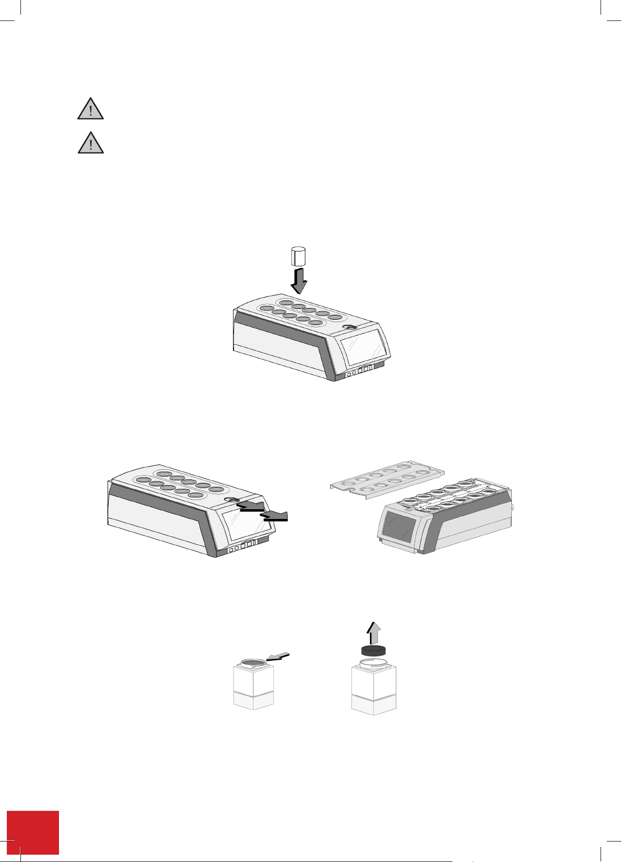
7
15
On / Off button switch
16
Front grill – cooling vents
17
Earth test point
18
IEC mains input socket
19
4 pin socket for power cable
20
Data plate label – found on underside of the PSU unit
21
Cooling vents
7.2. Reduction Sleeves - Fitting and Removal
Always ensure the cell temperatures are at a safe temperature to touch. (Between 40°C and -
15
On / Off button switch
16
Front grill – cooling vents
17
Earth test point
18
IEC mains input socket
19
4 pin socket for power cable
20
Data plate label – found on underside of the PSU unit
21
Cooling vents
7.2. Reduction Sleeves - Fitting and Removal
Always ensure the cell temperatures are at a safe temperature to touch. (Between 40°C and -
Reductionsleev
.2.
es - fittingandremoval
Always ensure the cell temperatures are at a safe temperature to touch. (Between 40°C and -5°C)
Always turn off the coolant water supply before removing the drip tray.
Insert reduction sleeve
Insertreduction sleeves by pushing them straight intothe cells. Reduction sleeves may be tted into any cell
position.
Remove reduction sleeve
To remove the reduction sleeves, release the latch on the top of the Integrity unit and lift off the drip tray.
Push in the oil seal retention clip and lift out oil seal.
28
Page 29
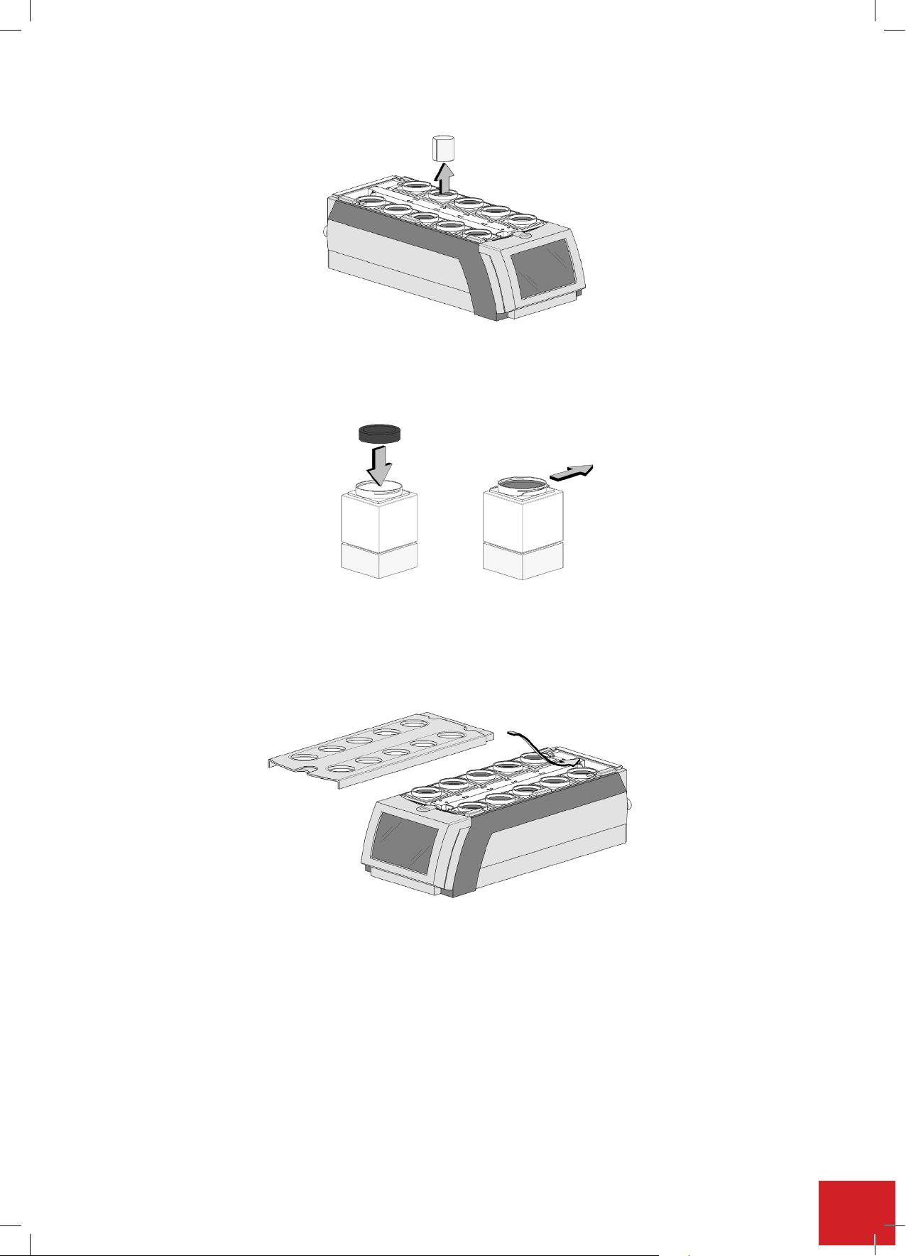
Lift reduction sleeves out of cells.
Replace the oil seal and reposition the retention clip.
Replace the drip tray ensuring the latch is engaged properly.
29
Page 30
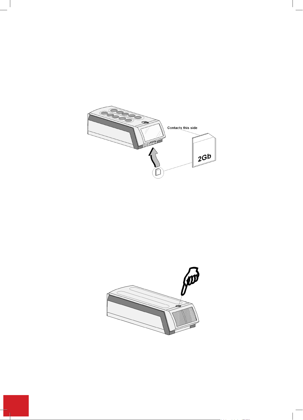
7.3. Insert SD card
Note: Your Integrity 10 unit will have been
not function without it fitted.
Insert the SD card supplied into the SD card slot, with the card contacts facing the back. Leave the SD card in
place during use. The SD card is acting as the system hard drive.
Note: Your SD card has been programmed for use specically with the Integrity system for which it was supplied.
If the card is swapped with another SD card programmed for use with another integrity system the touch screen
buttons may not align with the screen touch sensing points.
Observe the correct orientation of the SD card.
DO NOT r
corruption may result.
emove the SD
card
when
despatched with the card already in position. Your Integrity unit will
the
unit
powered up or operating. Loss of data and program
is
7.4. Turn unit ON
Note: Ice will form round the Integrity 10 cell assemblies when the unit is run for extended periods at temperatures
below 0°C .
Ensure coolant supply and mains power are connected and turned on. See Appendix 'A'. Integrity
cooling guide for the cooling specification. Make sure to turn the water on before turning on the power. If
this is not done an error message may appear.
Press the button on top of the Power Supply Unit to commence operation. Observe the green luminance of the
power on switch.
The Integrity 10 can be used in conjunction with STEM Integrity control software (ATS11005), or it can be run
in standalone mode. InstandalonemodetheIntegrity10canbesetupandrunviamanualcontrolorviaa
profileset-up.
30
7.5. Turn unit OFF
Depress the Power Supply button once again to turn off the unit.
Page 31
7.6. Power up
Typical splash screen for the Integrity 10 Unit.
WhentheIntegrity10isrstpoweredupitwillgothroughaselfcheckandwarmupcyclewhichwilltakeafew
minutes. During this time period a splash screen will be displayed.
After the Splash screen has been displayed the home screen will come into view.
Typical splash screen for the Integrity 10 Unit.
Home screen for the Integrity 10
31
Page 32
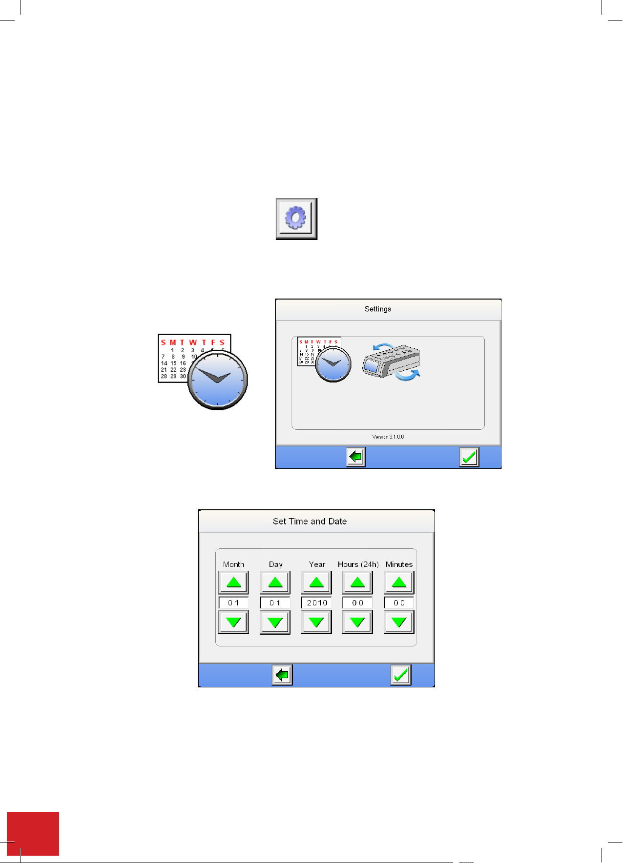
7.7. Time and date setting
7.7. Clock and Date Setting
The first time the Integrity 10 system is used the time clock and date must be set. The clock and date
setting is performed using the following method.
Note: Accurate clock time is required when using data storage facility as the experiment data stored is
time stamped.
Touch the settings Icon to enter settings mode.
Note: Settings mode cannot be accessed if any cell positions are in use.
Touch the clock Icon to enter the clock and date settings mode.
Clock Icon
7.7. Clock and Date Setting
The first time the Integrity 10 system is used the time clock and date must be set. The clock and date
setting is performed using the following method.
Note: Accurate clock time is required when using data storage facility as the experiment data stored is
time stamped.
Touch the settings Icon to enter settings mode.
Note: Settings mode cannot be accessed if any cell positions are in use.
Touch the clock Icon to enter the clock and date settings mode.
From the clock setting screen use the up/down arrowed buttons to set the correct time and date.
Clock Icon
ThersttimetheIntegrity10systemisusedthetimeclockanddatemustbeset.Thetimeanddatesettingis
performed using the following method.
Note: Accurate clock time is required when using data storage facility as the experiment data stored is time
stamped.
Touch the settings Icon to enter settings mode.
Note: Settings mode cannot be accessed
if any cell positions are in use.
Touch the clock Icon to enter the clock and date settings mode.
Clock icon
From the clock setting screen use the up/down arrowed buttons to set the correct time and date.
Once the correct date and time has been entered press the Green tick button to accept the setting entered.
You are now taken back to the home screen from which you commence operation.
32
Page 33
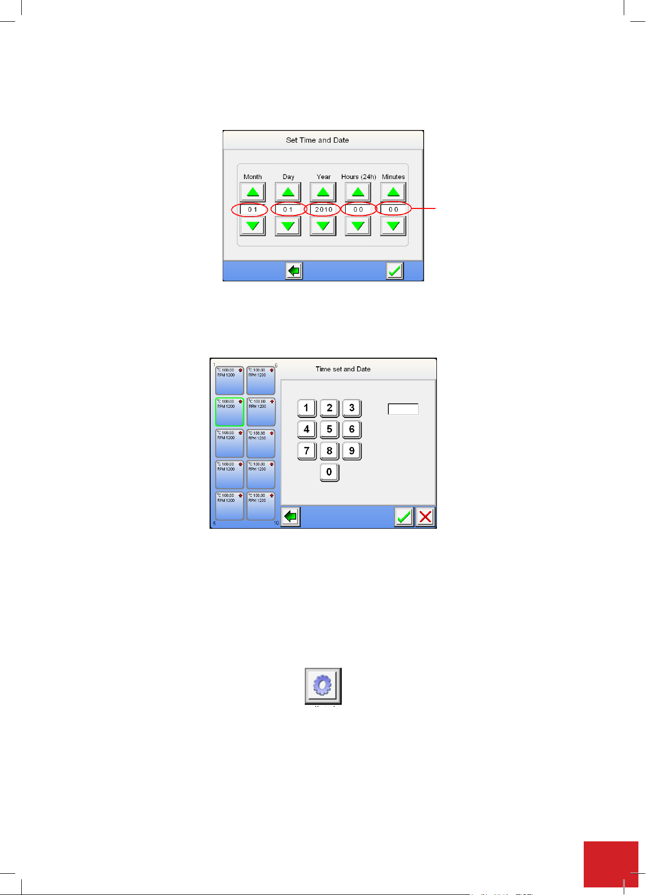
ALTERNATIVE METHOD
Touchthedisplayeldyouwishtoset.
Display Field
Select the setting required from the touch pad screen. Touch the green tick to except the setting or touch the
redcrosstocleartheeldandre-entertheeldsetting.Thegreenbackarrowwilltakeyoubacktotheprevious
screen.
Note: Daylight saving time settings will need to be adjusted using the time setting process as described above.
Note: The date will automatically adjust for leap years.
7.8. Communication protocol selection (for use with external control)
To change the protocol to accept GSIOC ensure your host systems communication platforms protocol is GSIOC
driven.
Touch the settings Icon to enter settings mode.
Note: Settings mode can only be entered immediately after the Integrity has been switched on.
Once run settings have been made the settings icon will disappear.
To enter ‘settings mode’ at any time ensure all cells are turned off.
Touch the communication Icon in the settings screen to enter communication selection.
Note:
GSIOC mode must be selected to control via ATS11005 Integrity software.
33
Page 34
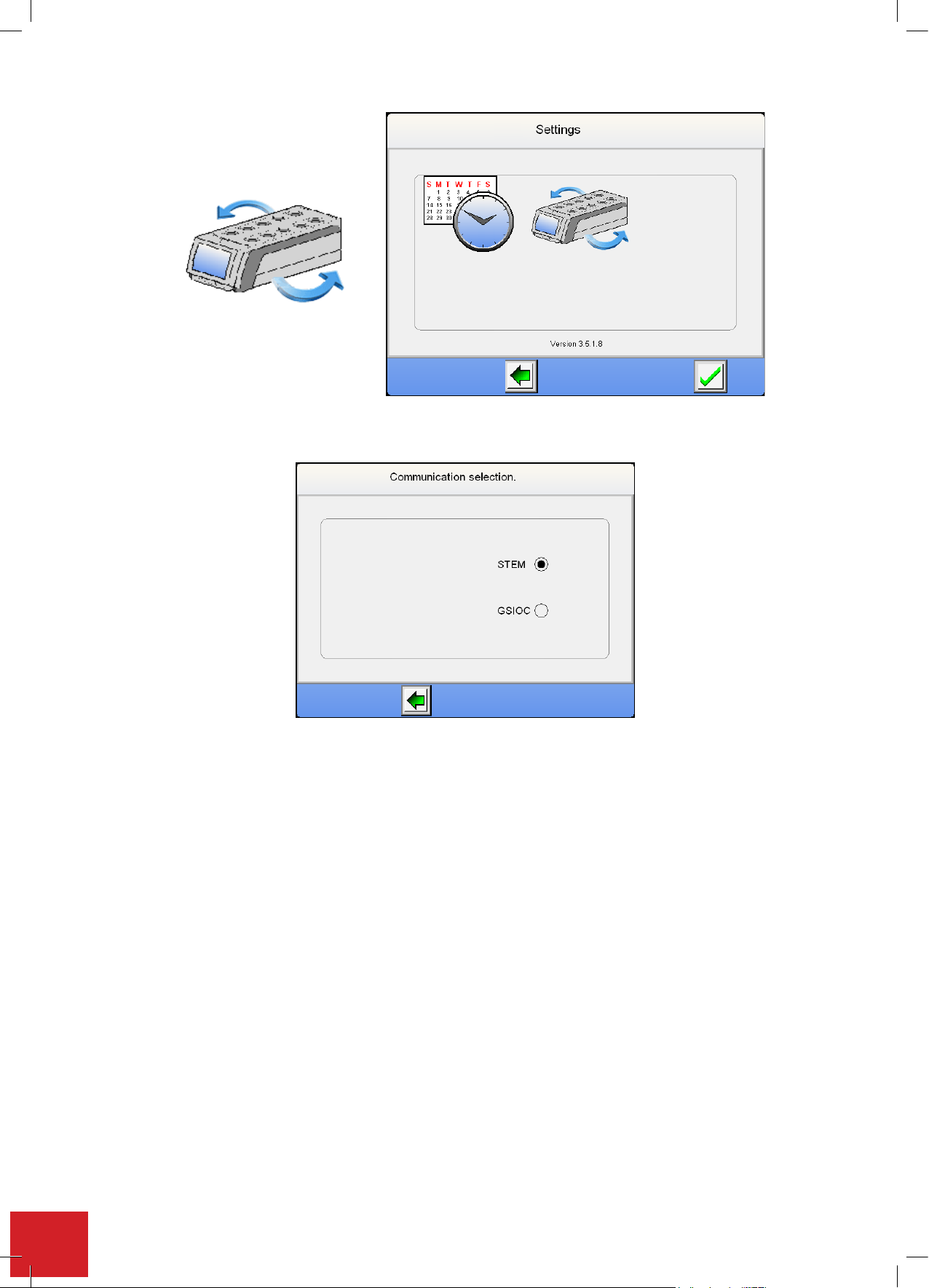
Communication icon
Communication icon
From selection screen touch the GSIOC facility selection.
Once th
From se
e settings protocol has been changed the Integrity 10 must
lection screen touch the GSIOC facility selection.
be switched off and then turned back on
before the new settings will become active.
Unless using this equipment with GSIOC protocol enabled systems leave the communication protocol set for STEM.
7
From the home screen touch the settings Icon to access the settings screen.
is
To check you have the latest software version, please contact [email protected].
34
.9.
iewfirmwarereleaseset
V
displayed across the bottom of the settings screen.
The software version set number
Page 35
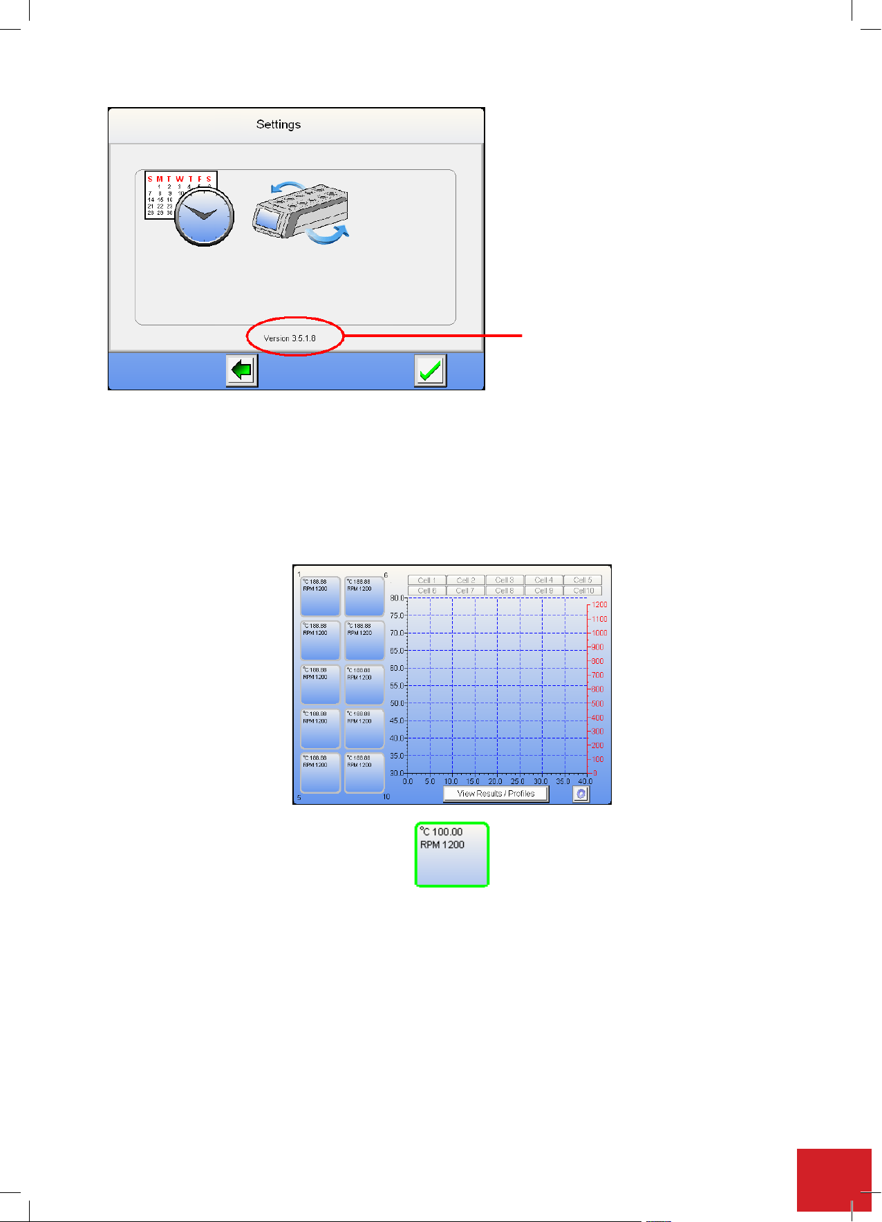
Press the green back arrow to return to the home menu.
the green back arrow to return to the home menu.
7.10. Manual control
This view of the Home Screen is typical of the Integrity 10 without any cell position operational.
The graph area will represent real time data when the unit is running.
Version number
A highlighted cell button showing real time temperature and stir speed
Individual cell adjustment and settings: By touching any one of the cell position buttons the correlating cell
canbesettoruninmanualcontrolorprolemodeasdeterminedbytheuser.
TheuserisnowpromptedtoselectwhethertheywishtoruntheIntegrity10in‘ManualControl’or‘ProfileMode’.
Select ‘Manual Control’ by lightly touching the button position on the touch screen panel.
35
Page 36
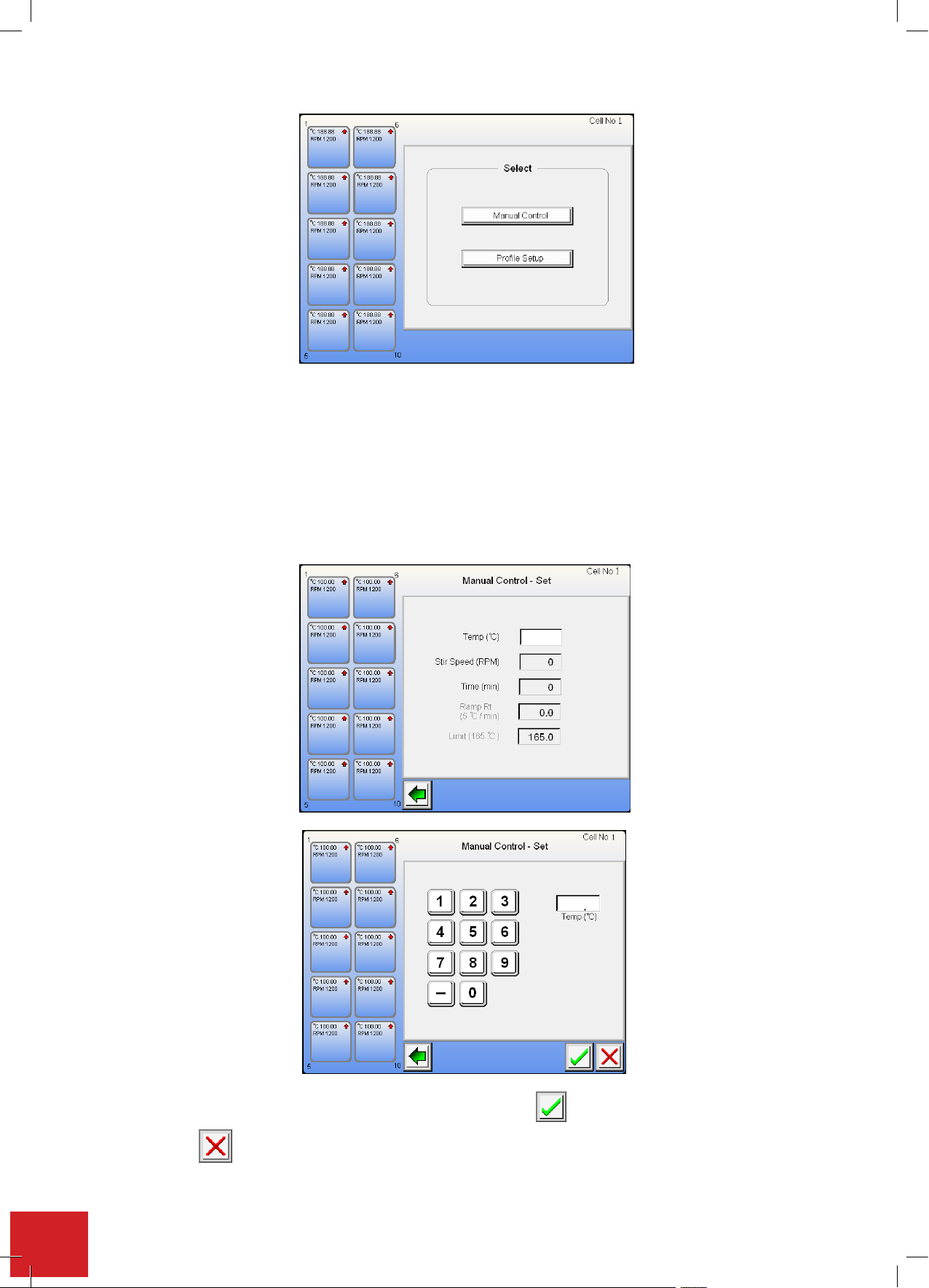
T
button to accept the value
button will remove the setting entered in that field.
hetemperature field must be filled however all other fields are optional.
Greyedouteldsindicateanoptionalsetting.
7.10.1. Setting the temperature
Touchtheeldboxonthe display screen to enter asettingintothe appropriate eld. Toenter a temperature
setting,touchthetemperatureeldbox.
Use the keypad to enter the required temperature setting. Press the button to accept the value entered.
Touchingthebuttonwillremovethesettingenteredinthateld.
36
Page 37
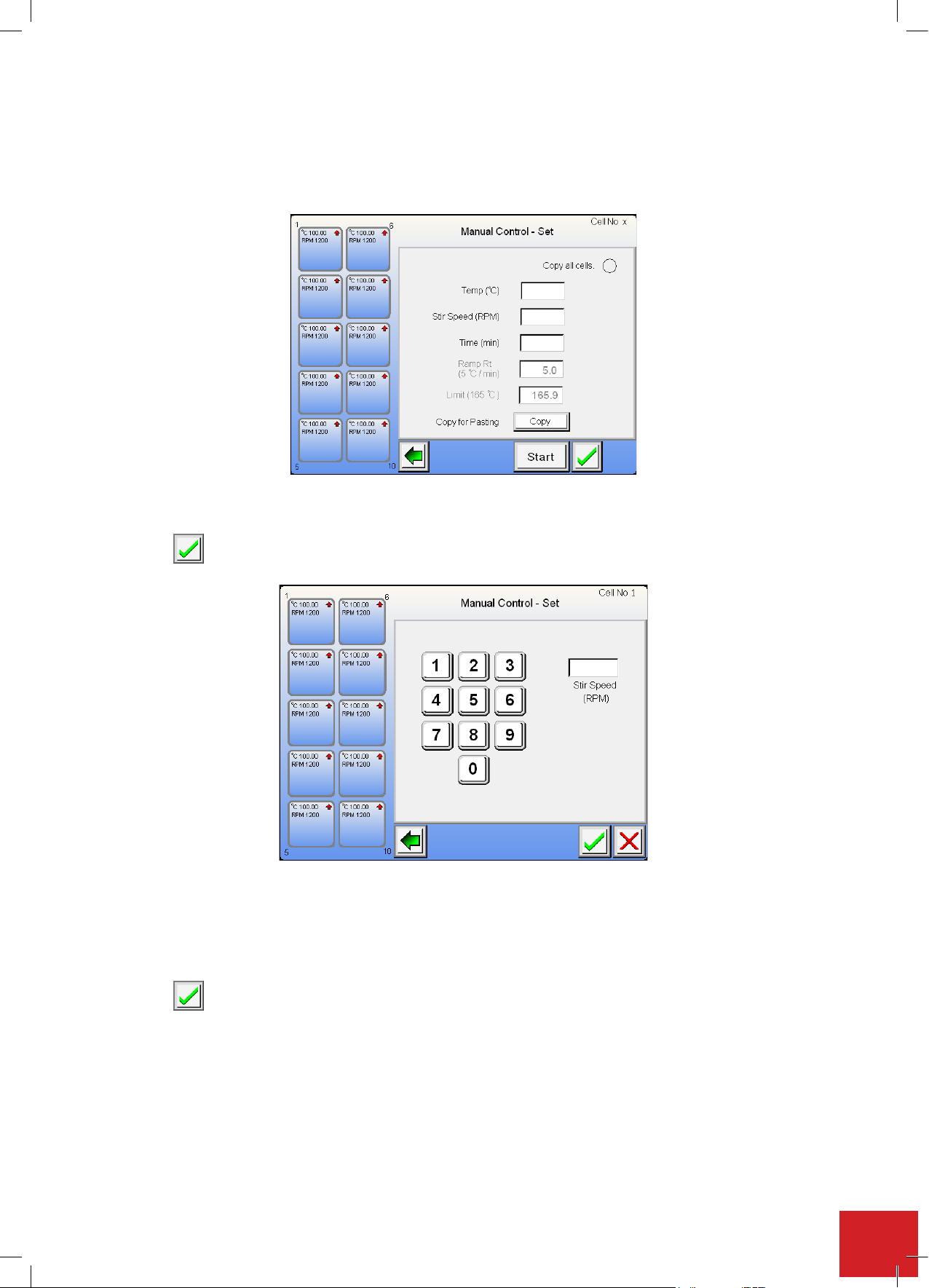
Note: When a temperature value has been entered both Ramp rate and Upper limit elds may be selected.
button to accept the value entered.
button to accept the value entered.
7.10.2. Setting the stir speed:
TouchtheStirspeedeld.
As with the process for entering a temperature you may enter the stir speed using the key pad.
Press the button to accept the value entered.
7.10.3. Setting the run time
Thelengthoftimetheuserwishestheunittorunthecellforissetviathiseld.Bytouchingthe‘Time’elda
run time period may be set. Enter the required run time in minutes. Example, 4 hours 25 minutes is 265 minutes.
Note: The maximum run time entry is 9999 minutes = 166 hours and 39 minutes.
Press the button to accept the value entered.
7.10.4. Setting the ramp rate
TheoptionaleldofRampratemaybechangedusingthesameprocedure.Touchtheeldboxtoselectthe
setting keypad.
Note: The default setting for ramp rate is 5.0°C per minute. Graduations can be set as low as 0.1°C per minute.
When
0.0 is entered, maximum ramp rate is achieved as default, however, this is uncontrolled ramping.
37
Page 38
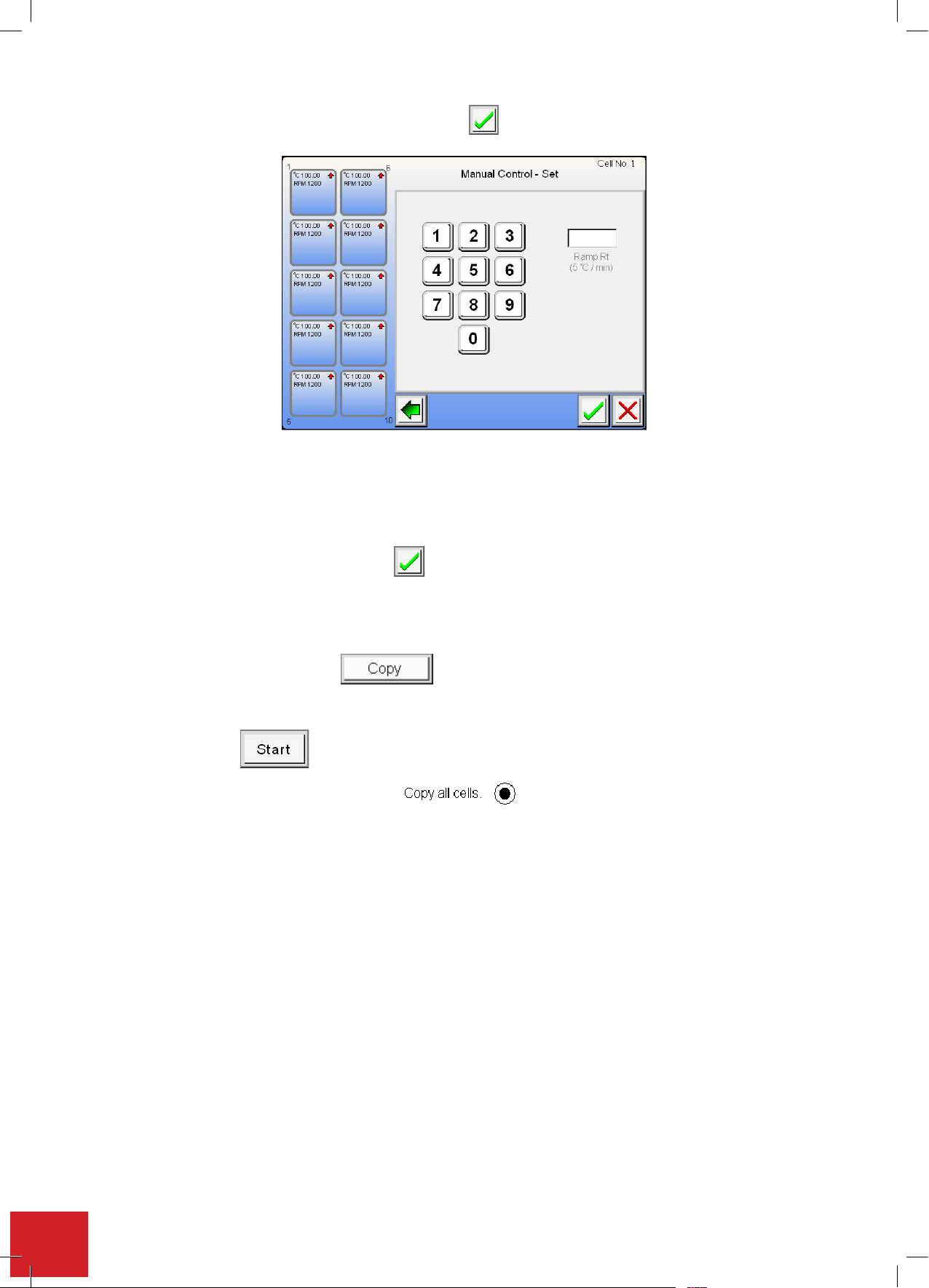
Enter the required ramp rate using the keypad. Press the button to accept the value entered.
button to accept the value entered.
. The cell will commence running as per the inputted settings.
and selecting the green tick all the
button to accept the value entered.
7.10.5. Setting the maximum upper limit
To help control an exothermic reaction a maximum upper temperature limit may be set. When the Integrity 10
senses an unexpected change in temperature state, action will be taken to prevent the change exceeding the set
maximumtemperaturelimit.Thesetdefaultofthiseldis165.0°C.
Enter the setting using the keypad. Press the button to accept the value entered.
7.10.6. Copy function
Oncetheuserhascompletedenteringalltherequiredeldentriestheenteredsettingsmaybecopiedoverinto
another cell. Touch the copy button to write the settings to the internal clipboard.
Pressingbackwillnowshowthehomescreen.Touchthecellyouwishtopastethevalueintoandtheeldswill
havethecopiedvaluelledin.
You may now press The cell will commence running as per the inputted settings.
Copy all: By selecting the copy all check spot and selecting the green tick all the
setting made are automatically copied into all the other vacant cell positions.
If ‘copy all cells’ is selected pressing ‘start’ will cause all cells to commence operation. The home screen
is then displayed.
Note: The Paste button is only visible once the copy button has been selected.
38
Page 39
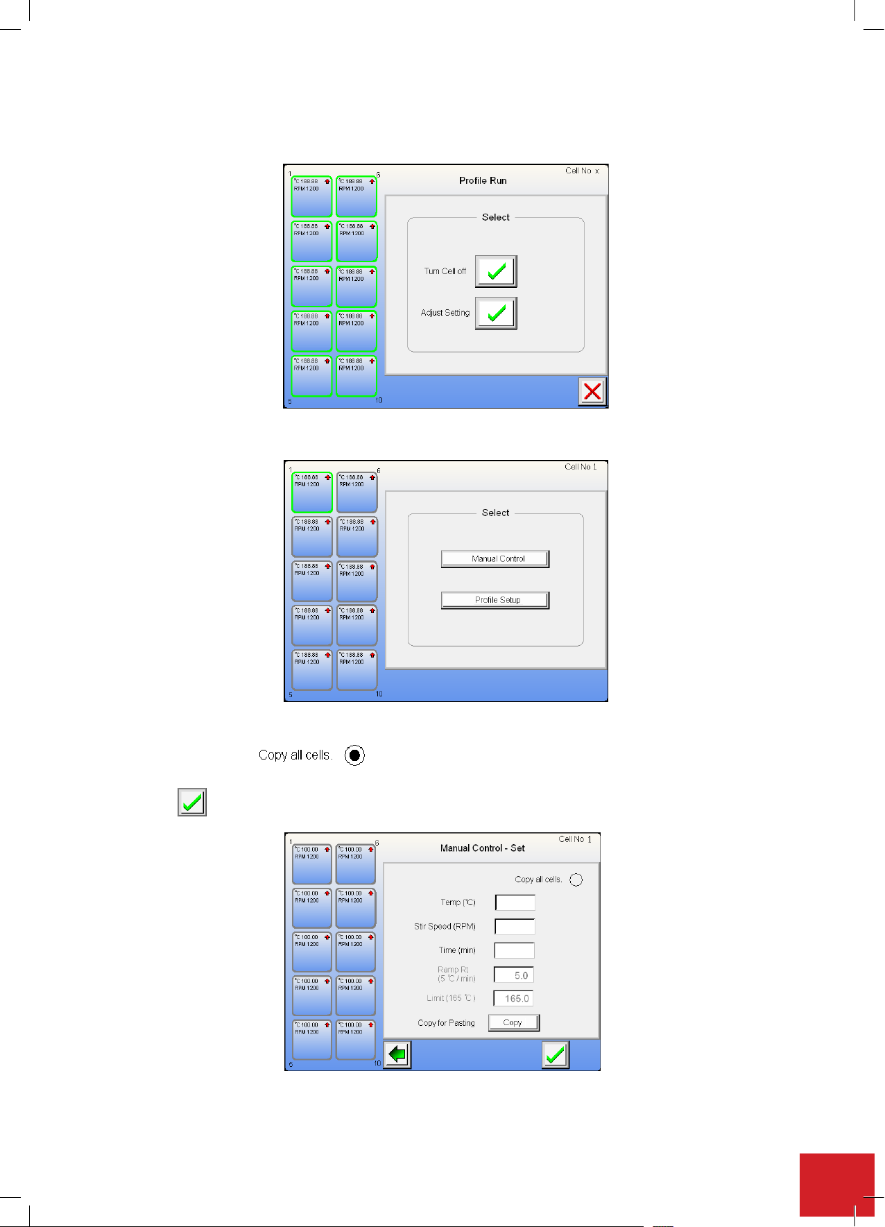
7.10.7. Adjusting the settings of a running cell in manual control
and selecting the green tick all the
button to accept the value entered.
Touch the active cell button for adjustment. The screen will ask you to ‘Turn cell off’ or ‘Adjust setting’.
Touch the adjust button and then select the ‘Manual control’ from the next screen.
Selecttheeldoreldstobeadjustedaspertheoriginalrunsetup.
Check the ‘All cells’ spot if you wish to apply the change to all cells, or touch the copy button
for pasting the change into selected other cells.
Touch the button to accept and commence running the change.
Note: The ‘Start’ button isn’t visible when adjusting a running cell
39
Page 40
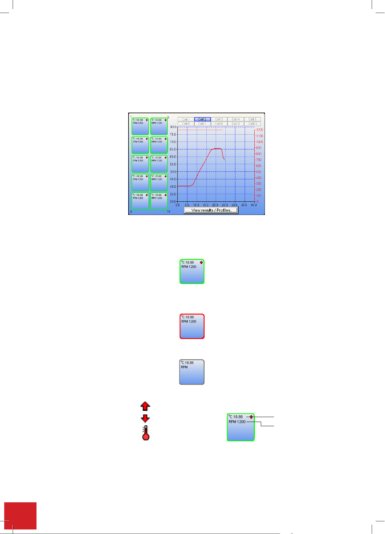
7.10.8. Home screen when operational
Cell temperature increase.
Cell temperature increase.
Cell tem
perature decrease.
Cell temperature increase.
Cell tem
perature decrease.
Control
by contents
Shown in this example is a typical home screen with all the cells operational. The graph on display is from cell 2.
To change the graph view between cells, touch the cell number at the top of the graph.
Note: If a cell is not operational it will not be possible to select the tab.
By touching the graph screen area it is possible to toggle sequentially from one screen to the next operational
screen in ascending order.
The graph is accumulative and will auto rescale as a cell is run.
When a green band is seen around the cell, this indicates the cell has a setting written to the field(s). The cell may not
be running but it has been set ready for operation.
Aredbandaroundthecellindicatesthecellhasnishedarunandassociatedactivitiesarecomplete.Seesection
7.14‘SavinganExperiment’.Oncethecellhasfinished,the
cell can be used again.
A grey band indicates that the cell is not in use and that no data is sitting behind awaiting a storage decision.
On screen symbols
experimentmustbeeithersavedordeletedbeforethe
The real time temperature and stir speed are shown within the cell box.
40
Cell temperature increase.
Cell temperature decrease.
Control by contents
Temperature °C
Stir speed RPM
Page 41
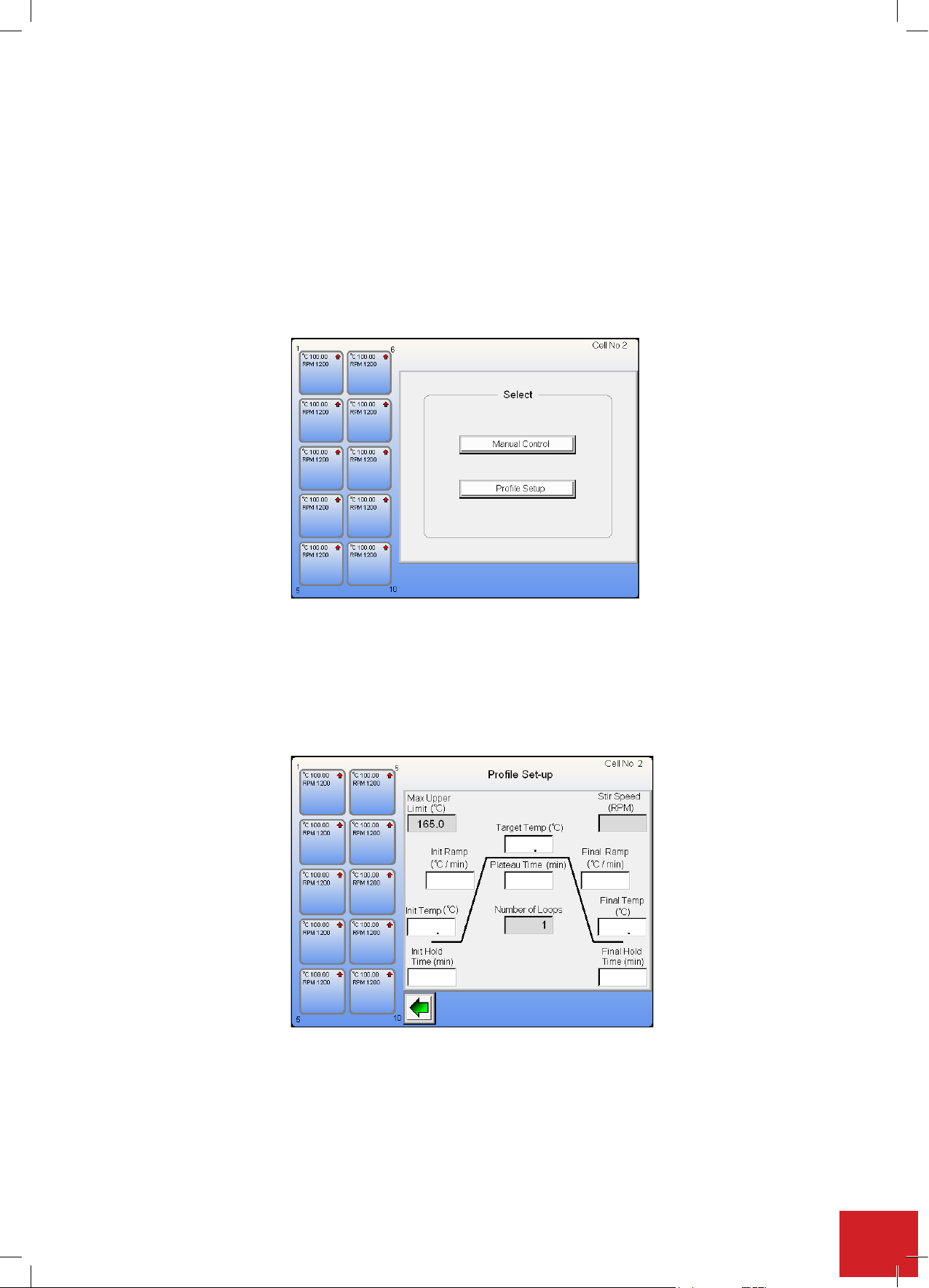
7.11. Profile control
and if required repeat that same cycle as
and if required repeat that same cycle as
Note: It is possible to have some cells running in prole mode while others are running via manual control.
Aprolewillallowtheusertosetupandrunastepcycleandifrequiredrepeatthatsamecycleasmanyas10
times (when using the optional Integrity PC software this is increased to 999 times).
7.11.1. Profile set up
Fromthehomescreen,touchtherequiredcelltheproleistobesetupin.
Thistimeselectthe‘Prolesetup’button.
This next screen shows a prole step. To complete the prole all elds must be completed. Once a eld has
changed from a grey state it can have setting parameters added and amended. The screen layout is intended to
visiblyshowthestepsrequiredtocompleteaprolesetup.
Note: It is possible to set up a profile that is the inverse of the one displayed by selecting a target
temperature below that of the initial temperature.
41
Page 42
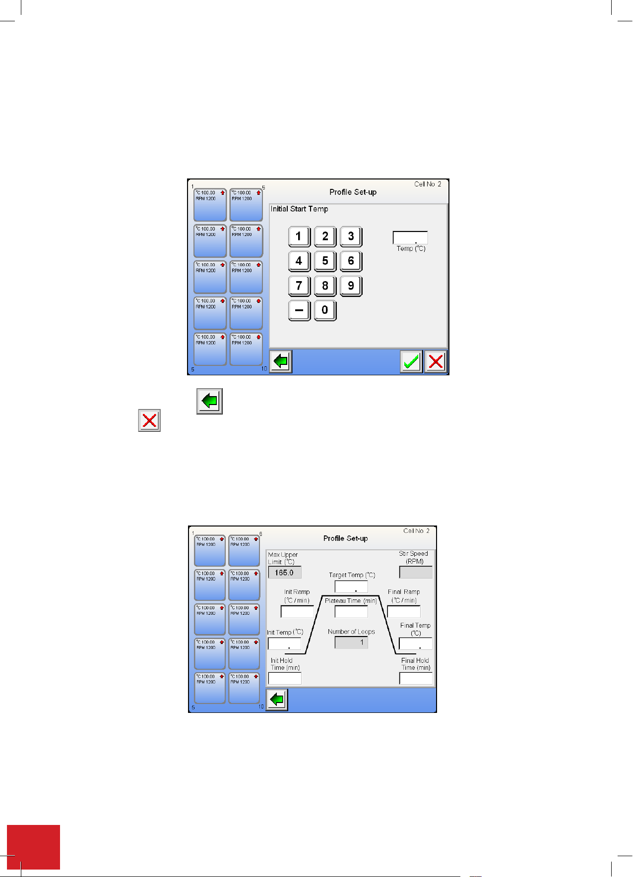
7.11.2. Setting the initial temperature
ual control the will take you back to the previous screen. The button is
ill take you back to the previous screen. The button is
s used to remove an incorrect field entry. Use the keypad
Touchtheinitialtemperatureeldtoactivatetheeldinputscreen.Usethekeypadtoinputyourrequiredstart
temperature.Theinitialstarttemperatureisthetemperatureyouwishtheproletocommencefrom.Itcanbe
different to the ambient temperature of the cell.
Note: To enter -25.6°C Press 2, then 5, then 6, followed by the minus sign.
Note: the - minus symbol will only appear when you start entering the temperature.
As with manual control the will take you back to the previous screen. The button is used to accept a
valueandthe is used to remove an incorrect field entry. Use the keypad to enter your initial start
temperature.
7.11.3. Setting the initial hold time
Thisissimilarinoperationtothepreviouseld.Touchtheeldtoentertherequiredsetting.Allwhiteeldboxes
musthaveavalueentered.Greyeldboxesareoptionalsettingsanddonotneedtohaveasettingentered.
Use the keypad to enter the time value (minutes) for the length of time you wish the initial temperature to be held
at.
Note: Enter the time in minutes. Example, 4 hours 25 minutes is 265 minutes.
42
Page 43
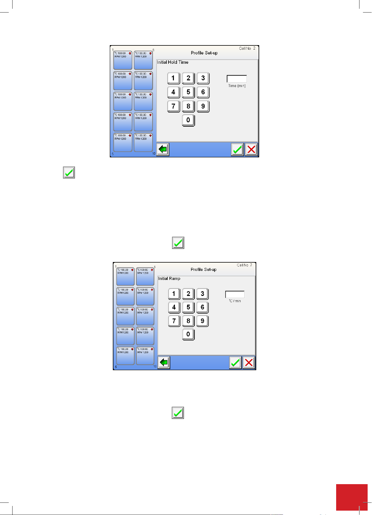
Touch
Touc
h to except the time entered in the Initial hold time field.
7.11.4. Setting the Initial Ramp: The initial ramp rate is the rate of temperature change required.
The Initial ramp may be set to decrease in temperature as well as increase. Touch the field to
enter the required setting.
Note: The default setting for ramp rate is 5.0°C per minute. Graduations can be set as low
as 0.1°C per minute. When 0.0 is entered the ramp rate will climb as rapidly as
possible to the desired target temperature.
Use the keypad to make the field entry. Touch the button to accept the value set.
button to accept the value entered.
button to accept the value entered.
button to accept the value entered.
7.11.4. Setting the initial ramp
The initial ramp rate is the rate of temperature change required. The initial ramp may be set to decrease in tem-
peratureaswellasincrease.Touchtheeldtoentertherequiredsetting.
Note: The default setting for ramp rate is 5.0°C per minute. Graduations can be set as low as 0.1°C per minute.
When 0.0 is entered the ramp rate will climb as rapidly as possible to the desired target temperature.
Usethekeypadtomaketheeldentry.Touchthebuttontoacceptthevalueset.
toexceptthetimeenteredintheinitialholdtimefield.
7.11.5. Setting the target temperature
Thetargettemperatureisthetemperaturetheuserwishestheproletoattain.This can be a minus temperature as well as a positive one.Touchtheeldtoentertherequiredsetting.
Usethekeypadtomaketheeldentry.Touchthebuttontoacceptthesetvalue.
Note: To enter -25.6 Press 2, then 5, then 6, followed by the minus sign.
43
Page 44
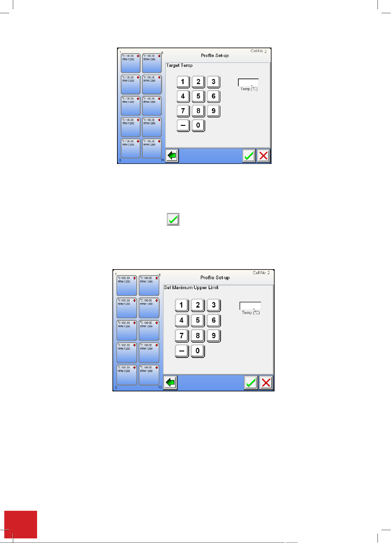
7.11.6. Setting the maximum upper limit
button to accept the value entered.
To help control an exothermic reaction a maximum upper temperature limit may be set. When the Integrity 10
senses an unexpected change in temperature state, action will be taken to prevent the change exceeding the set
maximumtemperaturelimit.Thesetdefaultofthiseldis165.0°C.
Enter the setting using the keypad. Press the button to accept the value entered.
Note: The maximum upper limit may be set to a minus Celsius value.
Toclearthedataeldtouchthe‘redcross’.Ifyounolongerwishtosetamaximumupperlimit,touchtheback
button to return to the previous screen and then touch the ‘red cross’.
Note: To enter -25.6°C Press 2, then 5, then 6, followed by the minus sign.
7.11.7. Setting the plateau time
Thisisthelengthoftimetheuserwishestohavetheunitrunatthetargettemperature.Thedataeldrequires
the user to enter a time in minutes.
Note: Enter the time in minutes. Example, 4 hours 25 minutes is 265 minutes.
44
Page 45
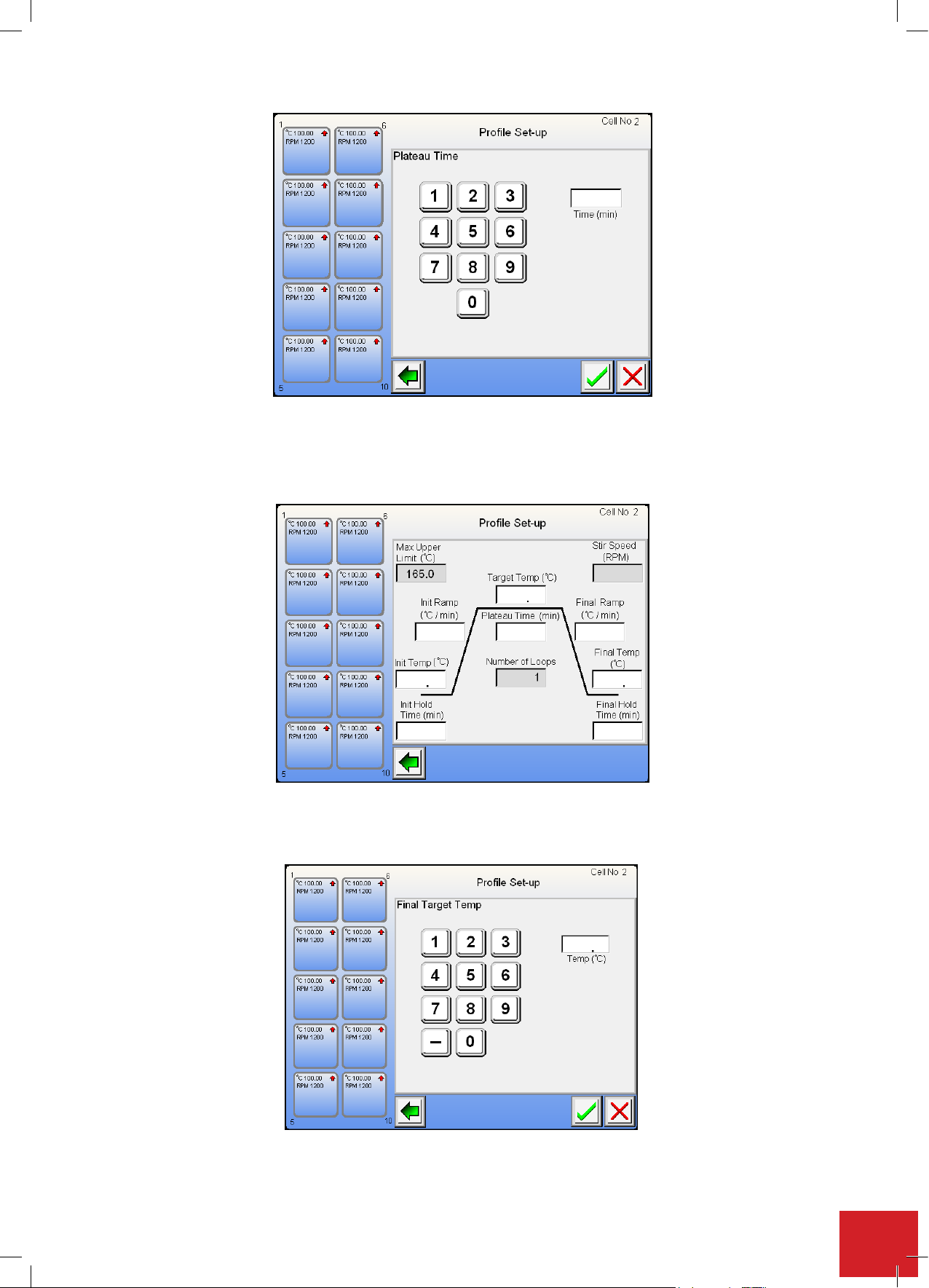
7.11.8. Final temperature
The final temperature is the temperature at which the user wishes the profile to conclude the final step at. Touch
the field to bring up the keypad for entering the required settings.
Usethekeypadtoenterthenaltemperaturevalue.This can be either a positive or negative value.
Note: To enter -25.6 Press 2, then 5, then 6, followed by the minus sign.
45
Page 46
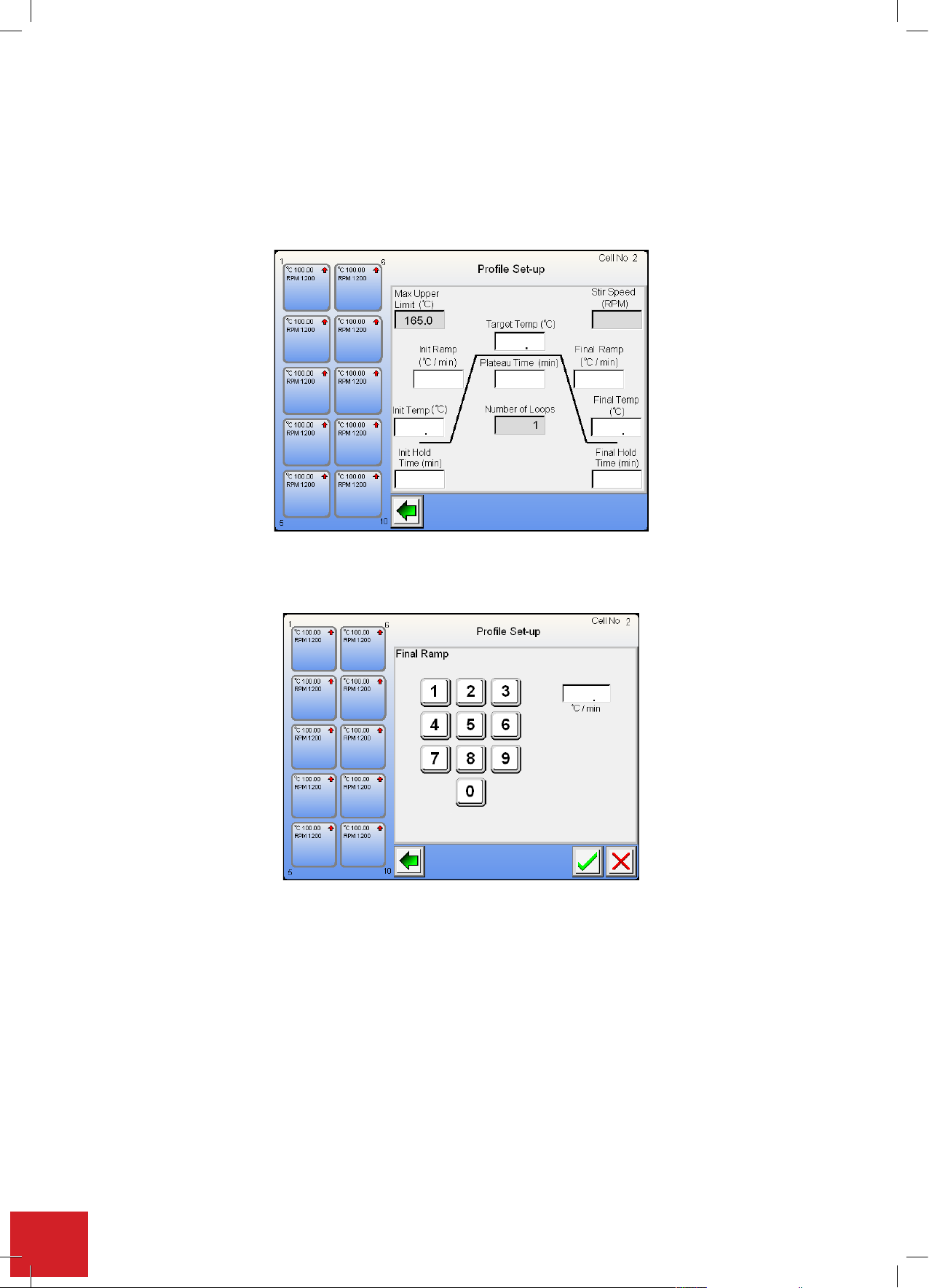
7.11.9. Final ramp
7.11.9. Final ramp: The final ramp is the rate of temperature change from the target temperature to
the final temperature. The final ramp rate can be set to either increase or decrease in
temperature. Touch the field to enter the required setting.
Note: The default setting for ramp rate is 5.0°C per minute. Graduations can be set as
low as 0.1°C per minute. When 0.0 is entered the ramp rate will climb as rapidly as
possible to the set target temperature.
7.11.9. Final ramp: The final ramp is the rate of temperature change from the target temperature to
the final temperature. The final ramp rate can be set to either increase or decrease in
temperature. Touch the field to enter the required setting.
Note: The default setting for ramp rate is 5.0°C per minute. Graduations can be set as
low as 0.1°C per minute. When 0.0 is entered the ramp rate will climb as rapidly as
possible to the set target temperature.
Use the keypad to make the field entry. Touch the green tick button to accept the set value.
Thenalrampistherateoftemperaturechangefromthetargettemperaturetothenaltemperature.Thenal
rampratecanbesettoeitherincreaseordecreaseintemperature.Touchtheeldtoentertherequiredsetting.
Note: The default setting for ramp rate is 5.0°C per minute. Graduations can be set as low as 0.1°C per minute.
When 0.0 is entered the ramp rate will climb as rapidly as possible to the set target temperature.
Usethekeypadtomaketheeldentry.Touchthegreentickbuttontoacceptthesetvalue.
7.11.10. Setting the hold time
Thisisthetimeatwhichtheuserwishestoholdthenaltemperature,afterwhichtheusercanchoosetoeither
stoptherunorrepeattheproleonaloopsetting.
Use the keypad to enter the hold time value in minutes.
Note: Enter the time in minutes. Example, 4 hours 25 minutes is 265 minutes.
46
Page 47
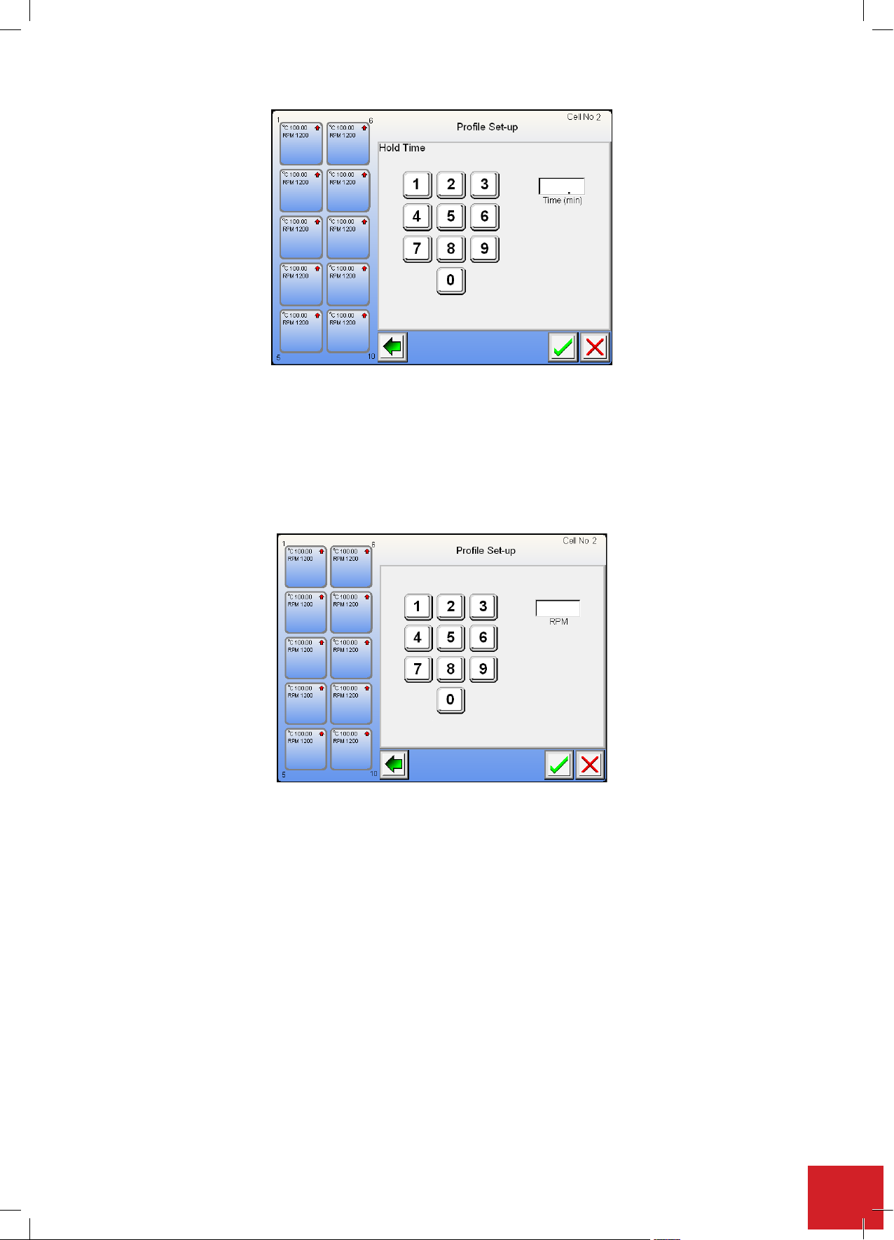
7.11.11. Stir speed
7.11.11
. Stir Speed: The stir speed is set to 0 RPM by default. At this setting the stir facility is
turned off. Turn the stir function on by entering a value. The lowest stir speed that may
be selected is 350RPM. The maximum stir speed value that may be set is 1200RPM.
Touch the field to enter a value.
Use the keypad to enter a stir speed value.
The stir speed is set to 0 RPM by default. At this setting the stir facility is turned off. Turn the stir function on by
entering a value. The lowest stir speed that may be selected is 350RPM. The maximum stir speed value that may
be set is 1200RPM.
Touchtheeldtoenteravalue.
Use the keypad to enter a stir speed value.
7.11.12. Profile loop
By selecting the profile loop the user is given the facility to enter the number of times they wish to loop the
prole.Thedefaultvaluefornumberofloopsissetto1.Tochangethenumberoftimestheproleisrepeated,
touchtheeldboxandusethekeypadtoenterthedesiredvalue.
Note: A maximum of 10 loops may be set per profile (when using the optional integrity PC software this is
increased to 999 times).
Note: The start temperature for all subsequent loops will be the same temperature as the nish temperature of
the preceding loop.
Touch the back arrow to return to the ramp loop selection screen.
47
Page 48
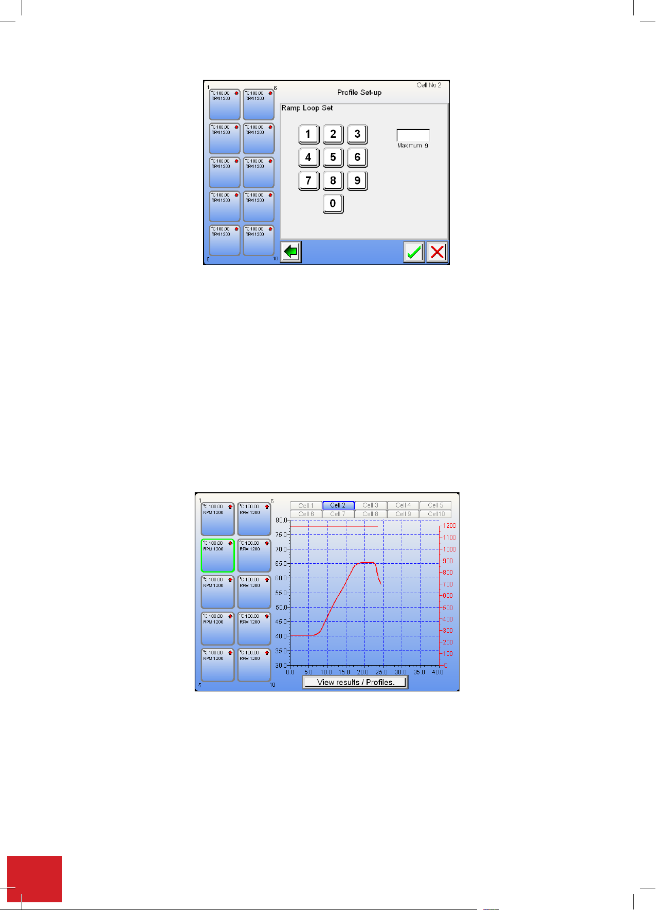
Youarenowpresentedwiththenalsettingscreenfromwhichanychangesmaystillbemadebytouchingthe
You are now presented with the final setting screen from which any changes may still be made by
touching the relevant settings field. The user has the facility to select ‘Save profile’. From here the
user is taken through menu screens which enable to user to store the profile so that it may be used
at a future date. (See ‘Save Profile’). The user may select to copy the profile to the clipboard so that
it can be pasted into other cell profiles. Touch the green tick to return to register the entry and return
to the profile screen.
7.11.13. Copy and Paste a Profile: Once the copy button has been pressed this profile is
copied to the internal clip board and can be pasted into other cells as per 7.10.6.
Touch the Start button to commence running the profile or touch the green tick to accept the profile
settings. Both functions will take the user to the main Home screen. From the home screen touch the
cell you wish to paste the copied profile to.
relevantsettingseld.Theuserhasthefacilitytoselect‘Saveprole’.Fromheretheuseristakenthroughmenu
screenswhichenabletousertostoretheprolesothatitmaybeusedatafuturedate.(See‘SaveProle’).The
usermayselecttocopytheproletotheclipboardsothatitcanbepastedintoothercellproles.Touchthegreen
ticktoreturntoregistertheentryandreturntotheprolescreen.
7.11.13. Copy and paste a profile
Oncethecopybuttonhasbeenpressedthisproleiscopiedtotheinternalclipboardandcanbepastedinto
other cells as per 7.10.6.
TouchtheStartbuttontocommencerunningtheproleortouchthegreenticktoaccepttheprolesettings.
Both functions will take the user to the main Home screen. From the home screen touch the cell you wish to
pastethecopiedproleto.
Touchthe‘Paste’buttontoloadthesavedprolesettingintothiscell.Oncethenewprolehasbeenpopulated
youhavethesameeditingfacilitiesaspertheoriginalprole.Simplytouchtherequiredeldforeditinganduse
the keypad to re-enter data. Touch the green tick to commence cell operation and return to the home screen. If
youdecidetoremovethepastedprole,touchthe‘redcross’.
Note: The saved prole remains on the clipboard. You may select another cell and paste the prole into it.
48
Page 49
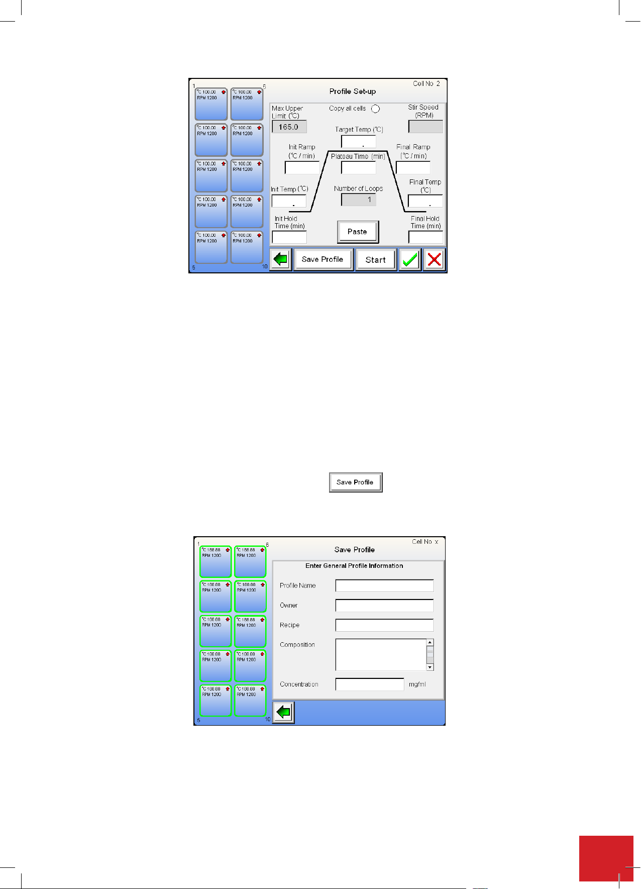
7.11.14. In the event of power loss
TheIntegrity10willturnoff.Alleldsettingswillbelost.Partwrittendatamaybeextractedmanuallyfromthe
SD card using an SD card reader. All previously stored data written to the SD card will be safe.
7.12.
Thepro
composition of the experiment may be added. This profile setting information can be recalled at any time inthe
futureandreloadedintoanygivencellpositioninordertore-runtheprole.Namingandstoringprolesmaybe
undertaken while other cells are in operation.
Note: This feature is only available as an option from the prole setting facility.
Tosavetheprolesettingstouchthe‘SaveProle’button
Youare now taken to the eld selection screen as illustrated below.
Naming and saving a profile
lethathasbeensetinsection7.11.maybenamed.Inaddition,extrainformationaboutthenaturean
d
49
Page 50
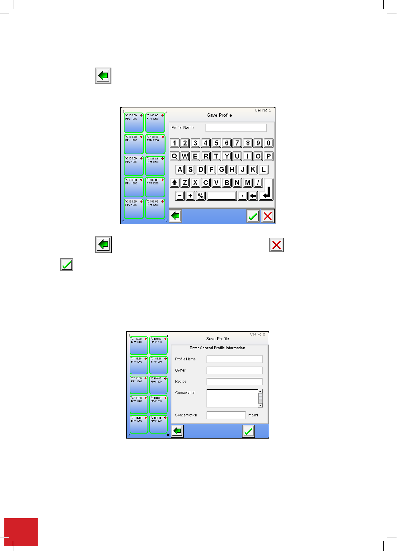
The fields can be completed in any order. All fields must be completed before the profile can be saved.
ill take you back to the previous screen.
button is used to accept the field entry. By touching this button the field entry is accepted.
ouchtherequir redfieldpositiontobetakentotherespectivedatainputscreen.
T
The back button will take you back to the previous screen.
Profile Name:
The back button will take you back to the previous screen. Use this button to remove an incorrect
eldentry.
n w
From the screen below use the keyboard to name the profile.
Thisbuttonisusedtoaccepttheeldentry.Bytouchingthisbuttontheeldentryisaccepted.
YouaretakenbacktotheProleeldselectionscreen.
Usingthesamemethodllinthe‘Owner’,‘Recipe’,‘Composition’and‘Concentration’elds.
Uponcompletionwithinthesaveprolescreenagreentickisnowshown.Touchthetickbuttontoacceptthe
eldentriesandsavetheprole.
Toeditanyoftheeldstouchtherespectiveeldandeditusingthekeyboard.
50
Page 51
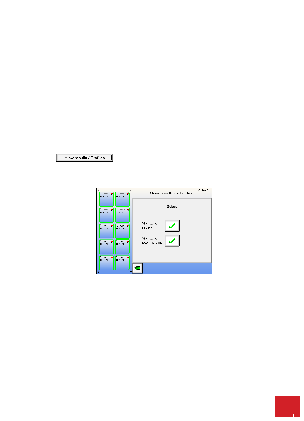
7.13
button.
Stored profile view and copy
Theconceptofstoredproleretrievalistocallupanystoredproleandviewitseldentriesasenteredin
section7.12.Furthermorealloftheprolesettingscanalsobeviewed.Itisalsopossibletoselectandcopy
astoredprolewhichcanthenbepastedtoanyvacantcellposition.Allprolesettingsmaybeeditedandif
requiredtheprolecanberenamedandeditedandstoredasanewprole.
StoredprolescanbeviewedatanytimeregardlessofwhatotherfunctionstheIntegrity10isperforming.Theonly
exception to this is when the screen is locked because of an external control source. See section 7.18.
Note: A prole can’t be stored once the associated experiment run has been completed. It can only be stored
before and during the run of an experiment.
All of this may be undertaken while other cells are in use.
7.13.1. Storing a profile
From the home screen, with or without any cells in use touch the ‘View results /
Proles’ button.
Thenextscreenaskstheuseriftheywishtoviewstoredprolesorviewstoredexperimentdata.Toviewastored
proletouchthetickbuttonassociatedwiththestoredprolestatement.
51
Page 52
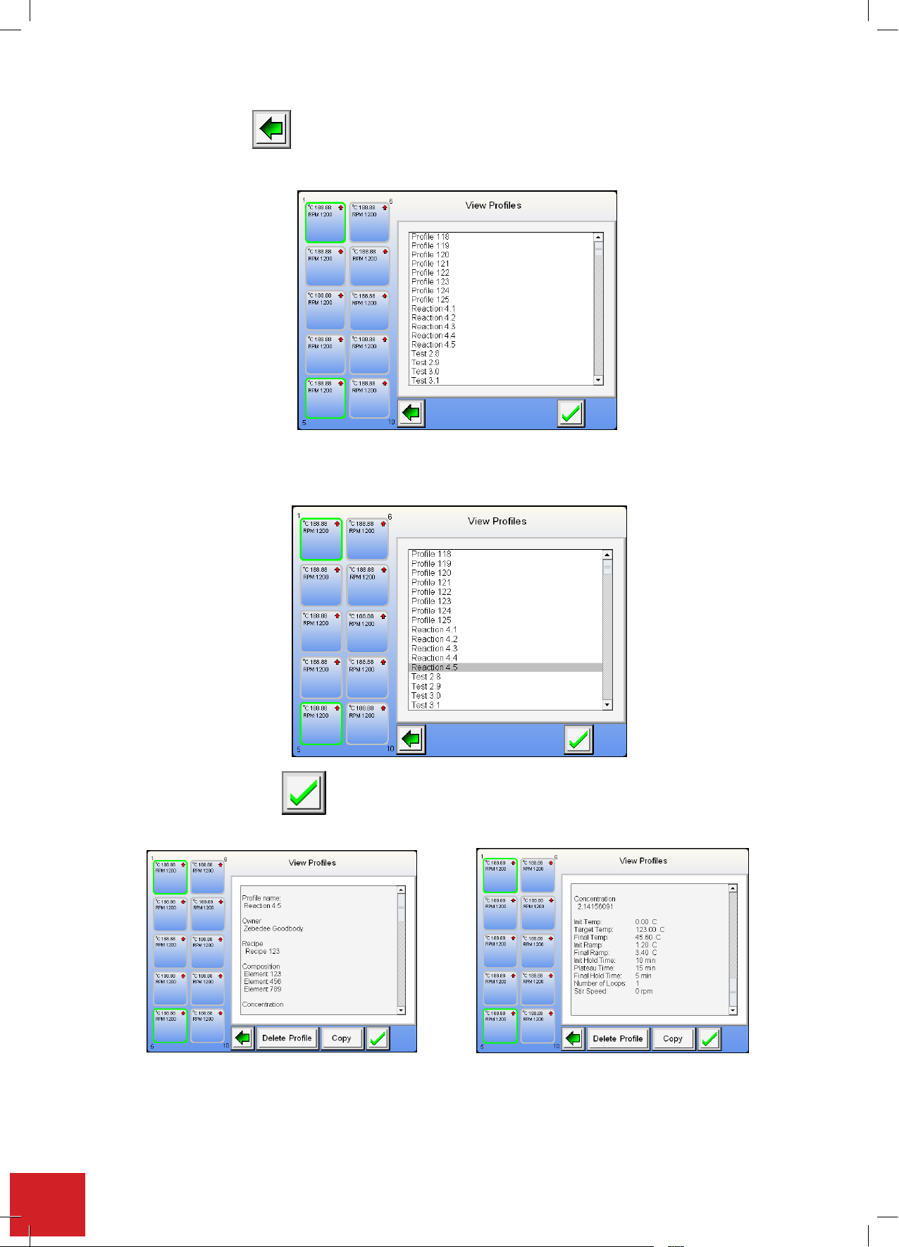
Note: The back button will take you back to the home screen.
Note: T
he back button will take you back to the home screen.
All stored profiles will appear in a list box as shown below. They appear alphabetically and are listed
by profile name.
Note: T
he back button will take you back to the home screen.
All stored profiles will appear in a list box as shown below. They appear alphabetically and are listed
by profile name.
(Example of named profiles)
Touch the profile title to be viewed. It will then become highlighted.
(Example of named profiles)
to accept and view selected profile.
will take you back to the home screen.
Allstoredproleswillappearina listboxasshownbelow.Theyappearalphabeticallyand arelistedbyprole
name.
(Example of named proles)
Touchtheproletitletobeviewed.Itwillthenbecomehighlighted.
Touchthegreentickbutton toacceptandviewselectedprole.
Youarenowabletoviewtheselectedprole.Scrolldownusingthescrollbarstoviewtheprolesettingsaswell
asnamedeldentries.
52
Page 53
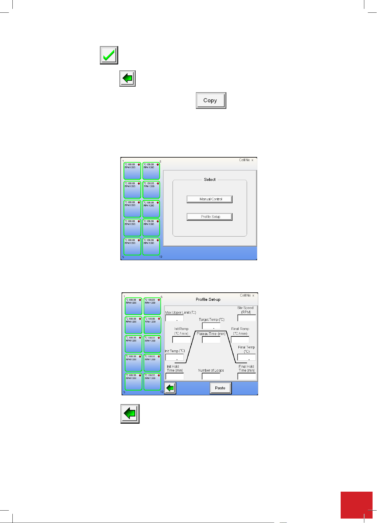
will take you back to the home screen.
. The profile is now copied to
button to return to the profile selection screen.
button to return to the home screen in order to select a different
Touchthegreentick buttontoreturntotheproleselectionscreen.
Touch the green back arrow button to return to the home screen.
Tocopytheproleintoothercellstouchthe‘copy’button .Theproleisnowcopiedtoaninternal
clipboard.
Touchthecellbuttonthatistohavetheprolecopiedto.
Note: Ensure the cell selected is one that is not in operation.
TouchtheProleSetupbuttontobringuptheproleentryeldscreen.
Touchthepastebuttontopopulatealltheeldswiththecopiedprolesettings.
Touch the green back arrow button to return to the home screen in order to select a different cell.
53
Page 54
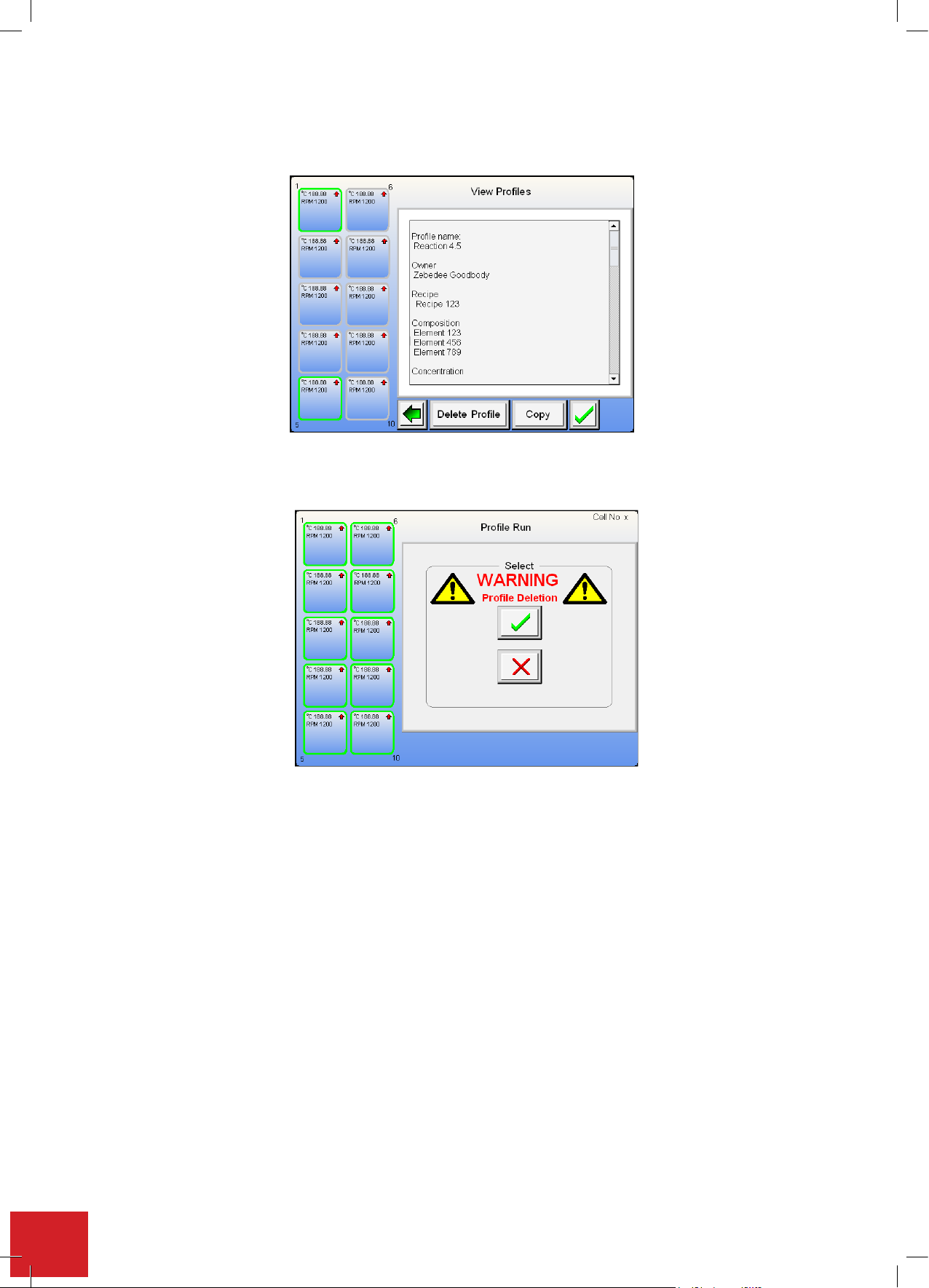
7.13.2. Delete a stored profile
Fromtheproleinformationdisplayscreentouchthe‘DeleteProle’button.
Touchthegreenticktodeletetheprole.Touchthe‘redcross’tocanceltheproledeletion.
54
Page 55
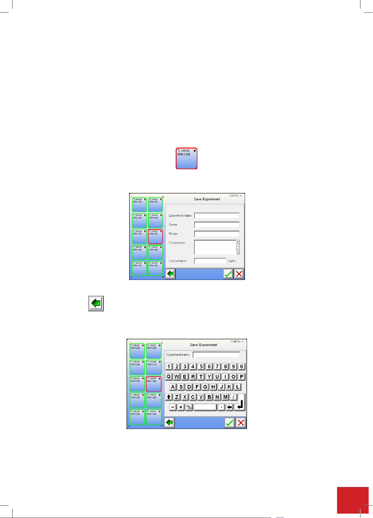
7.14. Saving an experiment
will take you back to the home screen.
Stored experiments are time and date stamped. You should ensure the clock settings are correct (See section 7.7.).
Theprincipledifferencebetweensavingaproleandsavinganexperimentisthataproleissavedwhenithas
beencreated.Aprolecannotbesavedoncetheassociatedexperimentrunhasbeencompleted.
An experiment can
set up or manual control modes.
When an experiment run is complete or the experiment has been stopped a red ring is displayed around to the
cell button. To clear the ring and use the cell again the user must either save the experiment data or decline the
saveexperimentoption.Thisisdonefirstlybytouchingthecell button highlighted with a red ring.
You will now see the screen as illustrated below.
only be saved once it has completed its run. An experiment can be saved from both the profile
Touchtherequiredeldpositiontoinputtherespectiveentry.
The back button will take you back to the home screen.
Note: The elds can be completed in any order.
Experiment name: Use the keyboard to input the experiment name.
55
Page 56
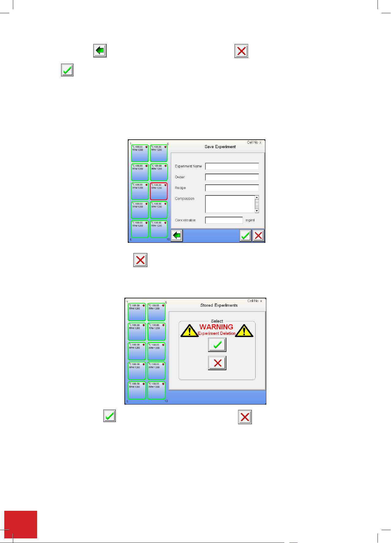
Thebackbuttonwilltakeyoubacktothehomescreen.Usethe button to remove an incorrecteld
button is used to accept the field entry, by touching this button the field entry is accepted
.
button is used to accept the field entry, by touching this button the field entry is accepted
entry.
Thebuttonisusedtoaccepttheeldentry,bytouchingthisbuttontheeldentryisacceptedandtheuser
istakenbacktotheexperimenteldselectionscreen.
CompletetheExperimentOwner,Recipe,CompositionandConcentrationeldsusingthesamemethodasabove.
CLEARING A CELL WITHOUT SAVING DATA: Touch the highlighted cell button.
Now press the Red cross button.
Note: If the elds are lled touching this button will clear out all eld entries.
Ifalltheeldsareblankthenyouaretakentothefollowingcanceloperationscreenasillustrated.
Touchthegreenticktoacceptdatacancellationorthe‘redcross’toreturntotheeldentryscreen.
The red cell ring will change back to grey. The cell is now ready for further use.
56
Page 57
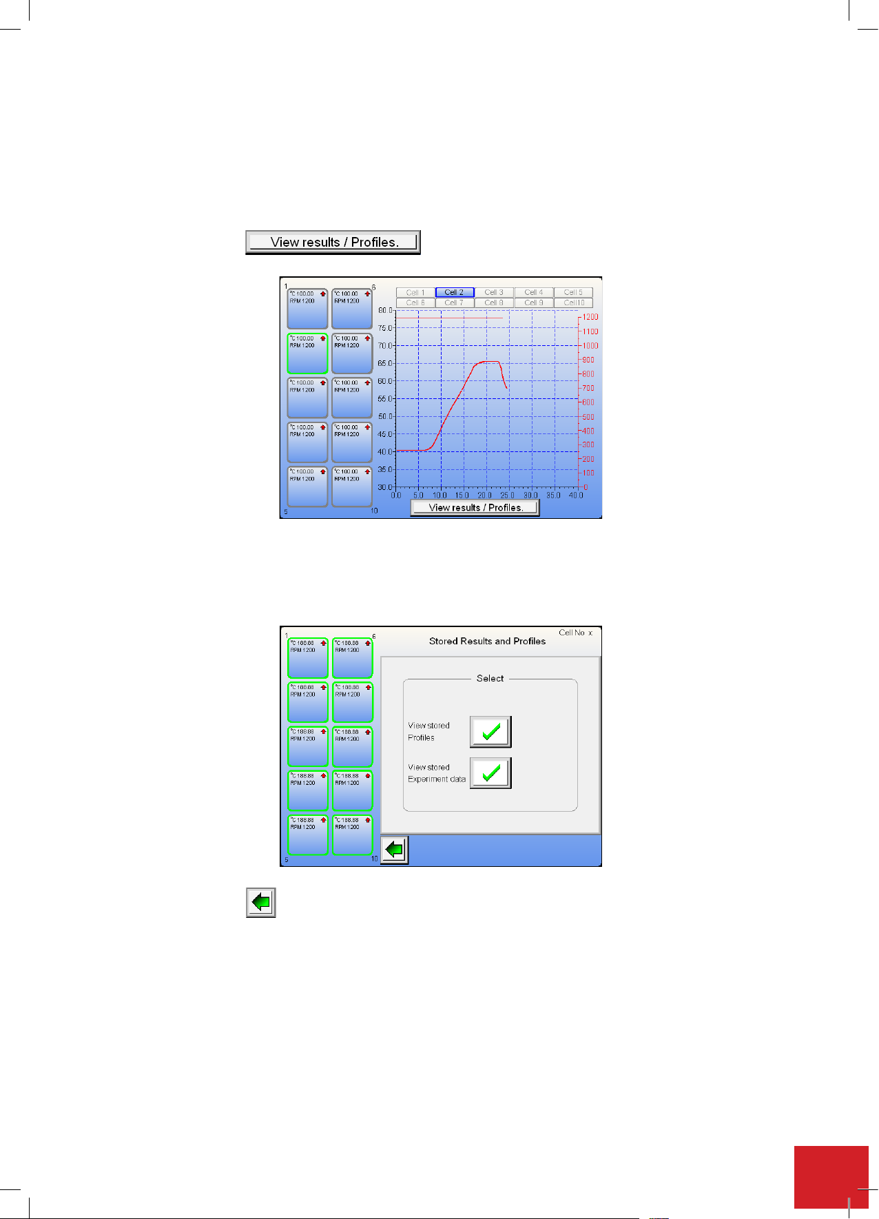
7.15. Reviewing stored experiment data
tton.
Stored experiment data can be viewed at anytime regardless of what other functions the Integrity 10 is performing.
The only exception to this is when the screen is locked because of an external control source. See section 7.18.
7.15.1. Accessing stored experiment data
From the home screen, with or without any cells in use, touch the
‘Viewresults/Proles’
button.
Thenextscreenaskstheuseriftheywishtoviewstoredprolesorviewstoredexperimentdata.ToviewStored
ExperimentDatatouchthetickbuttonassociatedwiththestoredprolestatement.
Note: The back button will take you back to the home screen.
57
Page 58
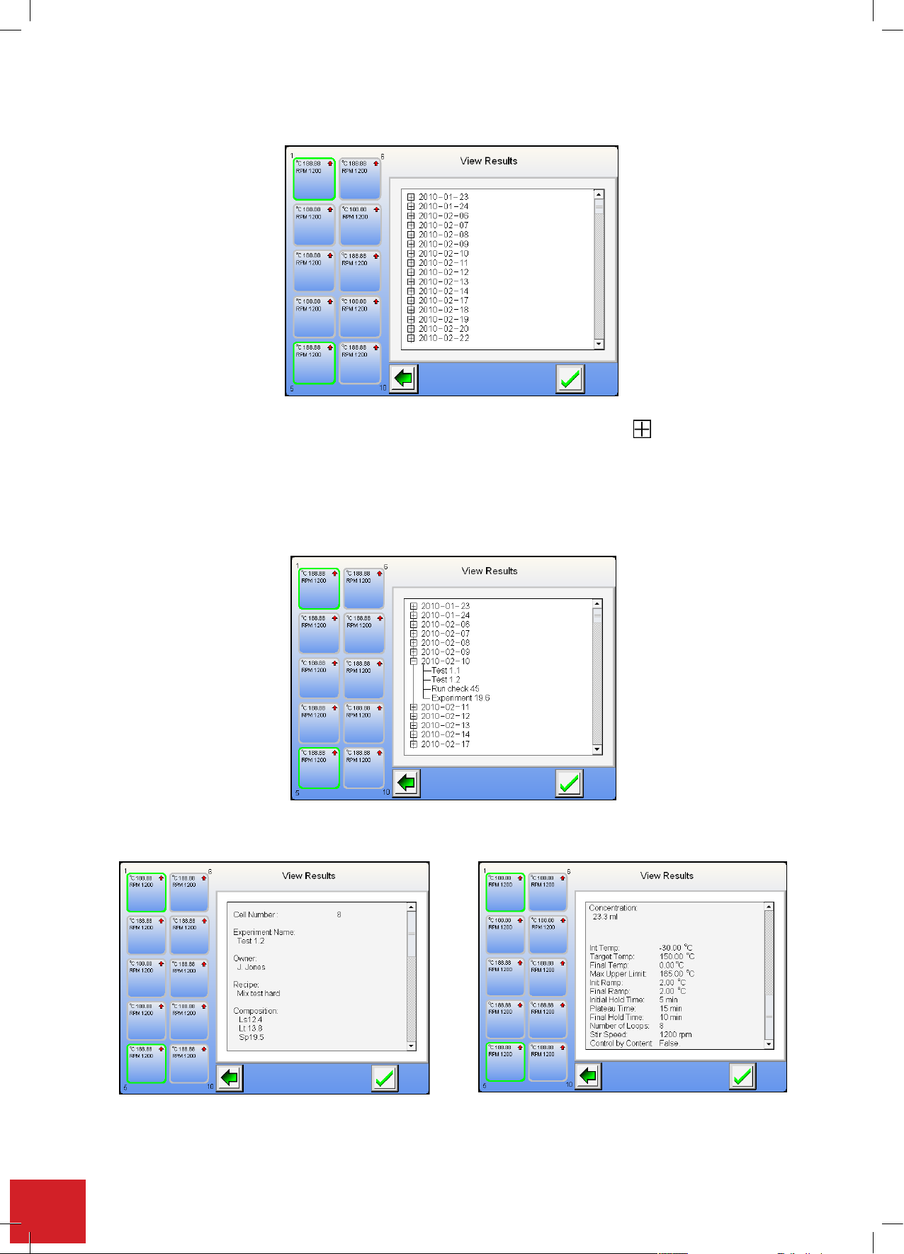
You are now taken to the screen as illustrated below.
You are now taken to the screen as illustrated below.
Ea
ch date in the cascade tree can be expanded by touching on the expansion button.
From here you can view all the stored experiments for that date. Touch the expansion again to close
the cascade.
Select the experiment to be viewed by touching on it to highlight it. Confirm the selection by touching
the green tick.
Use the scroll bars to view all settings and title information associated with the experiment.
Each date in the cascade tree can be expanded by touching on the expansion button.
From here you can view all the stored experiments for that date. Touch the expansion again to close the cascade.
Selecttheexperimenttobeviewedbytouchingonittohighlightit.Conrmtheselectionbytouchingthegreen
tick.
Use the scroll bars to view all settings and title information associated with the experiment.
Touch the green tick button to view the raw recorded data.
58
Page 59
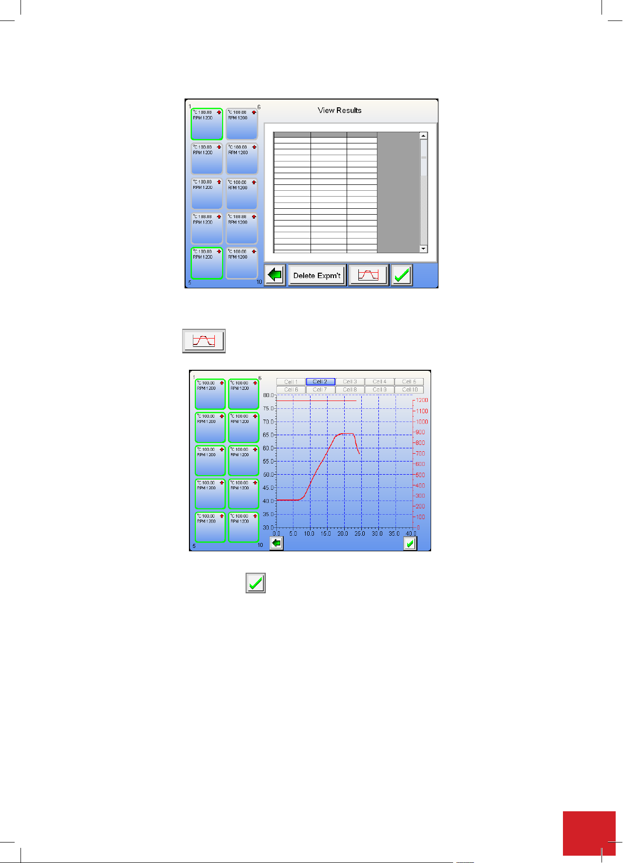
The screen will look like the illustration below.
to view the data
button is used to accept the field entry, by touching this button the field entry is accepted
7.15.2. Viewing data in graphical format
Touch the Graph button to view the data presented in a graphical format.
To return to raw data format, touch the green tick button.
59
Page 60
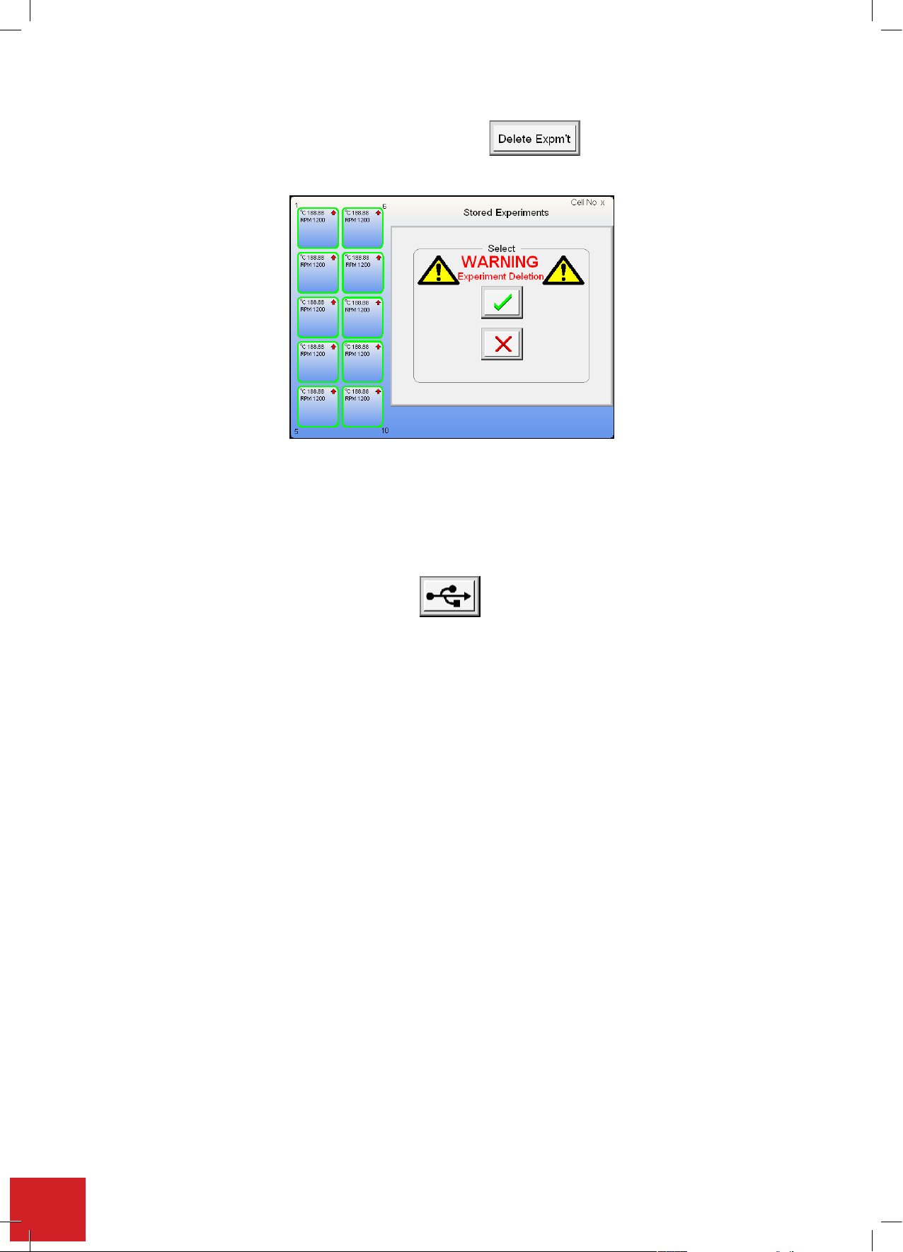
7.15.3. Deleting experimental data
data in graphical format: Touch the Graph button to view the data
presented in a graphical format.
. You are now asked to confirm experiment deletion. Touch the green tick to
From the raw data screen touch the Delete Experiment button . Youarenowaskedtoconrm
experiment deletion. Touch the green tick to accept or the red cross and return to the raw data screen.
7.16. Outputting stored data via USB flash drive
Select the view experiment set-up or the Raw Data Screen (see section 7.15). Insert a USB Flash Drive into the
master USB socket found on the front of the Integrity unit (see 7.1). After 10 seconds or less the USB download
button will appear on the screen.
Touch the button and the raw data and a ‘read me’ le containing the experiment parameter settings will
automatically download.
Once the download is complete a download statement will appear conrming its completion. Touch the OK
button.ItisnowsafetoremovetheUSBashdrive.
erawdatam
Th aybeviewedbyopeninginMicrosoftExcel.ThereadmefileisaMicrosoftnotepadfile.
60
Page 61
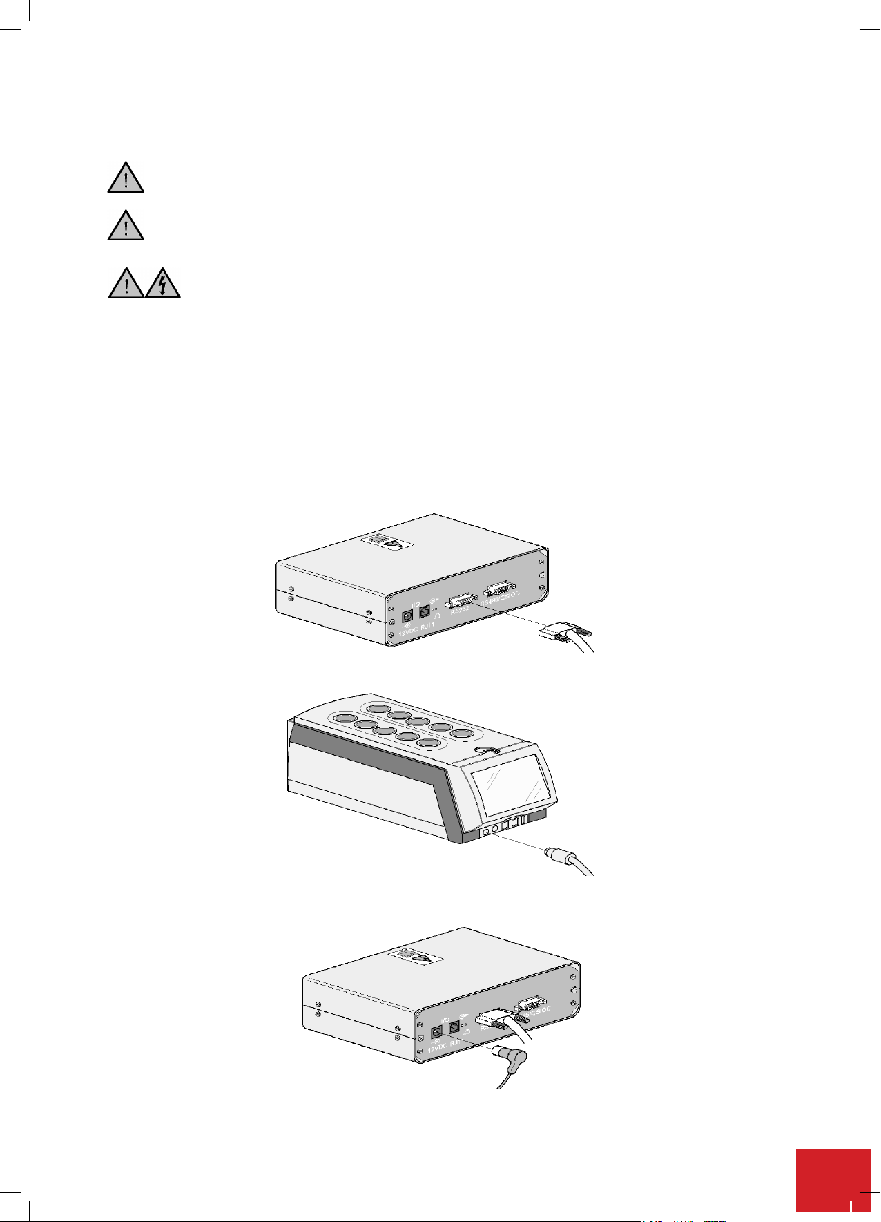
7.17. Control by contents
module – ATS10001 Optional)
Ensure the Integrity 10 is turned off before commencing the installation of Multitemp
module – ATS10001 Optional)
Ensure the Integrity 10 is turned off before commencing the installation of Multitemp
module – ATS10001 Optional)
Ensure the Integrity 10 is turned off before commencing the installation of Multitemp
Use the Multitemp in conjunction with the Electrothermal operating instruction book supplied
with thi uct.
ATTENTION.
Do not install the Multitemp on a surface which may become wet as the
Do not install the Multitemp on a surface which may become wet as the
s temperature. Thermocouples placed in the chemical solutions are
ATS10001 Option accessory) and
Do not install the Multitemp on a surface which may become wet as the
s temperature. Thermocouples placed in the chemical solutions are
ATS10001 Option accessory) and
Do not install the Multitemp on a surface which may become wet as the
ATS10001 Option accessory) and
(Using the optional Electrothermal ATS10001 Multi-Temp module)
Ensure the Integrity 10 is turned off before commencing the installation of Multi-Temp
Use the Multi-Temp in conjunction with the Electrothermal operating instruction book (M7559) supplied
with this product.
ATTENTION Do not install the Multi-Temp on a surface which may become wet as the result of
using chilled water.
The Multi-Temp is used when accurate control of the sample temperature is imperative. The Multi-Temp is used to
control the contents temperature. Thermocouples placed in the chemical solutions are connected to the
Multi-Temp which feeds back constant information on the exact sample temperature. The Integrity 10 measures
the temperature from the thermocouples via the Multi-Temp then adjusts and monitors the sample temperature
according to the temperature settings under both manual and profile control.
7.17.1. Installation of the Multi-Temp
Take the Multi-Temp unit (ATS10001 optional accessory) and connect it to the Integrity 10 unit. Plug the 'D' type
connector into the RS232 socket found on the back of the Multi-Temp case.
Connect the other end of the lead to the RS232, 10 pin output of the Integrity 10 unit.
RS232
Using the power supply supplied with the Multi-Temp, plug in the jack plug to the 12 Volts DC in socket on the rear
panel of the Multi-Temp. Connect the other end to a suitably rated A.C. mains power source.
Fill the required glassware with solution and place it in the required cells. (If required use in conjunction with other
Electrothermalaccessories,e.g.thereuxunit,ATS20100).
12VDC
61
Page 62
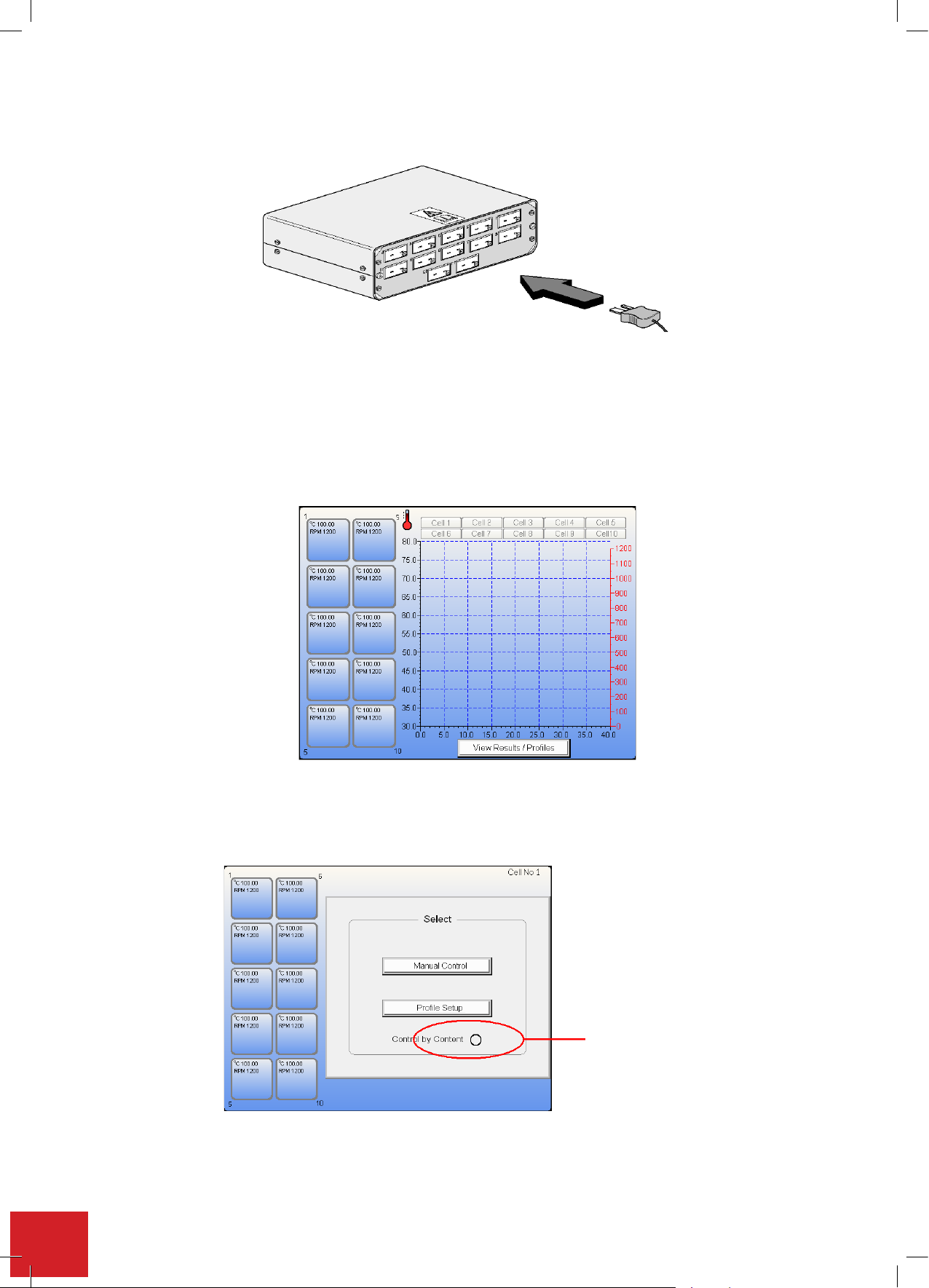
button to select the cell for operation.
Plug the thermocouples into the respective Multi-Temp front panel position that corresponds to the Integrity 10
cells to be used. Example use thermocouple plug position 1 for Integrity 10 cell position 1, thermocouple position
2 for Integrity 10 cell position 2 and so on.
Place the probe tip ends of the thermocouples into the appropriate cell glassware ensuring the end of the
thermocouple is placed well inside the solution.
7.17.2. Operating the Multi-Temp
Turn on the Integrity 10 unit and operate as previously described. Again the home screen will be seen after the
warm up.
Note: the thermometer symbol indicating connection.
Press the cell button to select the cell for operation.
IntheManualorProlecontrolselectionscreen,touchthecheckboxtoconrmtheuseof‘controlbycontent’
using
the Multi-Temp.
the check box only appears when a Multi-Temp is connected.
Note:
Select‘ManualControl’or‘ProleSetup’andinputthesettingasdescribedpreviously.
Check Control
by Contents
62
Page 63
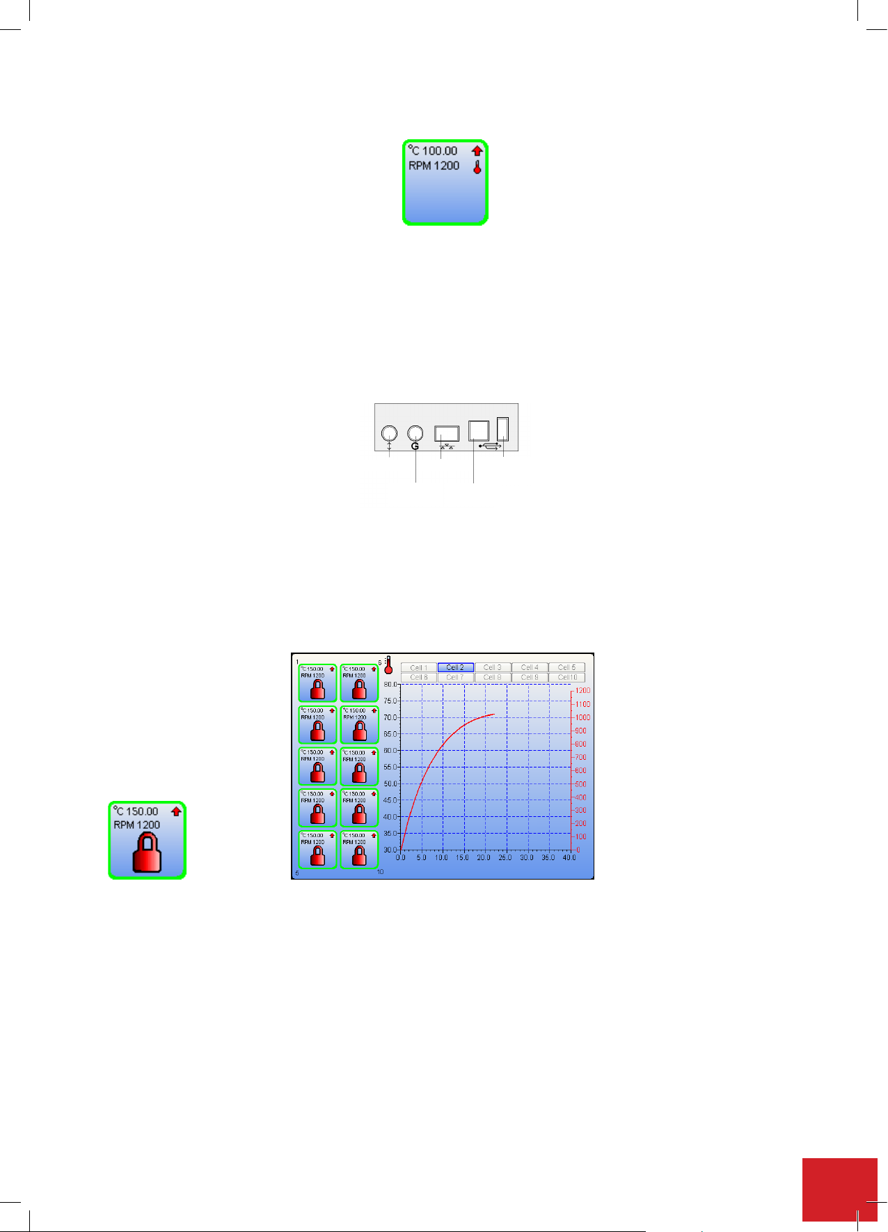
Observe: The cell button of a ‘Control by Contents’ cell will also display the ‘Multi-Temp present’
suited for the controlling application.
Thermometer Icon.
NOTE: The temperature value displayed in the cell button and shown on the graph is the measured
temperature of the contents, NOT the block temperature.
7.18. External control – optional
7.18.1. PC control:
Connect the host PC to the Integrity 10 unit using the appropriate input socket as suited for the controlling
application.
Open the Integrity software application (ATS11005 on the host PC (see M8162 instruction manual for Integrity
software).
With all the services connected to the Integrity, turn on and wait for the home screen to appear.
A lock icon will appea
able to control the Integrity 10 unit through the host PC and Integrity 10 software.
RS232/485
Ethernet
GSIOC
Protocol
USB
Master
USB
Slave
r on all the cell positions and you will not be able to use the touchscreen. You will only be
Note: You can’t operate cells under external control using the Integrity 10 touch screen.
Upon completion of a run, turn off the Integrity 10 using the Power Supply I/O button as detailed in section 7.5.
63
Page 64

8. Chemical resistance
Resistance Resistance
It is recommended that any chemical spillages are cleaned up immediately.
Side Panels / Front pod Drip plate
FRPS/ABS Polypropylene
Chemical 20°C 60°C 20°C 60°C
Acetaldehyde Major Effect Major Effect No data No data
Acetic acid (10%) Excellent
Resistance
Acetic acid
(glac./anh)
Acetic anhydride Major Effect Major Effect No data No data
Aceto-acetic ester Major Effect Major Effect No data No data
Acetone Major Effect Major Effect Major Effect Major Effect
Other Ketones Major Effect Major Effect No data No data
Acetonitrile No data No data No data No data
Acetylene No data No data No data No data
Acetyl salicylic Acid Major Effect Major Effect No data No data
Acid fumes Major Effect Major Effect No data No data
Acid salt No data No data Excellent
Alchols Major Effect Major Effect No data No data
Aliphatic esters Major Effect Major Effect No data No data
Alkyl chlorides Major Effect Major Effect No data No data
Alum Excellent
Aluminium chloride
Aluminium sulphate
Ammonia anhydrous
Ammonia, aqueous
Ammonium chloride
Amyl acetate Major Effect Major Effect No data No data
Aniline Major Effect Major Effect
Antimony tricloride
Aqua ammonia No data No data
Aqua regia Major Effect Major Effect No data No data
Aromatic solvents Major Effect Major Effect No data No data
Ascorbic acid Major Effect Major Effect No data No data
Basic salt
Beer
Benzaldehyde
Benzene Major Effect Major Effect No data No data
Benzoic acid
Benzoyl peroxide
Boric acid
Brines, saturated Excellent Excellent No data No data
Major Effect Major Effect Excellent
Resistance
Excellent
Resistance
Excellent
Resistance
Excellent
Resistance Major Effect No data No data
Excellent
Resistance Major Effect No data No data
Excellent
Resistance
Excellent
Resistance
Excellent
Resistance
Excellent
Resistance
Excellent
Resistance No data No data No data
Excellent
Resistance
Excellent
Resistance No data No data No data
Excellent
Resistance
Major Effect Excellent
Resistance
Resistance
Resistance
Excellent
Resistance
Excellent
Resistance No data No data
Excellent
Resistance No data No data
Excellent
Resistance No data No data
Excellent
Resistance No data No data
Excellent
Resistance
Excellent
Resistance No data No data
Excellent
Resistance
Excellent
Resistance
No data No data
Excellent
Resistance Excellent Resistance
Excellent
Resistance Excellent Resistance
Excellent
Resistance Excellent Resistance
Excellent
Resistance Excellent Resistance
Excellent
Resistance Excellent Resistance
Excellent Resistance
Excellent Resistance
Excellent Resistance
64
Page 65

Resistance Resistance
Excellent
Excellent
Side Panels / Front pod Drip plate
FRPS/ABS Polypropylene
Chemical 20°C 60°C 20°C 60°C
Bromine (K) solution
Bromine Major Effect Major Effect No data No data
Bromine liquid, tech Major Effect Major Effect No data No data
Bromine water,
saturated aqueous Major Effect Major Effect No data No data
Butyl acetate No data No data
Calcium chloride
calcium hydroxide No data No data No data No data
Carbon dioxide
Carbon monoxide
Carbon disulphide Major Effect Major Effect Major Effect Major Effect
Carbonic acid
carbonic tetrachloride Major Effect Major Effect Major Effect Major Effect
Caustic soda &
potash
Cellulose paint No data No data No data No data
Chlorhydric acid
(10%) No data No data
Chlorhydric acid
(37%) No data No data
Chlorates of Na, K,
Ba
Chlorine, dry
Chlorine, wet
Chloroacetic acid Major Effect Major Effect No data No data
Chlorobenzene Major Effect Major Effect Major Effect Major Effect
Chloroform Major Effect Major Effect No data No data
Chlorosulphic acid Major Effect Major Effect No data No data
Chromic acid (80%)
Citric acid
Copper salts (most)
Cresylic acids (50%) Major Effect Major Effect No data No data
Cyclohexane Major Effect Major Effect No data No data
Detergents, synthetic
Esters Major Effect Major Effect No data No data
Ether Major Effect Major Effect No data No data
Fatty acids (>C6)
Ferric chloride
Ferrous sulphate
Fluorinated
refrigerants Major Effect Major Effect No data No data
Fluorine, dry Major Effect Major Effect No data No data
Fluorine, wet Major Effect Major Effect No data No data
Fluorosilicate acid Major Effect Major Effect No data No data
Resistance
Excellent
Resistance
Excellent
Resistance
Excellent
Resistance
Excellent
Resistance
Excellent
Resistance
Excellent
Resistance
Excellent
Resistance
Excellent
Resistance
Excellent
Resistance Major Effect
Excellent
Resistance
Excellent
Resistance
Excellent
Resistance Major Effect No data No data
Excellent
Resistance
Excellent
Resistance
Excellent
Resistance
Resistance No data No data
Excellent
Resistance Excellent Resistance
Excellent
Resistance
Excellent
Resistance
Excellent
Resistance
Excellent
Resistance No data No data
Excellent
Resistance
Excellent
Resistance No data No data
Excellent
Resistance
Excellent
Resistance
Excellent
Resistance
Excellent
Resistance No data No data
Excellent
Resistance No data No data
Excellent
Resistance No data No data
Excellent
Resistance No data No data
Excellent
Resistance Excellent Resistance
Excellent
Resistance Excellent Resistance
Excellent
Resistance Excellent Resistance
Excellent
Resistance Excellent Resistance
Excellent
Resistance Excellent Resistance
Excellent
Resistance Major Effect
Excellent
Resistance Major Effect
Excellent
Resistance Major Effect
Excellent
Resistance Excellent Resistance
Excellent
Resistance Excellent Resistance
65
Page 66

Resistance Resistance
Bromine (K) solution
Excellent
Resistance
Excellent
Resistance No data No data
Bromine Major Effect Major Effect No data No data
Bromine liquid, tech Major Effect Major Effect No data No data
Bromine water,
saturated aqueous Major Effect Major Effect No data No data
Butyl acetate No data No data
Excellent
Resistance Excellent Resistance
Calcium chloride
Excellent
Resistance
Excellent
Resistance
Excellent
Resistance Excellent Resistance
calcium hydroxide No data No data No data No data
Carbon dioxide
Excellent
Resistance
Excellent
Resistance
Excellent
Resistance Excellent Resistance
Carbon monoxide
Excellent
Resistance
Excellent
Resistance
Excellent
Resistance Excellent Resistance
Carbon disulphide Major Effect Major Effect Major Effect Major Effect
Carbonic acid
Excellent
Resistance
Excellent
Resistance No data No data
carbonic tetrachloride Major Effect Major Effect Major Effect Major Effect
Caustic soda &
potash
Excellent
Resistance
Excellent
Resistance
Excellent
Resistance Excellent Resistance
Cellulose paint No data No data No data No data
Chlorhydric acid
(10%) No data No data
Excellent
Resistance Excellent Resistance
Chlorhydric acid
(37%) No data No data
Excellent
Resistance Major Effect
Chlorates of Na, K, BaExcellent
Resistance
Excellent
Resistance No data No data
Chlorine, dry
Excellent
Resistance
Excellent
Resistance
Excellent
Resistance Major Effect
Chlorine, wet
Excellent
Resistance
Excellent
Resistance
Excellent
Resistance Major Effect
Chloroacetic acid Major Effect Major Effect No data No data
Chlorobenzene Major Effect Major Effect Major Effect Major Effect
Chloroform Major Effect Major Effect No data No data
Chlorosulphic acid Major Effect Major Effect No data No data
Chromic acid (80%)
Excellent
Resistance Major Effect
Excellent
Resistance Excellent Resistance
Citric acid
Excellent
Resistance
Excellent
Resistance
Excellent
Resistance Excellent Resistance
Copper salts (most)
Excellent
Resistance
Excellent
Resistance No data No data
Cresylic acids (50%) Major Effect Major Effect No data No data
Cyclohexane Major Effect Major Effect No data No data
Detergents, synthetic
Excellent
Resistance Major Effect No data No data
Esters Major Effect Major Effect No data No data
Ether Major Effect Major Effect No data No data
Fatty acids (>C6)
Excellent
Resistance
Excellent
Resistance No data No data
Ferric chloride
Excellent
Resistance
Excellent
Resistance No data No data
Ferrous sulphate
Excellent
Resistance
Excellent
Resistance No data No data
Fluorinated
refrigerants Major Effect Major Effect No data No data
Fluorine, dry Major Effect Major Effect No data No data
Fluorine, wet Major Effect Major Effect No data No data
Fluorosilicate acid Major Effect Major Effect No data No data
Formaldehyde (40%) Excellent Excellent No data No data
Side Panels / Front pod Drip plate
Resistance Resistance
FRPS/ABS Polypropylene
Chemical 20°C 60°C 20°C 60°C
Excellent
Formic acid
Fruit juice
66
Gelatin
Glycerin
Glycol, ethylene
Glycols Major Effect Major Effect No data No data
Glycolic acid Major Effect Major Effect No data No data
Hexamethylene
diamine No data No data No data No data
Hexamine Major Effect Major Effect No data No data
Hydrazine No data No data No data No data
Hydrobromic acid
(50%)
Hydrochloric acid
(10%)
Hydrochloric acid
(conc)
Hydrocyanic acid
Hydrofluoric acid
(40%)
Hydrofluoric acid
(75%) Major Effect Major Effect No data No data
Hydrogen peroxide
(30-90%)
Hydrogen sulphide No data No data
Hypochlorite’s (Ma
12-14%)
Iso-butyl-acetate No data No data No data No data
Lactic acid (90%)
Lead acetate
Lead perchlorate No data No data No data No data
Lime (CaO)
Maleic acid
Manganate,
potassium (K)
Meat Juice
Mercuric chloride
Mercury
Methanol Major Effect Major Effect No data No data
Methylene chloride Major Effect Major Effect Major Effect Major Effect
Milk products
Moist air
Resistance
Excellent
Resistance
Excellent
Resistance
Excellent
Resistance
Excellent
Resistance
Excellent
Resistance Major Effect
Excellent
Resistance
Excellent
Resistance Major Effect No data No data
Excellent
Resistance
Excellent
Resistance Major Effect No data No data
Excellent
Resistance Major Effect No data No data
Excellent
Resistance Major Effect No data No data
Excellent
Resistance
Excellent
Resistance
Excellent
Resistance
Excellent
Resistance
Excellent
Resistance
Excellent
Resistance
Excellent
Resistance Major Effect No data No data
Excellent
Resistance
Excellent
Resistance Major Effect No data No data
Excellent
Resistance
Excellent
Resistance No data No data
Excellent
Resistance No data No data
Excellent
Resistance No data No data
Excellent
Resistance No data No data
Excellent
Resistance No data No data
Excellent
Resistance No data No data
Excellent
Resistance
Excellent
Resistance No data No data
Excellent
Resistance No data No data
Excellent
Resistance No data No data
Excellent
Resistance
Excellent
Resistance No data No data
Excellent
Resistance No data No data
Excellent
Resistance No data No data
Excellent
Resistance No data No data
Excellent
Resistance Major Effect
Excellent
Resistance Excellent Resistance
Excellent
Resistance Excellent Resistance
Excellent
Resistance Excellent Resistance
Page 67

Picric acid No data No data No data No data
Side Panels / Front pod Drip plate
Resistance Resistance
Formic acid
Excellent
Resistance
Excellent
Resistance No data No data
Fruit juice
Excellent
Resistance
Excellent
Resistance No data No data
Gelatin
Excellent
Resistance
Excellent
Resistance No data No data
Glycerin
Excellent
Resistance
Excellent
Resistance No data No data
Glycol, ethylene
Excellent
Resistance
Excellent
Resistance No data No data
Glycols Major Effect Major Effect No data No data
Glycolic acid Major Effect Major Effect No data No data
Hexamethylene
diamine No data No data No data No data
Hexamine Major Effect Major Effect No data No data
Hydrazine No data No data No data No data
Hydrobromic acid
(50%)
Excellent
Resistance Major Effect
Excellent
Resistance Major Effect
Hydrochloric acid
(10%)
Excellent
Resistance
Excellent
Resistance No data No data
Hydrochloric acid
(conc)
Excellent
Resistance Major Effect No data No data
Hydrocyanic acid
Excellent
Resistance
Excellent
Resistance
Excellent
Resistance Excellent Resistance
Hydrofluoric acid
(40%)
Excellent
Resistance Major Effect No data No data
Hydrofluoric acid
(75%) Major Effect Major Effect No data No data
Hydrogen peroxide
(30-90%)
Excellent
Resistance Major Effect No data No data
Hydrogen sulphide No data No data
Excellent
Resistance Excellent Resistance
Hypochlorite’s (Ma
12-14%)
Excellent
Resistance Major Effect No data No data
Iso-butyl-acetate No data No data No data No data
Lactic acid (90%)
Excellent
Resistance
Excellent
Resistance No data No data
Lead acetate
Excellent
Resistance
Excellent
Resistance No data No data
Lead perchlorate No data No data No data No data
Lime (CaO)
Excellent
Resistance
Excellent
Resistance No data No data
Maleic acid
Excellent
Resistance
Excellent
Resistance
Excellent
Resistance Excellent Resistance
Manganate,
potassium (K)
Excellent
Resistance
Excellent
Resistance No data No data
Meat Juice
Excellent
Resistance
Excellent
Resistance No data No data
Mercuric chloride
Excellent
Resistance Major Effect No data No data
Mercury
Excellent
Resistance
Excellent
Resistance No data No data
Methanol Major Effect Major Effect No data No data
Methylene chloride Major Effect Major Effect Major Effect Major Effect
Milk products
Excellent
Resistance Major Effect No data No data
Moist air
Excellent
Resistance
Excellent
Resistance No data No data
FRPS/ABS Polypropylene
Chemical 20°C 60°C 20°C 60°C
Excellent
Molasses
Monoethanolamine Major Effect Major Effect No data No data
Naphtha
Naphthalene Major Effect Major Effect No data No data
Neutral salt
Nickel salts
Nitrates of Na, K and
NH3
Nitric acid (<25%) Major Effect Major Effect
Nitric acid (<50%) Major Effect Major Effect Major Effect Major Effect
Nitric acid (<90%) Major Effect Major Effect Major Effect Major Effect
Nitric acid (fuming) Major Effect Major Effect Major Effect Major Effect
Nitrite (Na)
Nitrobenzene Major Effect Major Effect Major Effect Major Effect
Oils, diesel No data No data No data No data
Oils, essential
Oils, lubricating +
aromatic additives Major Effect Major Effect No data No data
Oils, mineral
Oils, vegetable and
animal
Oleic acid No data No data
Oxalic acid
Ozone Major Effect Major Effect No data No data
Paraffin wax
Perchloric acid No data No data
Petroleum sprit Major Effect Major Effect Major Effect Major Effect
Phenol Major Effect Major Effect
Phosphoric acid
(20%)
Phosphoric acid
(50%)
Phosphoric acid
(95%)
Phosphorous
chloride No data No data No data No data
Phosphorous
pentoxide No data No data No data No data
Phthalic acid No data No data
Potassium
bicarbonate No data No data
Potassium
permanganate No data No data
Potassium hydroxide No data No data
Resistance Major Effect No data No data
Excellent
Resistance Major Effect No data No data
Excellent
Resistance
Excellent
Resistance
Excellent
Resistance
Excellent
Resistance Major Effect No data No data
Excellent
Resistance
Excellent
Resistance
Excellent
Resistance
Excellent
Resistance Major Effect
Excellent
Resistance
Excellent
Resistance Major Effect
Excellent
Resistance Major Effect
Excellent
Resistance Major Effect
Excellent
Resistance
Excellent
Resistance No data No data
Excellent
Resistance No data No data
Excellent
Resistance No data No data
Excellent
Resistance No data No data
Excellent
Resistance No data No data
Excellent
Resistance No data No data
Excellent
Resistance Excellent Resistance
Excellent
Resistance Major Effect
Excellent
Resistance Major Effect
Excellent
Resistance Excellent Resistance
Excellent
Resistance Excellent Resistance
Excellent
Resistance Excellent Resistance
Excellent
Resistance Excellent Resistance
Excellent
Resistance Excellent Resistance
Excellent
Resistance Excellent Resistance
Excellent
Resistance Excellent Resistance
Excellent
Resistance Excellent Resistance
Excellent
Resistance Excellent Resistance
Excellent
Resistance Excellent Resistance
67
Page 68

Side Panels / Front pod Drip plate
Monoethanolamine Major Effect Major Effect No data No data
Naphtha
Excellent
Resistance Major Effect No data No data
Naphthalene Major Effect Major Effect No data No data
Neutral salt
Excellent
Resistance
Excellent
Resistance
Excellent
Resistance Excellent Resistance
Nickel salts
Excellent
Resistance
Excellent
Resistance No data No data
Nitrates of Na, K and
NH3
Excellent
Resistance
Excellent
Resistance No data No data
Nitric acid (<25%) Major Effect Major Effect
Excellent
Resistance Major Effect
Nitric acid (<50%) Major Effect Major Effect Major Effect Major Effect
Nitric acid (<90%) Major Effect Major Effect Major Effect Major Effect
Nitric acid (fuming) Major Effect Major Effect Major Effect Major Effect
Nitrite (Na)
Excellent
Resistance Major Effect No data No data
Nitrobenzene Major Effect Major Effect Major Effect Major Effect
Oils, diesel No data No data No data No data
Oils, essential
Excellent
Resistance
Excellent
Resistance No data No data
Oils, lubricating +
aromatic additives Major Effect Major Effect No data No data
Oils, mineral
Excellent
Resistance
Excellent
Resistance No data No data
Oils, vegetable and
animal
Excellent
Resistance
Excellent
Resistance No data No data
Oleic acid No data No data
Excellent
Resistance Major Effect
Oxalic acid
Excellent
Resistance Major Effect
Excellent
Resistance Excellent Resistance
Ozone Major Effect Major Effect No data No data
Paraffin wax
Excellent
Resistance
Excellent
Resistance No data No data
Perchloric acid No data No data
Excellent
Resistance Excellent Resistance
Petroleum sprit Major Effect Major Effect Major Effect Major Effect
Phenol Major Effect Major Effect
Excellent
Resistance Excellent Resistance
Phosphoric acid
(20%)
Excellent
Resistance Major Effect
Excellent
Resistance Excellent Resistance
Phosphoric acid
(50%)
Excellent
Resistance Major Effect
Excellent
Resistance Excellent Resistance
Phosphoric acid
(95%)
Excellent
Resistance Major Effect
Excellent
Resistance Excellent Resistance
Phosphorous
chloride No data No data No data No data
Phosphorous
pentoxide No data No data No data No data
Phthalic acid No data No data
Excellent
Resistance Excellent Resistance
Potassium
bicarbonate No data No data
Excellent
Resistance Excellent Resistance
Potassium
permanganate No data No data
Excellent
Resistance Excellent Resistance
Potassium hydroxide No data No data
Excellent
Resistance Excellent Resistance
Picric acid No data No data No data No data
Pyridine Major Effect Major Effect No data No data
FRPS/ABS Polypropylene
Chemical 20°C 60°C 20°C 60°C
Excellent
salicylic aldehyder
Sea water
68
Silica acid
Silicon fluids No data No data No data No data
Silver nitrate
Sodium carbonate
Sodium cyanide
Sodium peroxide
Sodium silicate
Sodium sulphide
Stannic chloride Major Effect Major Effect No data No data
Starch
Sugar, syrups & jams
Sulphamic acid No data No data No data No data
Sulphates (Na, K,
Mg, Ca)
Sulphites
Sulphonic acids No data No data No data No data
Sulphur
Sulphur dioxide, dry
Sulphur dioxide, wet
Sulphur dioxide,
(96%) Major Effect Major Effect No data No data
Sulpher trioxide
Sulphuric acid
(<50%) Major Effect Major Effect
Sulphuric acid (70%) Major Effect Major Effect
Sulphuric acid (95%) Major Effect Major Effect Major Effect Major Effect
Sulphuric acid,
fuming Major Effect Major Effect No data No data
Sulphur chlorides No data No data No data No data
Tallow
Tannic acid (10%) No data No data
Tartaric acid
Trichloroethylene Major Effect Major Effect Major Effect Major Effect
Urea (30%)
Vinegar
Resistance No data No data No data
Excellent
Resistance
Excellent
Resistance
Excellent
Resistance
Excellent
Resistance
Excellent
Resistance
Excellent
Resistance No data No data No data
Excellent
Resistance Major Effect No data No data
Excellent
Resistance Major Effect No data No data
Excellent
Resistance Major Effect No data No data
Excellent
Resistance
Excellent
Resistance
Excellent
Resistance Major Effect No data No data
Excellent
Resistance No data No data No data
Excellent
Resistance Major Effect
Excellent
Resistance Major Effect
Excellent
Resistance
Excellent
Resistance
Excellent
Resistance
Excellent
Resistance
Excellent
Resistance
Excellent
Resistance No data No data
Excellent
Resistance No data No data
Excellent
Resistance No data No data
Excellent
Resistance No data No data
Excellent
Resistance
Excellent
Resistance No data No data
Excellent
Resistance No data No data
Excellent
Resistance No data No data
Excellent
Resistance No data No data
Excellent
Resistance
Excellent
Resistance
Excellent
Resistance
Excellent
Resistance Excellent Resistance
Excellent
Resistance Major Effect
Excellent
Resistance Major Effect
Excellent
Resistance Excellent Resistance
Excellent
Resistance Major Effect
Excellent
Resistance Excellent Resistance
Excellent
Resistance Excellent Resistance
Excellent
Resistance Excellent Resistance
Excellent
Resistance Excellent Resistance
Page 69

Sea water
Excellent
Resistance
Excellent
Resistance No data No data
Silica acid
Excellent
Resistance
Excellent
Resistance No data No data
Silicon fluids No data No data No data No data
Silver nitrate
Excellent
Resistance
Excellent
Resistance No data No data
Sodium carbonate
Excellent
Resistance
Excellent
Resistance No data No data
Sodium cyanide
Excellent
Resistance
Excellent
Resistance
Excellent
Resistance Excellent Resistance
Sodium peroxide
Excellent
Resistance No data No data No data
Sodium silicate
Excellent
Resistance Major Effect No data No data
Sodium sulphide
Excellent
Resistance Major Effect No data No data
Stannic chloride Major Effect Major Effect No data No data
Starch
Excellent
Resistance Major Effect No data No data
Sugar, syrups & jams
Excellent
Resistance
Excellent
Resistance No data No data
Sulphamic acid No data No data No data No data
Sulphates (Na, K,
Mg, Ca)
Excellent
Resistance
Excellent
Resistance No data No data
Sulphites
Excellent
Resistance Major Effect No data No data
Sulphonic acids No data No data No data No data
Sulphur
Excellent
Resistance No data No data No data
Sulphur dioxide, dry
Excellent
Resistance Major Effect
Excellent
Resistance Major Effect
Sulphur dioxide, wet
Excellent
Resistance Major Effect
Excellent
Resistance Major Effect
Sulphur dioxide,
(96%) Major Effect Major Effect No data No data
Sulpher trioxide
Excellent
Resistance
Excellent
Resistance No data No data
Sulphuric acid
(<50%) Major Effect Major Effect
Excellent
Resistance Excellent Resistance
Sulphuric acid (70%) Major Effect Major Effect
Excellent
Resistance Major Effect
Sulphuric acid (95%) Major Effect Major Effect Major Effect Major Effect
Sulphuric acid,
fuming Major Effect Major Effect No data No data
Sulphur chlorides No data No data No data No data
Tallow
Excellent
Resistance
Excellent
Resistance No data No data
Tannic acid (10%) No data No data
Excellent
Resistance Excellent Resistance
Tartaric acid
Excellent
Resistance
Excellent
Resistance
Excellent
Resistance Excellent Resistance
Trichloroethylene Major Effect Major Effect Major Effect Major Effect
Urea (30%)
Excellent
Resistance
Excellent
Resistance
Excellent
Resistance Excellent Resistance
Excellent
Excellent
Excellent
Side Panels / Front pod Drip plate
FRPS/ABS Polypropylene
Chemical 20°C 60°C 20°C 60°C
Vinegar
Water, distilled
Water, soft
Water, Hard
Wetting agents
(<5%)
Yeast
Zinc chloride Major Effect Major Effect No data No data
Resistance
Excellent
Resistance
Excellent
Resistance
Excellent
Resistance
Excellent
Resistance
Excellent
Resistance Major Effect No data No data
Resistance
Excellent
Resistance
Excellent
Resistance
Excellent
Resistance
Excellent
Resistance
Resistance Excellent Resistance
Excellent
Resistance Excellent Resistance
Excellent
Resistance Excellent Resistance
Excellent
Resistance Excellent Resistance
Excellent
Resistance Excellent Resistance
69
Page 70
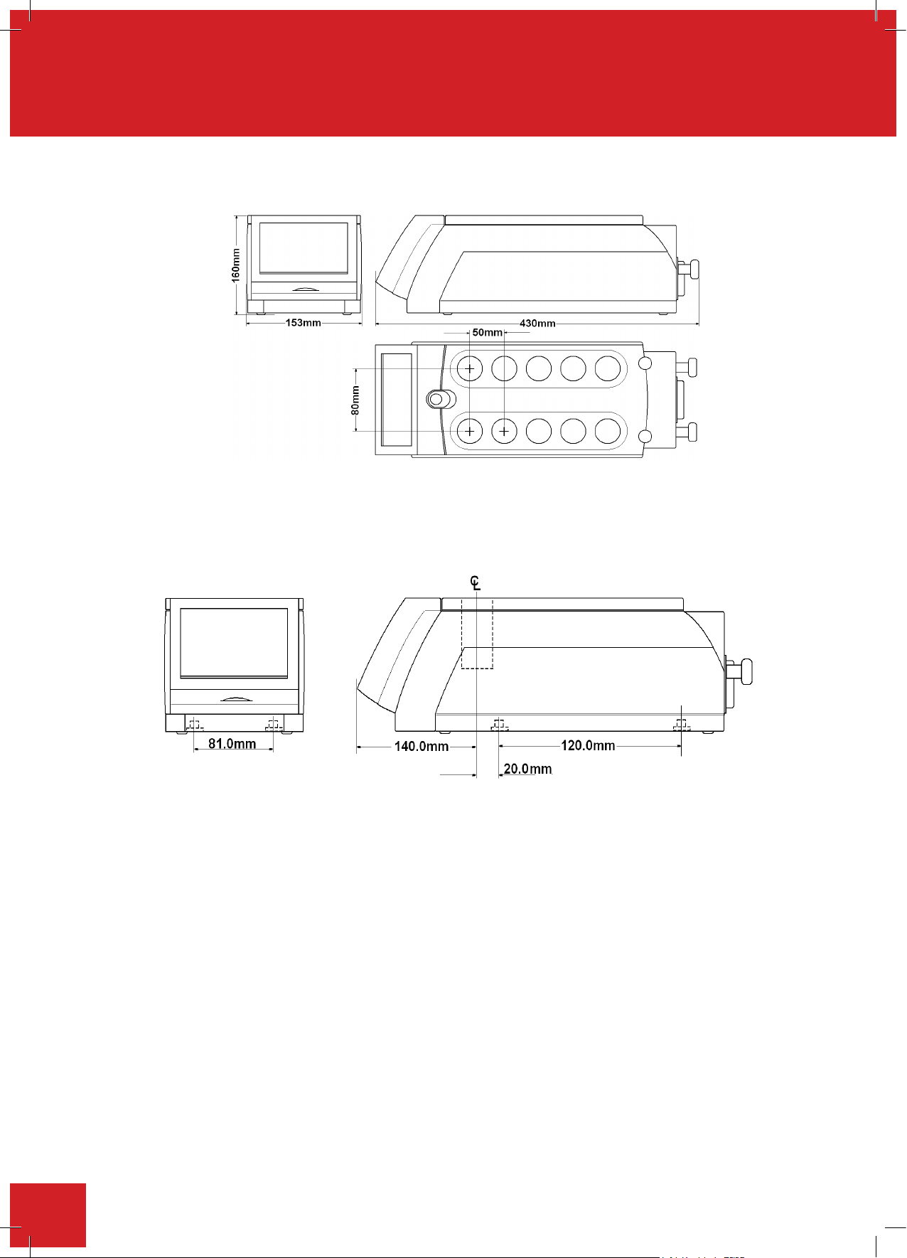
9. Reaction block dimensions
9. DIMENSIONS (UNIT)
Weight 9.5kg
Not to Scale
Location dimensions (For use in robotic stations)
Not to Scale
70
Page 71
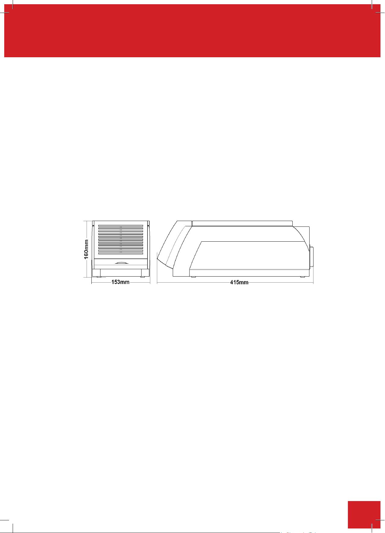
10. P
Mains in
put supply voltage
230/115/100V ~ AC ± 10% at 50/60Hz
Power Consumption 1500 max
Watts (2x750W)
Mains cord and moulded IEC plug
and lead s
et cable (UK) 16A BS1362
3 core earthed / ground. 2 meters long. Moulded
IEC plug and Lead set – supply cord H05 V V- F
– Replace only with equivalent cable.
Mains cord and moulded IEC plug
and lead s
et cable Schuko (Europe)
3 core earthed / ground. 2 meters long. Moulded
IEC plug and Lead set – supply cord H05 V V- F
– Replace only with equivalent cable.
Mains cord and moulded IEC plug
and lead s
et cable (USA)
3 core earthed / ground. 2 meters long. Moulded
IEC plug and Lead set – supply cord SJT V W 1
- 105° – Replace only with equivalent cable.
Lead set plug and fuse (UK – Only) 13A BS1362
Dimensions (PSU
)
owersupplyunit(PSU) specifications
Mains input supply voltage
Power Consumption
Mains cord and moulded IEC plug 3 core earthed / ground. 2 meters long. Moulded IEC
andleadsetcable(UK)16ABS1363 plugandLeadset–supplycordH05VV-F
Mains cord and moulded IEC plug 3 core earthed / ground. 2 meters long. Moulded IEC
and lead set cable Schuko (Europe) plug and Lead set – supply cord H05 V V- F
Mains cord and moulded IEC plug 3 core earthed / ground. 2 meters long. Moulded IEC
and lead set cable (USA) plug and Lead set – supply cord SJT V W 1 - 105°
Leadsetplugandfuse(UK–Only) 13ABS1363
Dimensions (PSU)
230/115/100V ~ AC ± 10% at 50/60Hz
Max 1500 watts
– Replace only with equivalent cable.
– Replace only with equivalent cable.
– Replace only with equivalent cable.
Weight 10.5kg
The Ingress Protection rating for the Integrity 10 Unit and power supply is IPX0.
Not to Scale
71
Page 72

11. Maintenance, service and repair
module – ATS10001 Optional)
Ensure the Integrity 10 is turned off before commencing the installation of Multitemp
module – ATS10001 Optional)
Ensure the Integrity 10 is turned off before commencing the installation of Multitemp
Use the Multitemp in conjunction with the Electrothermal operating instruction book supplied
with thi
s product.
ATTENTION.
Do not install the Multitemp on a surface which may become wet as the
Ensure the Integrity 10 is turned off before commencing the installation of Multitemp
Use the Multitemp in conjunction with the Electrothermal operating instruction book supplied
s product.
ATTENTION.
Do not install the Multitemp on a surface which may become wet as the
module – ATS10001 Optional)
Ensure the Integrity 10 is turned off before commencing the installation of Multitemp
Use the Multitemp in conjunction with the Electrothermal operating instruction book supplied
with thi
s product.
ATTENTION.
Do not install the Multitemp on a surface which may become wet as the
11.1. Maintenance
Unplug the unit from the mains voltage supply and allow it to cool before undertaking any
maintenance tasks.
Maintenance should only be carried out by an approved Cole-Parmer representative. Failure to do so
may result in
With proper care in operation this equipment has been designed to give many years of reliable service. Contamination
or general misuse will reduce the effective life of this product and may cause a hazard.
Maintenance for the Integrity Unit and Power Supply should include:
• Periodic electrical safety testing (an annual test is recommended as the minimum for the PSU).
AC dielectric withstand (Flash / Hi Pot) must not be undertaken on this equipment as damage may result. Such
testing will invalidate warranty.
DCdielectricwithstand(ash/HiPot)maybeappliedtothePSU only (i.e. The Integrity 10 unit must not be
connected when the PSU is being tested. The Integrity 10 unit operates at low voltage (15V DC) and must not
be subjected to dielectric withstand (Flash / Hi Pot) testing.
damage to the product and in extreme cases be a danger to the end user
DCdielectricwithstand(ash/HiPot)testingshallonlybeundertakenbycompetenttrainedpersonnelusing
suitable test equipment / environment. DC test voltage should be no more than 1.414 times normal AC test
value for a class I (grounded) equipment.
The test equipment / process should incorporate a discharge procedure to remove any stored DC charge that
may remain on the PSU.
• The Integrity PSU: Routine cleaning of the equipment should be undertaken using a water moistened, clean
cloth.
• The Integrity Unit: Side panels and drip tray may be cleaned using mild warm soapy water and must be
wiped dry before use. Do not use anything abrasive on the Touch LCD screen. Before cleaning the touch LCD
screen, ensure the unit is turned off and SD card removed. Clean the screen using PC screen wipes or a water
dampened, clean non-abrasive cloth.
DO NOT USE SOLVENTS OR ABRASIVE CHEMICALS FOR CLEANING ANY PART OF THIS EQUIPMENT.
ATTENTION. THERE ARE NO SERVICEABLE PARTS WITHIN THE INTEGRITY 10 POWER SUPPLY
– IF IN DOUBT CONSULT MANUFACTURE OR SUPPLIER.
72
Page 73

11.2. Spillage procedure
In case of solution spillage, turn off the Integrity 10 unit via the Power Supply On / Off switch. For light
spillage wipe off the solution using a water dampened cloth and dry thoroughly before further use.
For spillage involving liquid solution spilt into a reaction well, turn off the Integrity 10 unit via the
Power Su
pply On / Off switch. Turn off the chilled water supply and disconnect the supply hoses.
Uncouple and remove any peripheral cables linked to a PC or accessories. Remove mains power
input and mains connection cable.
Take the unit and tip any spillage out of the reaction cells
. (**) Clean the unit using a water dampened
cloth and dry thoroughly. Ensure the unit is dry before further use. The Responsible Body shall
check the electrical safety of the unit. Only if all safety requirements are met can the unit be
used again. The above procedure is intended as a guide. Should spillage occur with a toxic or
hazardous fluid then special precautions may be necessary.
(**) Observe special precautions for handling contaminated substances see Section 11.3
If the equipment has been exposed to toxic, radiological or biological contamination,
. (**) Clean the unit using a water dampened
In case of solution spillage, turn off the Integrity 10 unit via the Power Supply On / Off switch. For light spillage
wipe off the solution using a water dampened cloth and dry thoroughly before further use.
For spillage involving liquid solution spilt into a reaction well, turn off the Integrity 10 unit via the Power Supply
On / Off switch. Turn off the chilled water supply and disconnect the supply hoses. Uncouple and remove any
peripheral cables linked to a ble. PC or accessories. Remove mains power input and mains connection ca
Take the unit and tip any spillage
(**) out of the reaction cells taking care to support the unit on the block.
Do not place undue pressure on the front pod as this may damage the unit and invalidate any warranty.
Clean the unit using a water dampened cloth and dry thoroughly. Ensure the unit is dry before further
use. The Responsible Body shall check the electrical safety of the unit. If all safety requirements are
met the unit can be used again. The above procedure is intended as a guide. Should spillage occur
with a toxic or hazardous fluid then special precautions may be necessary.
(**) Observe special precautions for handling contaminated substances see Section 11.3 .
11.3. Decontamination
If the equipment has been exposed to toxic, radiological or biological contamination, the Responsible
Body is responsible for carrying out appropriate decontamination. If hazardous material has been spilt on
or inside the equipment, decontamination should only be undertaken under the control of the Responsible
Body with due recognitio
n of possible hazards. Before using any cleaning or decontamination method, the
Responsible Body should check with the manufacturer that the proposed method will not damage the equipment.
DECONTAMINATION CERTIFICATE
NOTE:
In the event of any part of this unit becoming damaged, the damaged item(s) should be returned to
the manufacturer for repair accompanied by a decontamination certificate. Copies of the Certificate are
availablefromDistributor/Manufacturer.Atthe endoflifethisproductmustbe accompaniedwitha
ontaminationCertificate.
Dec
11.4. Servicing
Please contact your local Cole-Parmer Technical Sales Specialist or contact:
E-mail:
Phone: +44 (0)1785 810475
11.5. Error and warning messages
Error and warning messages will be displ
ayed if the equipment status moves outside of the normal operating
limits. The message will indicate recovery instructions or service support actions as appropriate.
Error and warning messages have been included to help the user determine the state of malfunction. In some
instancesthemessagewilldisplayamethodforfaultconditionrectication.
When the warning symbol appears in a single cell button and the cell button turns red, touch the cell button to
display the fault condition.
73
Page 74
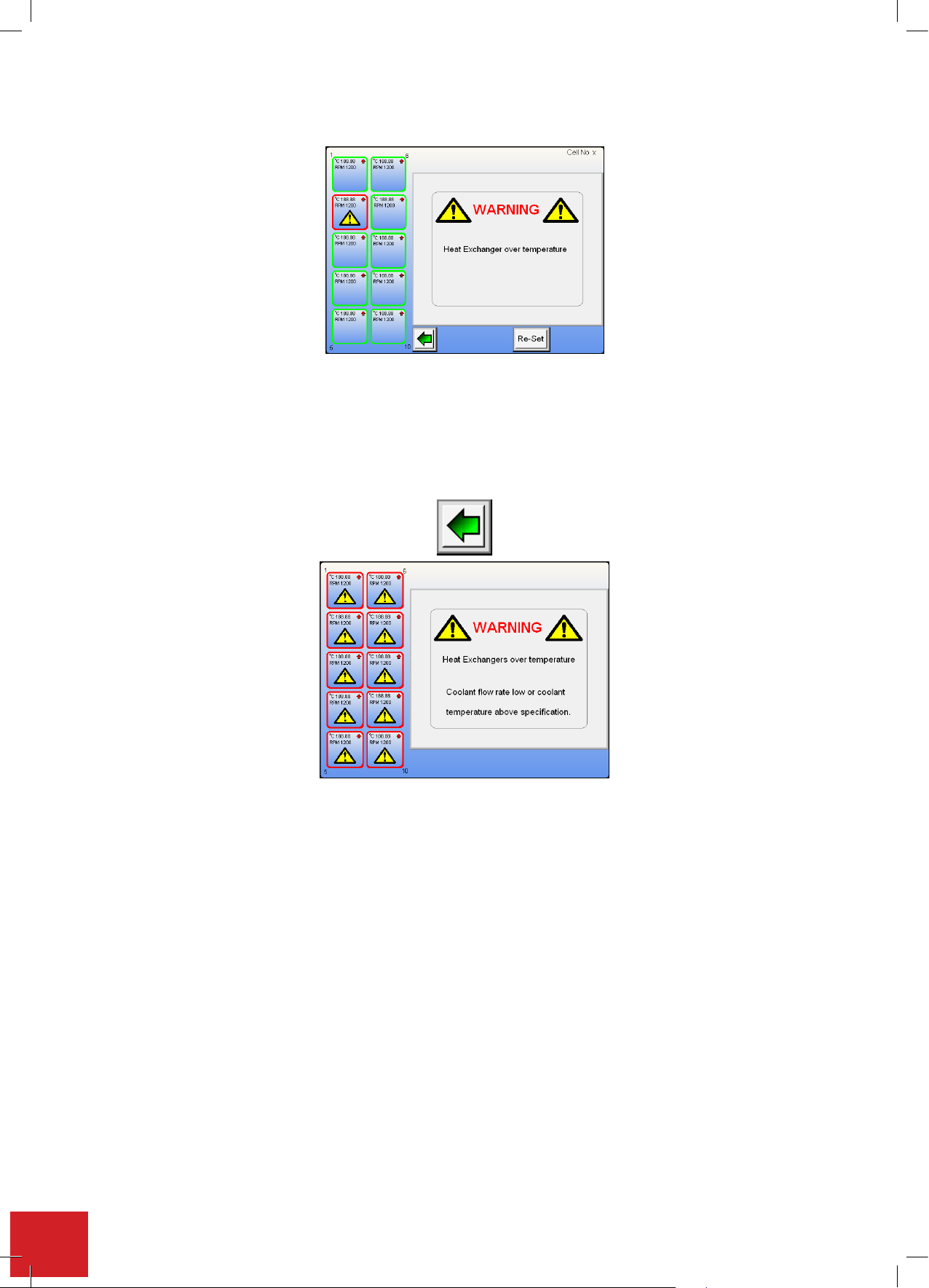
11.5.1. Heat exchanger over temperature error
This warning shows a fault condition with the cell number 2. Please contact the manufacturer or your distributor
for service support.
Ifallthecellsareaffectedanotherwarningmessagewillbedisplayed.Apossiblecauseforthisisablockedow
chamber in the cell heat exchanger. Check water coolant supply for debris contamination.
To return to the home screen and view the performance of other operational cells touch the back button.
Fromthisscreenitcanbeseenthatallcellsheatexchangersareaffected.Thisiscausedbythecoolantwaterow
rate being too low for the cells to operate or the coolant water temperature being too high (above 35°C).
IftheproblemiscausedbylackofwaterowratetheIntegrity10willshutdowntoprotectinternalpartsfrom
damage. Once chilled water has been restored the unit will automatically recommence operation and the warning
message screen will disappear.
If the problem is caused by the water temperature being too high the Integrity 10 will shut itself down as previously
mentioned in order to protect internal parts from damage. Again when the correct temperature chilled water is
restored the unit will recommence operation and the message screen disappears.
Possible reasons for chilled water becoming too hot include but are not exclusive to:
• Failed chiller unit.
• More than one appliance connected to the chiller system returning water at temperature greater than the
chiller can cope with.
•
Integrity 10 connected in series with another piece of equipment returning chilled water at a temperature
above 35°C
•
Low coolant flow rate which is insufficient to remove the heat from the heat exchangers (less than 5/L per minute).
See Appendix 'A'. Integrity cooling guide for more information
74
Page 75
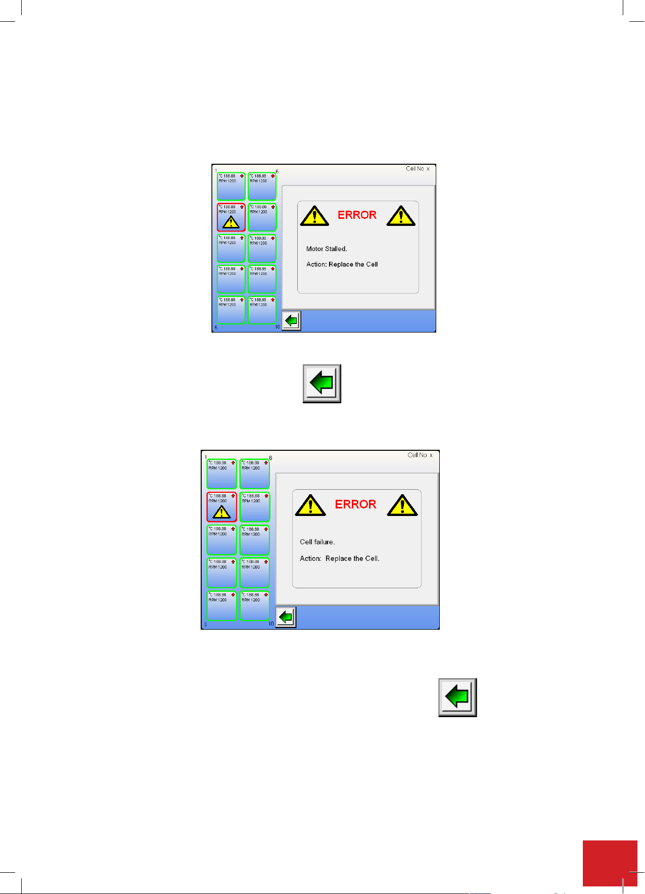
11.5.2. Motor stall error
°°°°
C.
°°°°
without a chilled water set at 5
°°°°
C
°°°°
C.
°°°°
without a chilled water set at 5
°°°°
C
°°°°
C.
°°°°
without a chilled water set at 5
°°°°
C
°°°°
C.
°°°°
without a chilled water set at 5
°°°°
C
This illustration screen shot shows a stir motor fault with cell position number 2. The cell position may still be used
in heating / cooling mode but the cell will not stir. The cell will have to be replaced.
Contact the manufacturer as detailed in section 12 customer support.
To return to the home screen and view the performance of other operational cells, touch the back button.
11.5.3. Cell failure error
This illustration screenshot shows a cell failure with cell position number 2. The cell will have to be replaced.
Contact the manufacturer as d
To return to the home screen and view the performance of other operational cells
touch the back button.
etailed in section 12 customer support.
75
Page 76
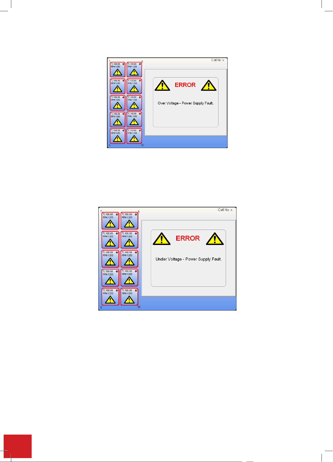
11.5.4. Over voltage error
This indicates a fault with the Power Supply Unit. Contact the manufacturer as detailed in section 12 customer
support. Turn off the Integrity 10 and disconnect from the mains electricity supply.
11.5.5. Under Voltage error
76
As above this indicates a fault with the Power Supply Unit. Contact the manufacturer as detailed in section 12
customer support. Turn off the Integrity 10 and disconnect from the mains electricity supply.
Page 77
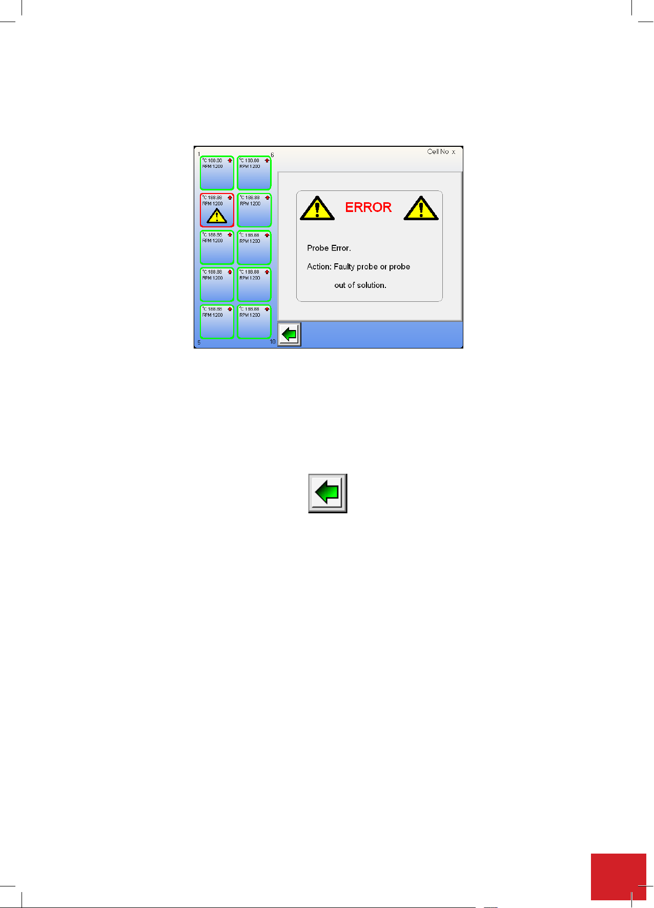
11.5.6. Probe error
If an external probe is being used and it is either left out of the sample solution or drops out of the sample solution
during a run, the following screen will appear if the probe is faulty.
When the Integrity unit senses a block temperature that is 20°C above the solution temperature this error condition
is created.
Oncethefaulthasbeenrectiedtouchthecellbuttonandselectmethodofoperation.
e.g.,manualorprolecontrolandrestartthecell.
To return to the home screen and view the performance of other operational cells touch the back button.
77
Page 78

12. Customer support
If you require further technical or application assistance please contact:
E-mail: [email protected]
Phone: +44 (0)1785 810433
For servicing information please contact:
Service Department
Cole-Parmer Ltd
Beacon Road
Stone
Staffordshire
ST15 0SA
E-mail: [email protected]
Phone: +44 (0)1785 810475
We are continually striving to improve our products and software. If you have any comments or suggestions on
how we can do things better please send them to us at:
E-mail: [email protected]
78
Page 79

13. Spares and accessories
ACCESSORIES
Order Number Quantity
ATS20100 1
ATS20002
ATS10075
ATS20003
ATS20004
ATS10001 1
ATS10027
ATS10027/10 1
ATS10232E
ATS10360/1 1
ATS10230 1
ATS10394/1 1
ATS11005 1
AZS4206
Description
Reflux
/ inertingblockforintegrity10
Inerting caps, SVL 22 thread for use with ATS20100, pack of 10
Glass tubes 24/150mm, SVL22 thread, pack of 10
Inertingcaps,KimblethreadforusewithATS20100, pack of 10
Glasstubes24/150mm,Kimblethread, pack of 10
Multi-Temp 12 plug in box
Temperature probes, pack of 6
Temperature probes, pack of 10
Multi-IR 10 plug in unit
Non-intrusive IR sensor
Small intrusive IR probe in stainless steel PID-NIR5-BNSD
Hellma intrusive IR probe with high chemical resistance
Integrity PC software
Stirrer bars 10/6mm oval shaped for round bottomed tubes, pack of 10
1
1
1
1
1
1
1
AZS4235
ATS10055
ATS10056 1
ATS10101
ATS10209
M7438
Stirrerbars12/4.5mmforflatbottomedtubes, pack of 10
Small volume test tubes 24-16mm taper (3ml), pack of 10
Reducing sleeves for ATS10055, pack of 10
Reducing sleeves 24 – 11mm, pack of 10
Micro-volume test tubes 24-11mm taper (1ml), pack of 10
Spare coolant supply hoses
1
1
1
1
2
Please contact your local sales specialist or email [email protected] to enquire about available spares.
Please visit www.electrothermal.com for a full list of available accessories.
79
Page 80

14. Notes
80
Page 81
15. EU Declaration of conformity
This product meets the applicable
harmonized standards for radio frequency
interference and may be expected not to
interfere with, or be affected by, other equipment with
similar qualifications. We cannot be sure that other
equipment used in its vicinity will meet these standards
and so we cannot guarantee that interference will not
occur in practice. Where there is a possibility that injury,
damage or loss might occur if equipment malfunctions
due to radio frequency interference, or for general
advice before use, contact the manufacturer.
EU Declaration of Conformity
Product
Manufacturer
This declaration of conformity is issued under the sole responsibility of the manufacturer
Object of Declaration
Laboratory Equipment
Cole-Parmer Ltd
Beacon Road
Stone, Staffordshire
ST15 0SA
United Kingdom
Integrity 10 Reaction Station
(reference the attached list of catalogue numbers)
File Number
Authorised
Representative
P225
Cole-Parmer
Beacon Road
Stone, Staffordshire
ST15 0SA
United Kingdom
The object of the declaration described above is in conformity with the relevant Union Harmonisation Legislation:
Low Voltage Directive 2006/95/EC
2014/35/EU
EMC Directive
RoHS Directive
References to the relevant harmonised standards used or references to the other technical specications in relation
to which conformity is declared:
Safety requirements for electrical equipment for
IEC/EN 61010-1:2010
IEC/EN 61010-2-010:2014
IEC/EN 61010-2-051:2003
IEC/EN 61326-1:2006
Signed for and on behalf of the above manufacturer
Additional Information
Place of Issue
Date of Issue
Authorised Representative
Title
Signature
measurement, control and laboratory use.
Part 1: General requirements.
Particular requirements for laboratory equipment for the
heating of materials.
Particular requirements for laboratory equipment for
mixing and stirring.
Electrical equipment for measurement, control and
laboratory use. EMC requirements.
Part 1: General requirements (Class A).
Year of CE Marking: 2010
Stone, Staffordshire, UK
18 May 2011. Revised 29 September 2017
P Day
General Manager
2004/108/EC
2011/65/EC
(until 19 April 2016)
(from 20 April 2016)
Declaration of Conformity is also available to view online at www.electrothermal.com
81
Page 82
Cooling Guide
THE INTEGRITY 10 COMPANION GUIDE
The Integrity 10 reacon staon must be used with an appropriately rated cooling system at all
mes, even when the equipment is only used for heang applicaons.
Failure to use an appropriately rated cooling system will negavely impact the performance of
the Integrity 10. In some circumstances this could reduce the life of the product, increase
service frequency or cause permanent damage.
Damage caused to the Integrity 10 through the use of inappropriately rated cooling systems is
ot covered under warranty.
n
Damage caused to the Integrity 10 through the use of unfiltered or contaminated coolant is
not covered under warranty.
Integrity 10 Cooling Requirements
The Integrity 10 is capable of independently cooling each of its 10 cells down to a minimum
temperature of -30°C, but this is only achievable when the product is coupled to a cooling system that
can remove heat at a rate g
It is important to understand the importance of this relaonship and to select an appropriate cooling
system so that you can achieve the performance needed for your applicaon and get the results you
expect.
reater or equal to that collected by the Integrity.
Understanding the systems relaonship
Each of the Integrity’s cells contain a cooling device (the TEC). While operang in cooling mode, these
devices remove heat from the reacon vessel and pass it onto the cooling system via a heat exchanger.
The temp
by the chiller and rejected into the air.
erature of the coolant increases which is the
It is important to note that even when a cell is heang and not using the cooling feature, a
cooling system is sll required to ensure damage is not sustained to the sensive cells during
operaon.
n pumped out of the Integrity, where it’s cooled
82
When appropriately matched, the cooling system and Integrity work in harmony and are able
to achieve the performance expected.
If inappropriately matched, the cooli
upon it. In this situaon, the cooling performance of the Integrity is negavely impacted
reducing the rate of cooling and/or liming the minimum temperature the cell is able to
achieve.
ng system is unable to kee
p up with the demands placed
Page 83

THE INTEGRITY 10 COMPANION GUIDE
In extreme circumstances i.e. when a cooling system is severely under-rated, the chillers reservoir of
coolant will progressively increase in temperature unl the cooling system displays an error message
and potenally stops operaon.
Managing the load on the cooling system
Knowing how to manage the load placed upon your cooling system will help you achieve the
performance you require and will also help you save energy.
There are three main factors which contribut
o The number of cells being cooled at any me.
o The cooling rate selected.
o The minimum temperature required.
Example 1
Cooling 10 cells in parallel places a higher load on the cooling system than only cooling 2 cells in parallel.
Example 2
Cooling at a rate of 5°C/minute places a higher load on the cooling system than cooling at 1°C/minute.
Example 3
Cooling down to a temperature of -30°C places a higher load on the cooling system than cooling down
to a temperature of -10°C.
In a worst case scenario, an expe
uncontrolled ramping profile. Uncontrolled ramping is when a user hasn’t specified a ramp-rate in the
Integrity sengs. In this situaon, both the Integrity and cooler will need to work their hardest to reach
the desired temperature.
The Integrity is easily capable of cooling all 10 cells down to a temperature of -30°C, provided it is
coupled to an appropriately rated cooling system. The me taken to reach a temperature of -30°C using
uncontro
mping is subjecve and dependant on:
lled ra
rimen
e to the load on the cooling system:
t would demand all 10 cells to cool to -30°C in parallel, using an
The performance capabilies of the cooler.
The ambient temperature in the laboratory.
The contents of the vessel and its heat capacity (i.e. the amount of energy which must be
removed from the contents in order to yield a measurable temperature change).
The nature of the experiment being performed (e.g. exothermic reacons).
83
Page 84

THE INTEGRITY 10 COMPANION GUIDE
Reducing the load on the cooling system
If you believe your system is struggling to meet the performance demands placed upon it, consider the
following list of suggesons to help reduce the load on the system:
Increase the temperature of the experiment.
Reduce the number of cells which are cooling in parallel.
Ensure your cooling system is regularly serviced and is maintained in line with the
manufacturer’s recommendaons.
Ensure the coolers condenser is clean and has unrestric
Ensure coolant is clean with no contaminates which can block the Integrity heat exchangers.
Reduce the cooling ramp-rate of the experiment.
Reduce the ambient temperature of the laboratory using air condioning.
A good indicaon that your cooling system is under-rated for your experiment is when you observe a
temperature plateau when working below ambient temperatures.
For example: You set up the Integrity to cool all 10 cells down to a temperature of -20°C however
you noced that the cells have
demands placed upon it because the rate at which heat is gathered by the Integrity
now matches the capability of the cooler. (You may also observe an undulaon in the
minimum temperature as the coolers compressor cycles on and off in an aempt to
maintain the coolants temperature.)
only reached -15°C. The cooler is struggling to meet the
ted air-flow.
Selecng a cooling system
Now that we’ve explained the relaonship between the Integrity 10 and the cooling system, we shall
discuss the important specificaons of
There are four primary consideraons when selecng a cooling system:
1 Working temperature range
The first parameter to consider when selecng your recirculang cooler is the working temperature
range. In order for the Integrity to reach a minimum temperature of -30°C, the cooler will need to be
capable of working between 5°C and -5°C.
The working temperature you use will be subjecve to your experiment and is typically determined
empirically. We recommend you start at
you achieve the performance required.
Tip: Don’t set your chiller cooler than needed - it is always best pracce to use the
warmest working temperature possible which achieves your performance
requirements to avoid unnecessary condensaon and to avoid wasng energy.
2 Cooling Capacity
The cooling capacity is a characterisc which determines how quickly the cooler can remove the heat
collected by the Integrity. As menoned previously, th
that of the Integrity, so that the performance of the whole system can be comfortably maintained.
the cooling system.
5°C and progressively reduce the coolers temperature unl
e cooler needs a capacity greater or equal than
84
It is recommended that you select a product with a cooling capacity of at least 1.1KW (1100W) between
the working temperature of range of 5 to -5°C. With this cooling capacity, you will be able to use the
Integrity 10 to its maximum potenal.
Page 85

THE INTEGRITY 10 COMPANION GUIDE
Most manufacturers of recirculang coolers typically specify the cooling capacity of their equipment
using a table, because there is a relaonship between working temperature and cooling capacity of
such systems.
For example, see the ficous table below:
Working temperature (°C) 20 10 0 -10
Cooling Capacity (kW) 2.5 1.8 1 0.4
As you can see from this table, the cooling capacity decreases significantly as the working temperature
is reduced.
It should be noted that manufacturers of recirculang coolers would adverse this system as a
nominal 2.5kW system. This is in fact the cooling capacity at 20°C only. You should always determine
the cooling capacity over the recommended working temperature range of the Integrity.
It’s possible to run the Integrity using a lower rated cooling capacity, although this isn’t recommended.
Please see the next sec
on on ‘lower rated systems’ for more informaon about this.
3 Flow Rate
The cooler should be capable of providing coolant at a rate of at least 5 Litres per minute, directly into
the Integrity.
If you are sharing your cooling system with other equipment or accessories, you must ensure that the
supply of 5 Litres per minute is maintained for the duraon of your work.
Do not compromise the flow rate of the coolant into the Integrity by using incorrectly specified
ancillary items such as couplers, reducers or te
eces, for example.
e-pi
4 Pressure
In order to obtain the flow rate discussed above, the coolers pump must be capable of providing a
pressure of at least 2 bar.
If you are sharing your cooling system with other equipment or accessories, you must ensure that the
pressure of at least 2 bar is maintained for the duraon of your work.
Lower rated systems
It is not recommended that you use the Integrity with a lower rated system than explained above. If
you do, you will not necessarily be ab
nor will you be able to exploit the full potenal of the Integrity 10 and cool all cells down to a minimum
temperature of -30°C
le to reach the performance characteriscs required by your work
85
Page 86

THE INTEGRITY 10 COMPANION GUIDE
Filtering requirements
When coupling your Integrity 10 to a cooling system it is required that you also fit a 50 micron inline
filter (if one is not present in the cooler) to prevent the ingress of contaminates into the cell heat
exchangers. The filter should be installed on the outlet of the chiller.
Paral restricon or blockage of heat exchangers caused by contaminates will impact the system
performance and potenally void your warranty.
Summary of cooling system specificaon
Working temperature range 5 to -5°C
Cooling Capacity 1.1kW (1100W) between 5°C to -5°C
Flow Rate ≥ 5 Litres per minutes
Pressure ≥ 2 bar
Inline Filter 50 micron
Table 1 - Recommended specificaon of Integrity 10 cooling system
Circulang Fluids
Once you have selected your cooling system, you will need to follow the manufacturer’s
recommendaon and use a fluid suitable for your applicaon. Manufacturers will recommend avoiding
an-freeze intended for cars, instead prompng use of fluids designed specifically for lab equipment.
When working with refrigerated and other cooling equipment, it is important to use a fluid that will not
freeze because the temperatu
temperature.
Circulang Fluids – Cooling
Water-based synthec fluids are popular choices for cooling. They can be used across a broad
temperature range, especially when used in sealed or vacuum systems. Glycols, when mixed with water,
become anfreeze. This does not mean that you can buy and use automove anfreeze. What’s good
for your car is not necessarily good for your lab equipment. There are tw
used: Ethylene glycol (EG) and propylene glycol (PG). Of the two, EG has slightly beer thermal
properes and can cool in a broader temperature range. However, it is highly toxic and not usable in all
applicaons. In those cases, PG is a good alternave. We recommend mixing with dislled water; the
best mix rate is 50/50.
Circulang Fluids – Mixes
Mixes are offered as a convenience and are made up of one or more of the fluids, described above, like
a mix of ethy
filling common-sized equipment like chillers.
lycol, water and algaecide. They are usually sold in volumes that make sense for
lene g
re inside the cooling equipment may be significantly colder than the set
o g
lycols which are commonly
86
Page 87

87
Page 88

Cole-Parmer Ltd.
Beacon Road,
Stone,
Staffordshire,
ST15 0SA,
United Kingdom
Tel: +44 (0)1785 812121
Email: [email protected]
Web: www.electrothermal.com
 Loading...