

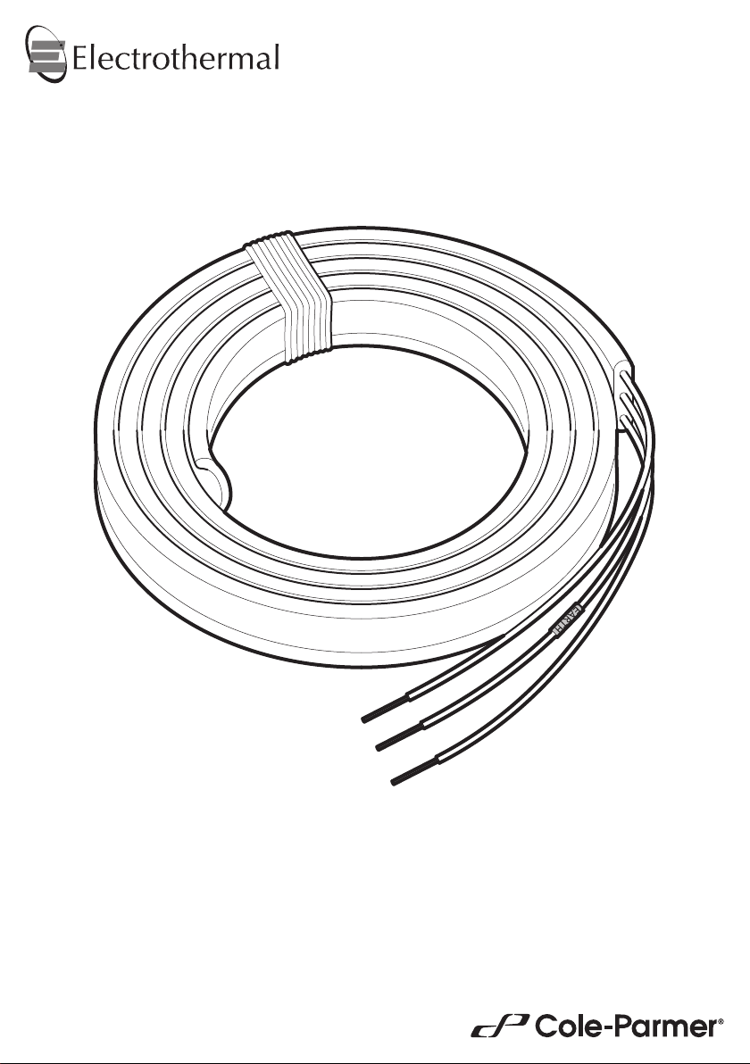
Heating Tape
Instruction Manual
ET0002 / Version 1.1
Contents
Introduction 3
General Description 3
Important Safety Advice 4
Electrical Requirements 4
Before Use 5
Prepare Surface 5
Visual Inspection and Handling 5
Installation / Tracing 6
Applying Insulation (Optional) 6
Selecting a Control System 7
External Temperature Controller 7
Thermostats and Sensors 7
Digital Display Controller 7
Proportional and PID Control Systems 7
Connecting to a Power Supply 7
Operation 8
Cleaning and Care 8
In Case of Accidental Spillage 8
In Case of Contamination 8
Service 9
Warranty 9
Spares and Accessories 9
Technical Specication 10
Customer and Technical Support 10
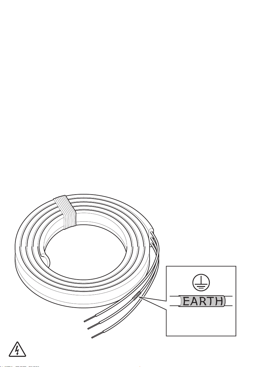
(Grounded)
NOTE: Heating Tapes are supplied with bare wires and MUST be connected to an external temperature
control device (not included) and protected by an adequate circuit breaker or fuse.
2
Introduction
Thank you for purchasing this Electrothermal product. To get the best performance from the
equipment, and for your own safety, please read these instructions carefully before use.
Before discarding the packaging check that all parts are present and correct.
This equipment is designed to operate under the following conditions:
v For indoor use only
v Use in a well ventilated area
v Ambient temperature range 5°C to 40°C (41°F to 104°F)
v Altitude to 2000 m (6500 ft)
v Relative humidity not exceeding 80%
v Mains supply uctuations not exceeding 10% of nominal
v Overvoltage category II IEC60364-4-443
v Pollution degree 2 IEC664
v Use with a minimum distance all round of 200 mm (8 in.) from walls or other items
If the equipment is not used in the manner described in this manual and with accessories other than
those recommended by the manufacturer, the protection provided may be impaired.
General Description
Electrothermal Heating Tapes are a range of exible resistance heater elements for use in a wide range of
commercial/industrial surface heating applications. The exible heaters are ideal for heating columns, pipes, valves
and transfer lines.
All tapes are constructed of an element covered in glass bre and a braided earth (ground) wire which is enclosed
in a glass sleeve. Lengths range from 61cm (2ft.) to 976cm (32ft.) with a linear loading of 50W/ft (164W/M).
Heating tapes are available in 120 V and 230 V versions up to 488cm (16ft.) and in 230 V only for 732cm (24ft.)
and 976cm (32ft.) lengths. Product is suitable for use in dry conditions only, is not water resistant and has a
maximum element temperature of up to 450°C and has a minimum helix diameter of 50mm (2 in.).
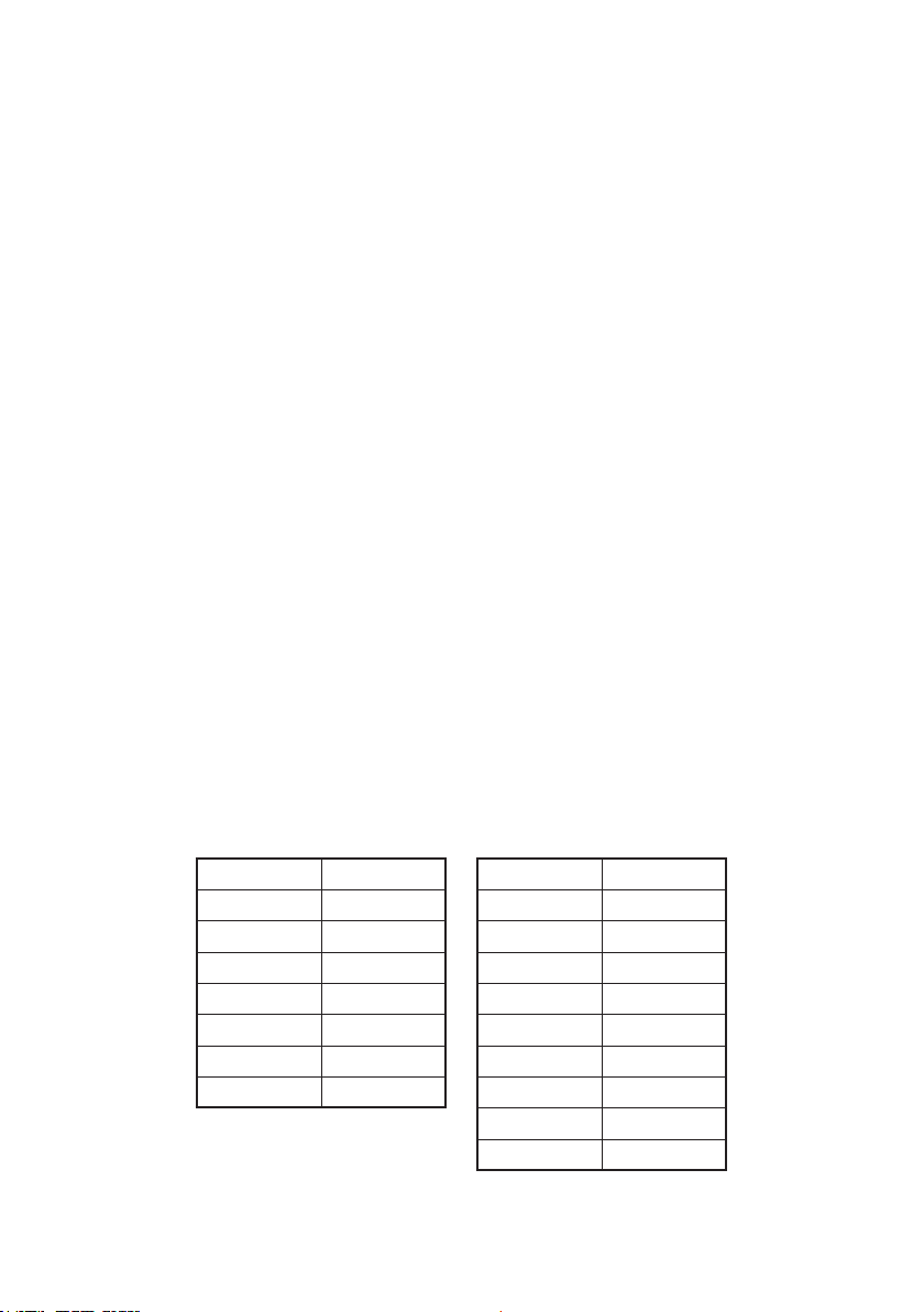
The following tables identify the different sizes and groups within the Heating Tape range:
120 V Models Length 230 V Models Length
HT95502X1 61cm (2ft.) HT95502 61cm (2ft.)
HT95503X1 91cm (3ft.) HT95503 91cm (3ft.)
HT95504X1 122cm (4ft.) HT95504 122cm (4ft.)
HT95506X1 183cm (6ft.) HT95506 183cm (6ft.)
HT95508X1 244cm (8ft.) HT95508 244cm (8ft.)
HT95512X1 366cm (12ft.) HT95512 366cm (12ft.)
HT95516X1 488cm (16ft.)
HT95516 488cm (16ft.)
HT95524 732cm (24ft.)
HT95532 976cm (32ft.)
3
Important Safety Advice
Users should be aware of the following safety advice:
v SHOCK HAZARDS OR UNSAFE PRACTICES ARE DANGEROUS as they can cause severe personal injury, re
or death.
v DO NOT expose the element to liquids.
v DO NOT use combustible substances near hot objects.
v DO NOT use the equipment in hazardous atmospheres.
v DO NOT attempt to shorten, cut or allow sharp metal objects near the element.
v DO NOT operate or handle any part of the product with wet hands or use on surfaces that may become ooded.
v DO NOT overlap, kink, pinch or twist the heating tape or allow any portion to sag from the surface.
v DO NOT use worn or damaged elements or attempt to repair the element.
v NEVER move the product while still connected to the power supply.
v NEVER connect product directly to the mains supply, these are designed for use with an external temperature
controller.
v ALWAYS use with protective earth (ground) bonded installation when applied to electrically conductive vessels.
v HIGH TEMPERATURES ARE DANGEROUS as they can cause serious burns to operators and ignite
combustible material. Users should be aware of the following safety advice:
v USE CARE AND WEAR PROTECTIVE GLOVES TO PROTECT HANDS.
v NEVER lift or carry the instrument until it has been switched off and allowed to cool.
v DO NOT position the element such that it is difcult to disconnect it from the power supply.
v DO NOT leave equipment switched on and it is not recommended to leave any heating apparatus unattended
during operation.
v DO NOT apply severe physical stress or use at temperatures above the rated value.
v NOT RECOMMENDED for use on plastic pipes.
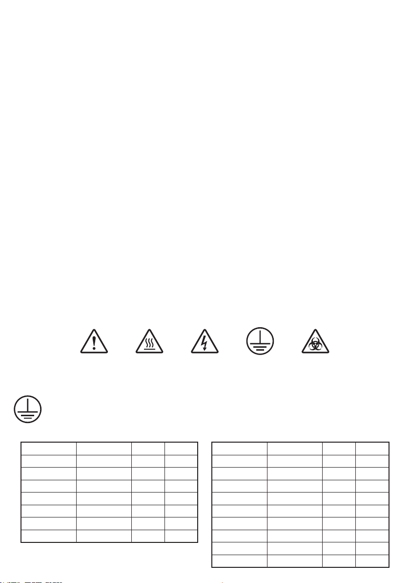
Symbols Dened
WARNING EARTH BIOHAZARDRISK OF
HOT
SURFACE
ELECTRIC SHOCK
Electrical Requirements
THIS INSTRUMENT MUST BE EARTHED/GROUNDED
Before connection please ensure that the line supply corresponds to the power requirements below:
120 V Models Length Volts Watts 230 V Models Length Volts Watts
HT95502X1 61cm (2ft.) 120 V 100W HT95502 61cm (2ft.) 230 V 100W
HT95503X1 91cm (3ft.) 120 V 150W HT95503 91cm (3ft.) 230 V 150W
HT95504X1 122cm (4ft.) 120 V 200W HT95504 122cm (4ft.) 230 V 200W
HT95506X1 183cm (6ft.) 120 V 300W HT95506 183cm (6ft.) 230 V 300W
HT95508X1 244cm (8ft.) 120 V 400W HT95508 244cm (8ft.) 230 V 400W
HT95512X1 366cm (12ft.) 120 V 600W HT95512 366cm (12ft.) 230 V 600W
HT95516X1 488cm (16ft.) 120 V 800W
4
HT95516 488cm (16ft.) 230 V 800W
HT95524 732cm (24ft.) 230 V 1200W
HT95532 976cm (32ft.) 230 V 1600W

THIS OPERATION SHOULD ONLY BE UNDERTAKEN BY A QUALIFIED ELECTRICIAN.
NOTE: Refer to the equipment rating label to ensure that the plug and fusing are suitable for the
voltage and wattage stated.
NOTE: Only qualied personnel are allowed to connect the electrical wiring. Installation must follow electrical
codes and nal inspection by the appropriate local authority.
NOTE: The end-user is responsible for providing suitable electrical protection device and disconnecting device. It is
recommended this unit be connected to a mains supply source which incorporates an RCD (residual
current device) or GFCI (ground fault circuit interrupt) device.
NOTE: This product requires the use of a temperature control device (not included). For example, the
Electrothermal MC controller range (optional purchase) is supplied with a moulded cord and plug set
wired as follows:
The wires in the power cable (120 V) The wires in the power cable (230 V)
are coloured as follows: are coloured as follows:
BLACK - HOT/LIVE BROWN - HOT/LIVE
WHITE - NEUTRAL BLUE - NEUTRAL
GREEN – EARTH GREEN/YELLOW – EARTH
IF IN DOUBT CONSULT A QUALIFIED ELECTRICIAN
The appropriate controller and power cable should be connected BEFORE connection to the power supply.
Before Use
Please refer to the installation instructions and safety advice and ensure the heating tape selected is of a suitable
length and power to t the application.
Prepare Surface - All vessels and pipes must be checked for sharp edges and cleaned prior to installation. Valves,
unions, sharp edges or other ttings can create air spaces and prevent good physical contact of the heater. Any
edges or gaps should be rounded off by the use of foam pads or compressed aluminium foil and can be xed in
place with glass fabric adhesive tape.
NOTE: The external temperature controller should be xed into place prior to applying the heater.
Visual Inspection and Handling - After removing from the packaging, visually inspect the heater tape for any
damage. Ensure the heater physically ts the desired pipe or vessel, will be in good contact with the surface and
will not overlap itself when installed. Heating tapes are manufactured from glass, ceramic and quartz bres, and
can be easily damaged by poor handling during installation. Care must be taken to ensure there is no twisting
or crushing of the loose length of tape during the placement. Any tight bend or twist in the heater may result in
rupture or separation of the outer layers of glass yarns and a live element wire may protrude.
NOTE: It is highly recommended that any installation involve two persons for proper handling.
5

Installation / Tracing
Heating tapes offer a wide range of exibility for controlling the temperature of variable size and odd geometry
items. To aid the installation process, do not x any parts of the heater in place (other than at the start and nish)
until the spiral winding is even and in proper contact over the entire length.
Lower temperatures may be achieved by a simple straight tracing and xing at 15cm (6 in.) intervals (e.g., taping
the heater along the underside of a pipe), see Figure 1.
Higher temperatures may be achieved by spiralling the heater around the desired pipe or vessel with glass fabric
adhesive tape xed in 15-25cm (6-10 in.) intervals, see Figure 2 & 3.
WARNING: Do not allow the tape to overlap, see Figure 4.
Figure 1
15cm (6in.)
Figure 3
Applying Insulation (Optional)
Most heating systems will benet from additional thermal insulation, which should be selected to suit the temperatures required. Well tted insulation decreases heat loss and cover and supports the heater over the whole
area. Traditional insulation materials or brous insulation, such as wool and ceramic bre may also be cut to size,
enveloped in aluminium foil and the taped into place. In general terms, the thicker the insulation layer, the more
efcient the heater will be.
Figure 2
Figure 4
Incorrect Installation
Insulation materials may be considered as follows:
Required Temperature Insulating Materials Thickness
Up to 80°C (176F) PVC/Nitrile rubber foam 10mm (½in.) brous insulation
100 to 180°C (212-356F) Silicon Rubber foam 25mm (1in.) brous insulation
180 to 400°C (356-752F) Rockwool, Glassbre 50mm (2in.) brous insulation
400 to 750°C (752-1382F) Ceramic bre blanket 75mm (3in.) brous insulation
NOTE: Large amounts of brous insulation may absorb moisture when cold and trip circuit breakers.
6

Selecting a Control System
Any heating system will only be as good and reliable as the control system permits. Various types of control are
available and outlined below:
External Power Controller (e.g. Electrothermal MC5*, MC227*, MC228*) - Based upon thermal simmerstats
or various types of solid state power control devices. Adjustable rate of energy ow based upon a dial with a pointer
on arbitrary scale. Monitoring of temperature is essential, adjustment may be frequent, or temperatures will drift.
WARNING: These devices should NEVER be used unsupervised or in any circumstances where excess
temperature could create an unsafe or hazardous situation.
Thermostats and Sensors - Bimetal contact switches, capillary and bulb mechanical thermostats may be used
but accuracy is likely to be only +/- 5%. Electronic thermostats offer improved accuracy, usually +/- 1°C, and use
a sensor mounted on the pipe or in the vessel. Thermocouples or resistance sensors should be selected to suit the
maximum temperatures involved, to be as small as possible, to give fastest response to changes, to be electrically
and physically isolated from the heater and rmly xed to the surface of the pipe or vessel if temperature
maintenance is required OR inserted into the uid/solid matter if process heating is required.
Digital Display Controller (e.g. Electrothermal MC810B*) - An external temperature controller with a digital
display and the capacity to pre-programme settings is the best solution for simple and accurate temperature
control in non-volatile and non-hazardous applications. They may also be used as an over-temperature device in
more sophisticated control systems when heating delicate, volatile or more hazardous substances.
Proportional and PID Control Systems - Delicate materials that require heat input whilst owing through the
system will require a more sophisticated control system.
* For connection instructions, please visit: www.electrothermal.com
NOTE: Need help selecting a control system? Please contact Electrothermal Technical Support for additional advice.
Connecting to a Power Supply
Installation must be by a competent electrician under the direction of the Responsible Body, so that a full
knowledge of operational and safety requirements is understood. Installation should be in compliance with all
current mandatory regulations.
This product MUST be connected to an external temperature control device (not included) and protected by an
adequate circuit breaker or fuse. The end-user is also responsible for providing a suitable electrical protection
device and disconnecting device. It is recommended this unit be connected to a mains supply source which
incorporates an RCD or GFCI device.
WARNING: Failure to operate the heater at the specied rating and/or with the required controller
could result in overheating resulting in re, burns or other personal injury and loss of property.
Before installation by a qualied electrician, please ensure the following:
v All metal parts are Protective Earthed (Grounded) to an approved and tested bonding point.
v All heaters are fused or protected by overcurrent circuit breakers of appropriate rating.
v All connecting cables meet the current and temperature requirements of the application.
v Provision has been made to switch off and isolate heating control circuits before installation.
v Provision for additional safety in the form of a residual current device tted to the incoming supply should be
considered.
7

Operation
Operation of the heating tape will be as per the instructions for the external controller. It is recommended that
once installation is complete and approved for use by a Responsible Body, that written instruction for use be
produced as part of the standard operational procedure documentation.
NOTE: Always install mechanical guards and thermal insulation to protect operatives and adjacent equipment.
NOTE: Heating systems can degrade with use. It is essential that regular inspections are carried out and
maintenance or replacement of system parts is completed as soon as required.
WARNING: Once the heating element has been installed and energised, the element will set to the
form of the enveloped surface. Any attempt to remove the unit after energising will damage the
heating element and make it unsafe to use.
Cleaning and Care
HOT: Before attempting cleaning, ensure that the unit is cool, and disconnect from the power supply.
WARNING: Ensure the unit is disconnected from the power supply before attempting maintenance or
servicing.
With proper care and operation, the equipment should give reliable service, however contamination or general
misuse may reduce the effective life of the product and could cause a hazard.
Preventative maintenance should include keeping the product clean by protecting it from spillage, contamination
or corrosive environments. If in doubt, please conrm that any intended method of decontamination will not
damage the equipment by contacting Cole-Parmer.
NOTE: Do not use solvents for cleaning any parts of this equipment.
In Case of Accidental Spillage
WARNING: DO NOT TOUCH IF A SPILLAGE/BREAKAGE HAS OCCURRED. DISCONNECT THE
POWER DIRECTLY AT THE POWER SUPPLY SOURCE.
If the equipment has been exposed to liquid, it cannot be assumed to meet all the safety requirements of EN
61010-2-010 until the drying out process has been fully completed and all safety requirements are met before the
unit is used again.
In Case of Contamination
WARNING: THE FOLLOWING PROCEDURE IS INTENDED AS A GUIDE. SHOULD SPILLAGE OF A
TOXIC OR HAZARDOUS FLUID OCCUR, THEN ADDITIONAL SPECIAL PRECAUTIONS MAY
BE NECESSARY.
8

If the equipment has been exposed to contamination, the Responsible Body is responsible for carrying out
appropriate decontamination. If hazardous material has been spilt on or inside the equipment, decontamination
should only be undertaken under the control of the Responsible Body with due recognition of possible hazards.
Before using any cleaning or decontamination method, the Responsible Body should check with the manufacturer
that the proposed method will not damage the equipment. Prior to further use, the Responsible Body shall check
the electrical safety of the unit. Only if all safety requirements are met can the unit be used again.
NOTE: In the event of this equipment or any part of the unit becoming damaged or requiring service,
the item(s) should be returned to the manufacturer for repair accompanied by a decontamination
certicate. Copies of the Certicate are available from the Distributor/Manufacturer.
At the end of its service life, the product must be accompanied by a Decontamination Certicate.
Servicing and Repair
This product range does not require any routine servicing, but in case of accidental spillage, instructions for
cleaning and decontamination are also included. Routine maintenance should include inspection of the power
supply unit and mains power lead set.
NOTE: There are no internal user replaceable parts.
NOTE: Periodic electrical safety testing is recommended on a yearly schedule or immediately after any servicing to
ensure safe operation.
In the event of product failure, heating tapes CANNOT be repaired. Fitting of non-approved parts may affect the
performance of the safety features of the instrument.
If in doubt, please contact:
Cole-Parmer Ltd.
Beacon Road,
Stone, Staffordshire,
ST15 0SA, United Kingdom
Tel: +44 (0)1785 812121
Email: cpservice@coleparmer.com
Web: www.coleparmer.com
Warranty
Cole-Parmer Ltd. warrants this equipment to be free from defects in material and workmanship, when used under
normal laboratory conditions, for a period of one (1) year. In the event of a justied claim, Cole-Parmer will replace
any defective component or replace the unit free of charge.
This warranty does NOT apply if:
v Any repair has been made or attempted other than by the manufacturer or its agent.
v Any minor coating chips or scratches occur during normal use (i.e., wear and tear).
v Damage is caused by re, accident, misuse, neglect, incorrect adjustment or repair, damage
caused by installation, adaptation, modication or tting of non-approved parts.
9

Technical Specication
Voltage 120 V or 230 V @ 50/60 Hz
Applications Dry Metal or Glassware
Max element temperature 450°C (842°F)
Linear loading 164 Watts per meter (50 Watts per foot)
Surface loading 0.62 Watts/cm² (4 Watts/in²)
Connection type Two Bare Wires plus Earth (Ground) Lead length 3.5in (9cm)
Dimensions Variable length x 25.4 cm (1 in.) width
Electrical supply See Power Requirements under Electrical Requirements section on page 4.
Customer and Technical Support
For help and support, contact:
Cole-Parmer Ltd. Customer Services: cpinfo@coleparmer.com
Beacon Road, Sales: cpsales@coleparmer.com
Stone, Staffordshire, Technical Support: cptechsupport@coleparmer.com
ST15 0SA, United Kingdom Warranty, Repairs and Service: cpservice@coleparmer.com
Tel: +44 (0)1785 812121 Web: www.coleparmer.com
For the America’s, contact:
Cole-Parmer Customer Services: sales@coleparmer.com
625 East Bunker Court, Sales: sales@coleparmer.com
Vernon Hills, Technical Support: techinfo@coleparmer.com
IL 60061-1844 Warranty, Repairs and Service: sales@coleparmer.com
Toll-Free: 800-323-4340 Web: www.coleparmer.com
Tel: 847-549-7600
Fax: 847-247-2929
For Canada, contact:
Cole-Parmer Canada Customer Services: info@coleparmer.ca
210-5101 Buchan St Sales: info@coleparmer.ca
Montreal, QA Technical Support: info@coleparmer.ca
H4P 2R9 Canada Warranty, Repairs and Service: info@coleparmer.ca
Toll Free: 800-363-5900 Web: www.coleparmer.ca
Tel: 800-363-5900
Fax: 514-355-7119
10

This product meets the applicable EC
harmonized standards for radio frequency
interfere with, or be affected by, other equipment with
similar qualifications. We cannot be sure that other
equipment used in its vicinity will meet these standards
and so we cannot guarantee that interference will not
occur in practice. Where there is a possibility that injury,
damage or loss might occur if equipment malfunctions
due to radio frequency interference, or for general
This declaration of conformity is issued under the sole responsibility of the manufacturer
Object of Declaration
HT9 Series Heating Tape
(reference the attached list of catalogue numbers)
The object of the declaration described above is in conformity with the relevant Union Harmonisation Legislation:
Signed for and on behalf of the above manufacturer
EU Declaration of Conformity
Product Laboratory Equipment
Manufacturer Cole-Parmer Ltd
Beacon Road
Stone, Staffordshire
ST15 0SA
United Kingdom
File Number P225
Authorised Cole-Parmer
Representative Beacon Road
Stone, Staffordshire
ST15 0SA
United Kingdom
Additional Information
Place of Issue
Date of Issue
Authorised Representative
Title
Signature
Year of CE Marking: 1999
Stone, Staffordshire, UK
26 January 2017
Steve Marriott
Technical Director
References to the relevant harmonised standards used or references to the other technical specications in relation
to which conformity is declared:
Safety requirements for electrical equipment for
measurement, control and laboratory use.
Part 1: General requirements.
Particular requirements for laboratory equipment for the
heating of materials.
Electrical equipment for measurement, control and
laboratory use. EMC requirements.
Part 1: General requirements (Class A).
IEC/EN 61010-1:2010
IEC/EN 61010-2-010:2014
IEC/EN 61326-1:2013
Low Voltage Directive
EMC Directive
RoHS Directive
2014/35/EU
2014/30/EU
2011/65/EC
interference and may be expected not to
advice before use, contact the manufacturer.
11

Cole-Parmer Ltd.
Beacon Road,
Stone,
Staffordshire,
ST15 0SA,
United Kingdom
Tel: +44 (0)1785 812121
Email: cpinfo@coleparmer.com
Web: www.electrothermal.com
 Loading...