

Electrothermal EM0050/CE, EM0100/CE, EM0250/CE, EM0500/CE, EM1000/CE Instruction Manual
...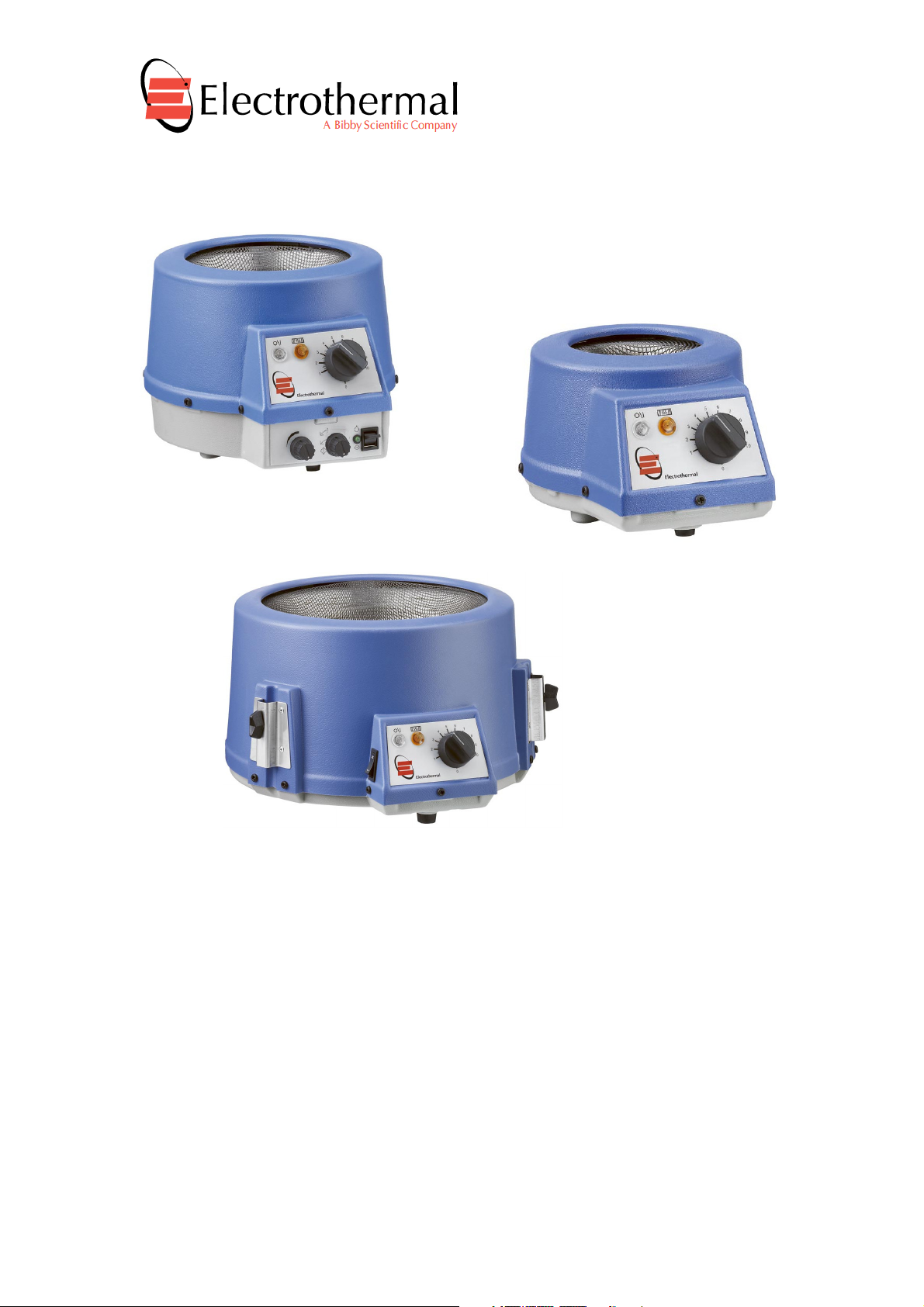
EM , SERIES ELECTROMANTLES.
INSTRUCTION BOOK
Page 1 of 28 M6873 Issue 12.7

Please take your time to read this Instruction book in order to understand the
Contents.
Section 1.
Page 3
Section 2.
Page 4
Section 3.
Page
5
Section 4.
Page
7
Section 5.
Page
9
Section 6.
Page
10
Section 7.
Page
11
Section 8.
Page
14
Section 9.
Page
19
Section 10.
Page
22
Section 11.
Page
25
Section 12.
Page 26
Section 13.
Page 28
Appendix ‘A’
Page
24
Bibby Scientific Limited.
safe and correct use of your new Bibby Scientific product.
It is recommended the Responsible Body for use of this equipment reads this
Instruction book and ensures the user(s) are suitably trained in its operation.
Introduction
Symbols and using this instructions book.
Safety Information.
Unpack and Contents.
Installation.
Environmental Protection.
Product Operation.
Technical Specification.
Maintenance
Replaceable Parts and Accessories
Customer Support
Notes
EC Declaration of Conformity.
Decontamination Certificate
© The copyright of this instruction book is the property of Bibby Scientific Limited. This instruction book is
supplied by Bibby Scientific Limited on the express understanding that it is to be used solely for the
purpose for which it is supplied. It may not be copied, used or disclosed to others in whole or part for any
purpose except as authorised in writing by Bibby Scientific Limited. Bibby Scientific Limited reserves the
right to alter, change or modify this document without prior notification.
In the interest of continued development Bibby Scientific Limited reserve the right to alter or
modify the design and /or assembly process of their products without prior notification.
This product is manufactured in Great Britian by Electrothermal, part of the Bibby Scientific Group
of companies.
Beacon Road,
Stone,
Staffordshire ST15 0SA,
Great Britain.
Tel: +44(0)1785 812121
Fax: +44(0)1785 810405
Page 2 of 28 M6873 Issue 12.7

1. INTRODUCTION.
1.1. The Bibby Scientific series of heating mantles has been specifically designed to
provide a comprehensive answer to heating fluids in round bottomed glassware in
the modern laboratory. It combines the traditional Electrothermal heating element
with many new features thus providing the user with several options to meet different
applications.
1.2. Heating control is provided by a built-in solid state energy regulator. Non stirring
mantles can be used with an external controller. (Please contact distributor /
manufacturer for details).
1.3. The enclosures of individual heating mantles EM’s are manufactured from chemical
resistant Polypropylene.
1.4. The products are provided with ventilation slots underneath and around the rim to
ensure a low enclosure surface temperature. The heating element is retained in
thermal Rockwool to create a heating cartridge that facilitates very easy replacement
in the event of any damage. On all EM sizes up to 1 litre a single support clamp is
provided at the rear of the unit. On the 2, 3 and 5 litre models there are three rod
support clamps. The EMV’s and EMX’s have a hole in the base to enable funnels or
bottom outlet flasks to be heated. All EM’s are supplied with support rods and
clamps.
1.5. Bibby Scientific offers a comprehensive range of Mantles, and Controllers. The
Mantles range from the Standard cool-to-touch vented case EM, with element
temperatures between ambient and 450 deg C. The Standard EM Mantle has
Controlled /C, Spill-Proof EMX, V-Shaped EMV, Heating and Stirring EMA with
single or bi-directional stirring options. Capacities for round-bottomed glassware
ranging from 50ml up to 5,000ml, plus funnel options. Replacement heater cartridges
are available.
Page 3 of 28 M6873 Issue 12.7
2. SYMBOLS AND USING THIS INSTRUCTION BOOK
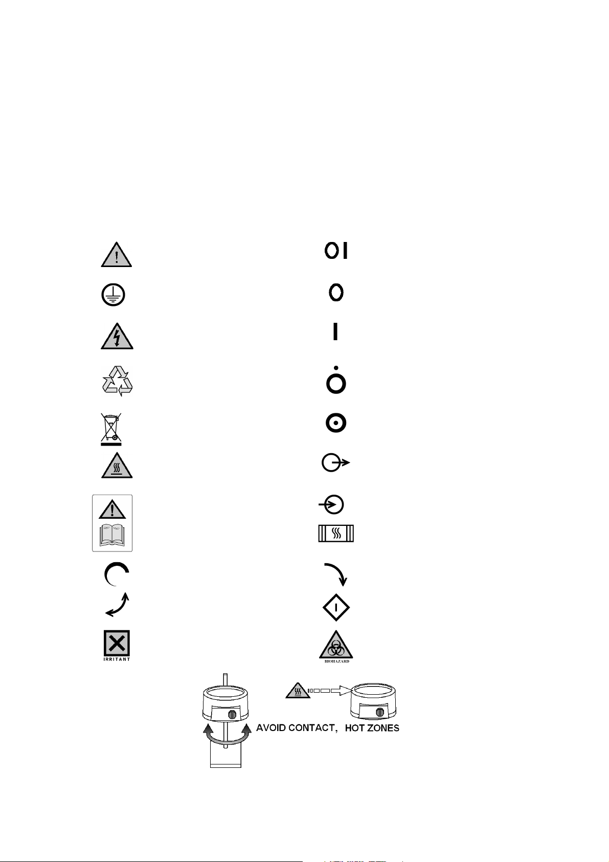
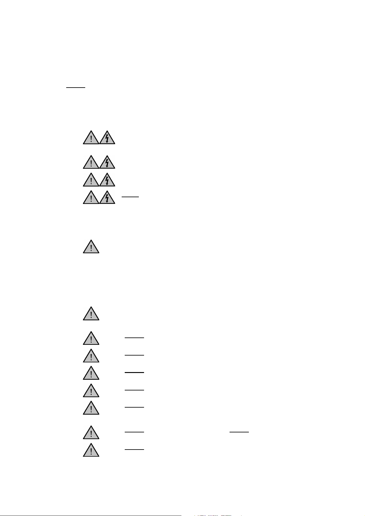
2.1. Throughout this Instruction book the following symbols are shown
to identify conditions which pose a hazard to the user, or to identify actions that
should be observed. These symbols are also shown on the product, or its
packaging. When a symbol is shown next to a paragraph or statement it is
recommended the user takes particular note of that instruction in order to prevent
damage to the equipment or to prevent injury to one’s self or other people.
The Responsible Body and the Operator should read and be familiar with this
Instruction book in order preserve the protection afforded by the equipment.
To prevent injury or equipment damage it is the manufacturers
recommendation that all persons using this equipment are suitably trained
before use.
2.2. Symbols defined.
Caution, risk of danger. See note or
adjacent symbol.
Protective conductor terminal to be
earthed.
(Do not loosen or disconnect).
Caution / risk of electric shock
Recyclable Packing Material.
Do not dispose of product in normal
domestic waste.
This symbol adjacent to an indication lamp
means mains power Off/On when lamp nonilluminated / illuminated
This symbol adjacent to a switch denotes the Off
condition for mains power.
This symbol adjacent to a switch denotes the ON
condition for mains power.
This symbol adjacent to a switch denotes the Off
condition for the Heater or Stirrer.
This symbol adjacent to a switch denotes the On
condition for a Heater or Stirrer.
Caution. Hot surface.
Refer to Instructions book.
This symbol denotes stirrer speed
control.
This symbol adjacent to the stirrer
switch denotes the bi-directional stir
condition with auto-reverse.
Material irritant to skin. When handling
wear face mask to BS/EN 149 and
protective gloves
This symbol indicates an output terminal for the
equipment.
This symbol indicates an input terminal for the
equipment.
This symbol adjacent to an indication lamp
means the heater power Off / On when lamp
non-illuminated / illuminated.
This symbol adjacent to the stirrer switch
denotes the uni-directional stir condition.
This symbol adjacent to the stirrer switch
denotes the stirrer manual capture condition or
stirrer off.
Bio Chemical Hazard. Caution required. Will
require decontamination.
Hot Zone on product
EM, EM/E, EMV,
EMX.
Page 4 of 28 M6873 Issue 12.7
DO NOT
Never
Do not
Do not
Do not
Do not
Do not
Do not
Do not
Do not
3. SAFETY INFORMATION.
This product has been designed for safe operation when used as detailed in accordance with
the Manufacturers instructions.
NOTE: Failure to use this equipment in accordance with the manufactures instruction book
may compromise your basic safety protection afforded by the equipment and may invalidate
the warranty / guarantee. The warranty / guarantee does not cover damaged caused by faulty
installation or misuse of the equipment
3.1. Prevention of Fire and Electric Shock.
To prevent a risk of fire or electric shock,
case without authorisation. Only qualified Service personnel should
attempt to repair this product.
Replace fuses only with the type as listed in section, ‘Technical
Specifications and Parts and Accessories’ (See fuse type and rating).
Ensure the Mains Power Supply conforms to rating found on the data
plate located on the back of this product.
Operate this equipment without connection to earth / ground.
Ensure the mains supply voltage is correctly earthed / grounded in
accordance with current area legislation.
3.2. General Safe Operating Practice.
Always follow good laboratory practice when using this
equipment. Give due recognition to your company’s safety and
legislative health & safety procedures and all associated legislation
applicable to your areas of operation. Check laboratory procedures for
substances being heated and ensure all hazards (e.g. explosion,
implosion or the release of toxic or flammable gases) that might arise
have been suitably addressed before proceeding. When heating
certain substances the liberation of hazardous gases may require the
use of a fume cupboard or other means of extraction.
Ensure equipment is used on a clean, dry, non-combustible, solid work
surface with at least 300mm suitable clearance all around from other
equipment.
position the product so that it is difficult to disconnect from the
mains supply.
touch the heating element or any glass vessel whilst in use.
open your product
lean or stretch over equipment, glassware and fixings when in
use.
immerse unit in water or fluids.
spill substances onto the mantle. If spillage does occur,
disconnect unit from mains supply and follow instructions as detailed
in Maintenance. (Section 9).
cover the mantle whilst in use.
block or obstruct
ventilation slots / airways.
leave equipment switched on without a charged flask(s).
Page 5 of 28 M6873 Issue 12.7

Do not
Do not
ATTENTION:
-
as the insulation used may obstruct the convection
cooling airways around the rim of the cartridge enclosure and cause
the mantle to overheat.
It is not recommended to leave any heating apparatus unattended
during operation.
Only use Original Equipment manufactures spares and accessories.
Ref Section 10.
Stirring versions of this equipment generate magnet fields. Keep all
metal objects and magnetic data devices (e.g. credit cards) away from
the stirrer unit.
The equipment is not spark, flame or explosion proof and has not been
designed for use in hazardous areas in terms of BSEN 6007914:1997. Keep flammable, low flash point substances away from the
apparatus.
Keep the Mains cord and moulded IEC plug and lead set away
from the heating surface.
thermally insulate the exposed upper section of the vessel(s),
operate or handle any part of the product with wet hands.
With high energy input and certain configurations of glassware in
EMV & EMX products, where the heating contact of the glassware is
relatively small, localised heating and subsequent ‘bumping’ of the fluid
being heated may occur. Application advice should be sought from the
manufacturer.
Page 6 of 28 M6873 Issue 12.7
‘A’
‘V’
‘X’
3 or 6 =
‘S’
‘C’
‘E’
4. UNPACKING AND CONTENTS.
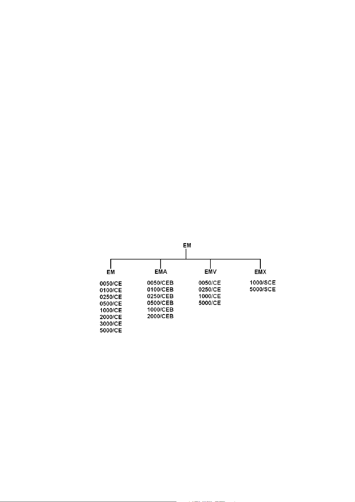
4.1. Product Identification:
A Catalogue number allocated to each type of mantle is descriptive. The method of coding is
detailed below.
First and second Characters EM Series
Next Character
Next Character (if Multi bank)
Next four Characters Flask size in ml. 0050, 0100, 0500, 1000,
Next Character after the /
Next Character
Last Characters No Characters = 230V, X1 = 115V,
The following family tree outlines product variants.
unit with stir facility.
Bottom opening for funnel.
Spillproof (Stainless Steel liner) with
bottom opening for funnel.
3 way or 6 way.
2000, 3000, 5000.
Spillproof (Stainless steel liner).
Controlled.
Earthed screen.
X7 = 220V with Chinese mains lead
Page 7 of 28 M6873 Issue 12.7
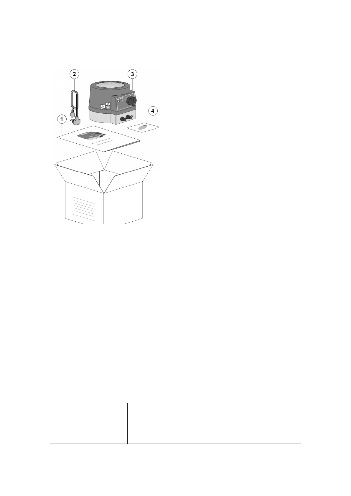
Item
Description
Qty
1
1
2
A/R
3
1
4
1
Please check the contents of your carton against the relevant product diagram.
Applicable to all EM product.
No
Instruction book
Mains cord and moulded IEC plug
and lead set
(May differ from illustration depending on
destination).
EM product (Model shown EMA)
Stir bar (only on EMA)
For future reference
please record your
products Serial and
Model Numbers.
Serial Number Unit Model/Cat Number
Page 8 of 28 M6873 Issue 12.7
Blue
or
White
=
Neutral
Brown
or
Black
=
Live / line
hot.
5. INSTALLATION.
5.1. Electrical safety and installation.
5.1.1. This equipment is designed to be used safely under the following conditions:-
• Indoor use.
• Altitude up to 2000 meters.
• Temperatures between 5°C and 40°C.
• Maximum relative humidity 80% for temperatures up to 31°C decreasing linearly
to 50% relative humidity at 40°C.
• Mains supply voltage fluctuations up to ± 10% of the nominal voltage.
• Transient overvoltages typically present on the mains supply. Overvoltage
category II
• Applicable rated pollution degree 2.
5.1.2. This equipment must be earthed / grounded to a fixed earth / grounded
mains socket outlet. The mains supply is to earthed / grounded in accordance with
current legislation. See Technical Specification for recommended fuse ratings.
5.1.3. Ensure only the correct rated mains input fuses are fitted. (Where applicable
ensure the correct Mains cord and moulded IEC plug and lead set fuse if fitted).
See Technical Information Section 8 of this Instructions book.
5.1.4. Check the voltage on the product data label on this product unit and those of any
accompanying electrical accessory. Ensure the rating conforms to your local
supply.
5.1.5. This product should be connected to a mains supply source which incorporates a
RCD or GFCI device that has a tripping current of 30mA or less. The RCD or GFCI
residual Current Device cuts off power to the equipment immediately it detects a
current leakage fault. For example, cutting off the power when there is an
accidental liquid spillage in a mantle protected with an earth (ground) screen.
5.1.6. Do not install this product or accessories on a surface which may
become flooded.
5.1.7. The unit is supplied with a Mains cord and moulded IEC plug and lead set wired
as follows.
Green / Yellow
5.2. Observation: the surface of the heating element of a mantle cartridge will upon receipt
look slightly discoloured. This discolouration is normal and occurs at the factory during
test when the mantle is first heated up.
5.3. Bibby Scientific controllers, series MC227 / MC228 / MC242 / MC5 and MC810B, can
also be used for external control when the mantle is used in a fume cupboard. NOTE:
External controllers cannot be used for EMA or EMEA products.
Page 9 of 28 M6873 Issue 12.7
or
Green = Earth / Ground

USA Notification.
Warning ! Any modification or changes made to this device, unless explicitly approved by Bibby Scientific,
will invalidate the authorisation of this device. Operation of an unauthorised device is prohibited under
Section 302 of the Communications Act of 1934 as amended, and Subpart 1 of Part 2 of Chapter47 of the
code of Federal Regulations.
Note: This equipment has been tested and found to comply with the limits for a Class B digital device,
pursuant to part 15 of the FCC Rules. These limits are designed to provide reasonable protection against
harmful interference in a residential installation. This equipment generates, uses and can radiate radio
frequency energy and, if not installed and used in accordance with the instructions, may cause harmful
interference to radio communications. However, there is no guarantee that interference will not occur in a
particular installation. If this equipment does cause harmful interference to radio or television reception,
which can be determined by turning the equipment off and on, the user is encouraged to try to correct the
interference by one or more of the following measures:
•
Reorient or relocate the receiving antenna.
•
Increase the separation between the equipment and receiver.
•
Connect the equipment into an outlet on a circuit different from that to which the receiver is
connected.
•
Consult the dealer or an experienced radio/TV technician for help.
6. ENVIRONMENTAL PROTECTION.
6.1. Maximum consideration has been given to environmental issues within the design and
manufacturing process without compromising end product performance and value.
6.2. Packaging materials have been selected such that they may be sorted for
recycling.
6.3. At the end of your product and accessories life, it must not be discarded as
domestic waste. Ref: EU Directive 2002/96/EC on Waste Electrical and Electronic
Equipment Directive (WEEE). Please contact your distributor / supplier for further
information. For end users outside of the EU consult applicable regulations.
6.4. This product should only be dismantled for recycling by an authorised recycling
company.
This product and accessories must be accompanied by a completed
Decontamination Certificate prior to any disposal. Copies of the Certificate are
available from your distributor of Bibby Scientific products, or you may copy and
enlarge from ‘Appendix A’ of this instruction book.
Bibby Scientific’s Electrothermal branded product range is registered with the Environment Agency under the name of as
Electrothermal Engineering Limited as being a producer of WEEE (Waste Electronic and Electrical Equipment) through b2b
Compliance, an authorised waste collection compliance scheme.
Page 10 of 28 M6873 Issue 12.7

Item
Description.
1
6
2
7
3
8
4
9
5
7. PRODUCT OPERATION.
7.1. EM, EMV and EMX Mantle with controller.
7.1.1. Overview of EM Mantle with controller.
Note: Circuit selection switch (only for
mantles with two heating circuits).
Position I is for lower heating circuits only.
Position II is for both circuits on.
Note: If an external controller is to be used, always set the energy regulator control knob
to maximum setting 10.
Mains power on indicator
Heating element on
Energy regulator control
knob
Circuit selection switch (for mantles with two
heating circuits
Data Plate
Mains input IEC socket (Contains protective
fuses).
Support rod bracket. (Note for 2, 3 & 5 litre
Heating Element
Warning Labels.
variants 3 clamp positions are fitted).
(Hot surface and refer to
this Instructions book).
Note: The EMV and EMX series
mantles both have bottom
opening for use with a funnel.
EMX has a spill proof liner. Both
units may be raised up using a
retort rod stand allowing for
heated filtration of the sample.
Both mantles can be supported
using the rod clamp arrangement
as illustrated.
Page 11 of 28 M6873 Issue 12.7

7.1.2. When heating a funnel in an EMV or EMX the mantle should be
Item
Description.
1
2
3
4
5
6
8
9
10
11
12
securely supported above the work surface using the support rod clamps.
7.1.3. With the mains electricity supply switched off, connect the Mains cord and
moulded IEC plug and lead set to the mains IEC socket.
7.1.4. Place a charged, clean, dry glass vessel of the size indicated on the mantle data
plate label. Wherever possible the glass vessel should be supported within the
mantle by means of the support rod and clamp.
7.1.5. Switch on the mains electrical supply. Adjust the controller regulator knob to the
required setting.
NOTE: The ‘mains power on’ indication neon will illuminate. The ‘amber
heating on’ neon will illuminate / pulsate when the heaters are in operation.
7.1.6. When the process is complete switch the regulator knob to the off position.
Disconnect the mains electricity supply.
7.1.7. Remove charged vessel. Handle hot charged vessel with care.
7.2. EMA Mantle (With controller and stir facility).
7.2.1. Overview of EMA Mantle with stir facility.
Mains power on indicator
Heating element on
Energy regulator control knob
Heating Element
Warning Labels.
(Hot surface and refer to this
Instructions book).
Stir speed adjustment.
Stir selection rotary switch.
Stir facility ‘on’ LED indicator.
Data Plate
Mains input IEC socket (Contains
protective fuses).
Support rod bracket. (Note for 2, 3
& 5 litre variants 3 clamp
positions are fitted).
Page 12 of 28 M6873 Issue 12.7

7.2.2. With the mains supply electricity switch off, Connect the Mains cord and moulded
IEC plug and leads set to the mains IEC socket. Ensure the stirrer rotary switch is in
the off position.
7.2.3. Place a charged, clean, dry glass vessel of the size indicated on the mantle data
plate. Wherever possible the glass vessel should be supported within the mantle by
means of the support rod and clamp.
7.2.4. Switch on the mains electrical supply. Adjust the Energy regulator control knob to
the required setting.
NOTE: The mains power on indication neon will illuminate. The amber heating
on neon will illuminated when the heaters are in operation.
7.2.5. On the EMA there are two stirring functions available.
a) Bi-directional with auto capture and auto reverse period of approximately 20 /
30 seconds.
b) Uni-directional up to 500RPM approximately.
c) Manual capture / reset is achieved with the rotary switch in the off position.
7.2.6. Carefully place the stirrer bar provided into the vessel and turn the rotational
speed control to its minimum position.
7.2.7. Select the required stir function on the stir selection rotary switch. The green LED
will now illuminate.
7.2.8. Adjust the rotational speed by means of the speed control knob. Should the
stirring action be lost by over rotation, then reduce the stir speed slightly and
recapture the stir bar by selecting the off position on the stir selection rotary switch
7.2.9. When the process is complete switch the stir speed and regulator knobs to there
off positions. Disconnect the mains electricity supply.
7.2.10.
Remove charged vessel. Handle hot charged vessel with care.
Page 13 of 28 M6873 Issue 12.7

Type
Size Total
Heating
Po
wer
Fuse rating (Amps)
EM
EMA
The power consumption of the stir facility is 20 Watts.
EMV
EMX
8. TECHNICAL SPECIFICATION.
8.1. Specifications EM range (General).
Mains cord and moulded IEC plug
and lead set cable (UK) 13A BS1362
AZ9165
Mains cord and moulded IEC plug
and lead set cable (Europe)
AZ6747
Mains cord and moulded IEC plug
and lead set cable (USA)
AZ6746
Fuse type 20mm x 5mm Glass Quickblow. (2 per unit) See below
Heating Element Construction. Thermal insulated element wire stitched into a cartridge
Maximum Element temperature.
EM Case construction. Polypropylene.
Thermal Insulation Ceramic Fibre.
8.1.1. Power Consumption and fuse ratings.
3 core earthed / ground. 2 meters long
Moulded IEC plug and Lead set – supply cord H05 V VF- Replace only with equivalent cable.
3 core earthed / ground. 2 meters long
Moulded IEC plug and Lead set – supply cord H05 V VF- Replace only with equivalent cable.
3 core earthed / ground. 2 meters long
Moulded IEC plug and Lead set – supply cord SJT VW
1- 105° Replace only with equivalent cable.
for rating.
construction.
450°C. Nominal Max.
(Watts).
220/240V∼∼∼∼ 115V∼∼∼∼ 220/240V∼∼∼∼ 115V∼∼∼∼
50ml 60 70 F0.5 F1.25
100ml 60 70 F0.5 F1.25
250ml 150 150 F1.25 F2.5
500ml 200 200 F1.25 F2.5
1000ml 300 300 F2.5 F3.15
2000ml 500 500 F2.5 F6.3
3000ml 500 500 F2.5 F6.3
5000ml 500+300 500+300 F6.3 F6.8
50ml 60+(20stir) 76+(20stir) F0.5 F1.25
100ml 60+(20stir) 76+(20stir) F0.5 F1.25
250ml 150+(20stir) 190+(20stir) F1.25 F2.5
500ml 200+(20stir) 250+(20stir) F1.25 F2.5
1000ml 300+(20stir) 380+(20stir) F2.5 F6.3
2000ml 500+(20stir) 650+(20stir) F2.5 F6.3
50ml 60 70 F0.5 F1.25
250ml 100+50 100+50 F1.25 F2.5
1000ml 200+100 200+100 F2.5 F3.15
5000ml 500+300 500+300 F6.3 F8
1000ml 165+80 160+80 F1.25 F2.5
5000ml 400+200 400+200 F6.3 F10
8.1.2. The Ingress protection rating for the EM, EME, EMV and EMA product range is IPX0.
For the EMX range the Ingress protection rating is IPX1.
8.1.3. Dimensions and Weight (unpacked).
Page 14 of 28 M6873 Issue 12.7

EM 50ml
EM 100ml
EM 250ml
EM1000
WEIGHT 0.78Kg
WEIGHT 0.78Kg
EM 500ml
WEIGHT 0.78Kg
WEIGHT 1.25Kg
Page 15 of 28 M6873 Issue 12.7

EM2000
EM3000
EM5000
EMV
0050/CE
. Glass sizes 10
– 50ml.
WEIGHT 1.25Kg
WEIGHT 2.58Kg
WEIGHT 2.58Kg
WEIGHT 2.58Kg
Page 16 of 28 M6873 Issue 12.7

WEIGHT 0.78Kg.
EMV0250/CE
. Glass size 100
– 250ml.
EMV1000/CE
. G
lass size 500
– 1000ml
EMV5000/CE
. Glass size 2000
– 5000ml.
WEIGHT 0.78Kg.
EMX1000/SCE Glass size 50 to 1000ml
WEIGHT 2.76Kg
EMX5000/SCE Glass size 500 to 5000ml
WEIGHT 5.69Kg
Page 17 of 28 M6873 Issue 12.7

EM
A050
/CEB
EMA
0250/CE
B
EMA0500/CE
B
EMA1000/CE
B
WEIGHT 1.73Kg
EMA2000/CEB
WEIGHT 1.73Kg.
WEIGHT 2.75Kg.
WEIGHT 2.75Kg
WEIGHT 5.68Kg
Page 18 of 28 M6873 Issue 12.7

9. MAINTENANCE.
9.1. General Information.
Unplug the unit from the mains voltage supply and allow it to cool before
undertaking any maintenance tasks.
Maintenance should only be carried out under the direction of the Responsible
Body, by a competent electrician. Failure to do so may result in damage to the product
and in extreme cases be a danger to the end user.
With proper care in operation this equipment has been designed to give many years of
reliable service. Contamination or general misuse will reduce the effective life of this
product and may cause a hazard.
Maintenance for the unit should include:
• Periodic electrical safety testing (an annual test is recommended as the minimum
requirement).
• Regular inspection for damage with particular attention to the mains lead and
plug set.
• Routine cleaning of the equipment should be undertaken using a clean cloth.
DO NOT USE SOLVENTS FOR CLEANING ANY PART OF THIS
EQUIPMENT.
9.2. Fuse Replacement.
The mains fuse holder is located at rear your product. Refer to Technical specification,
‘Fuse Rating’ for correct fuse type and rating. Turn your product off and disconnect it from
the mains supply.
9.2.1. Heater Cartridge replacement.
Page 19 of 28 M6873 Issue 12.7
Attention. The heater contains insulation material made from
Refractory Ceramic Fibres (RCF), classified as a category 2 carcinogenic
under EU Directive 67/548/EC. Follow the guidelines for working with RCF
as laid down under in the ECFIA Code of Practise. Wear suitable protective
clothing and gloves.

EM and EMA
9.2.1.1. Unplug or disconnect the mantle from the mains electricity supply.
9.2.1.2. The EM single heater mantles should be turned over and placed upside
9.2.1.3. Remove the plastic rivets from around the base of the mantle and remove
9.2.1.4. On 2,3 and 5 litre models remove the 3 cross-head screws and remove the
9.2.1.5. On EM product remove the 2 cross-head screws retaining the base bracket
9.2.1.6. Disconnect the two or four heater cold leads. (The number of leads is
9.2.1.7. Lift the heater cartridge out of the case without disconnecting the earth
9.2.1.8. The new heater cartridge is then fitted into the metal ring and the heater cold
9.2.1.9. On EM product replace the base bracket. On the 2,3, and 5 litre model EM’s
9.2.1.10. Replace the earth lead and base and refasten using the previously
9.2.1.11. The responsible body shall check the electrical safety of the product
In the event of a heater element becoming damaged or open circuit the
follow procedure should be adopted for its replacement.
down on a clean dry surface.
the base.
triangular base plate.
then hinge the bracket clear of the heater cartridge.
dependant on single / double element configuration).
connection to the metal ring.
leads reconnected.
replace the triangular base plate and refit the 3 screws.
removed plastic rivets.
before further use.
Page 20 of 28 M6873 Issue 12.7

9.3. Spillage and Decontamination.
Spillage:
In the event of spillage or glassware fracture, do not touch the mantle. Disconnect
the product from the mains electrical supply. Allow the product to cool. Wearing
suitable hand protection (giving due consideration to substances that were being
heated) carefully remove any pieces of broken glassware. If decontamination is
necessary, see section below. Otherwise wipe off all excess liquid from the mantle
and surrounding area using an absorbent soft cloth. Drain of any residual fluid
retained in the mantle. In the case of excessive spillage/ flask fracture, invert the
mantle and allow it to drain for minimum of one hour. Then proceed with the
following drying out procedure. Place the complete mantle, the correct way up, in a
heated oven at 50 °C for a minimum period of 40 hours
! Warning: The equipment cannot be assumed to meet all the safety requirements
of EN 61010-2-010: 2003 during the drying out process and until the drying out
process is completed.
If in doubt please consult Customer Support. Refer to section 11.” NB:
Replacement heater cartridges are obtainable from your Distributor/Manufacturer.
Before further use, the mantle must be subjected to electrical safety
testing by competent service personnel.
If in doubt please consult Customer Support. Refer to section 11.
If the equipment has been exposed to contamination, the Responsible
Body is responsible for carrying out appropriate decontamination. If hazardous
material has been spilt on or inside the equipment, decontamination should only
be undertaken under the control of the Responsible Body with due recognition of
possible hazards. Before using any cleaning or decontamination method, the
Responsible Body should check with the manufacturer the proposed method will
not damage the equipment.
Prior to further use, the Responsible Body shall check the electrical safety of the
unit. Only if all safety requirements are met can the unit be used again. The above
procedure is intended as a guide. Should spillage occur with a toxic or hazardous
fluid then special precautions may be necessary.
Decontamination Certificate.
Note: In the event of this equipment or any part of the unit becoming damaged, or
requiring service, the item(s) should be returned to the manufacturer for repair
accompanied by a decontamination certificate. Copies of the Certificate are available
from Distributor/Manufacturer. Appendix A of this instructions book may be
copied and enlarged.
At the end of life, this product must be accompanied by a Decontamination
Certificate. See section 6.3 and 6.4
Page 21 of 28 M6873 Issue 12.7

Mantle model type
Replacement heater Cartridge.
10. PARTS AND ACCESSORIES
10.1. Replacement Heater Cartridges. All Bibby Scienetific mantles are specified by
the letters RE and Flask size. Add x1 suffix when ordering for 115V
For all 220/240 volt product quote the Non x1 part number.
EM0050/CE, Order RE0050
EM0100/CE Order RE0100
EM0250/CE Order RE0250
EM0500/CE Order RE0500
EM1000/CE Order RE1000
EM2000/CE Order RE2000
EM3000/CE Oder RE3000
EM5000/CE Order RE5000
EMA0050/CE, EMA0050/CEB. Order REA0050
EMA0100/CE, EMA0100/CEB. Order REA0100
EMA0250/CE, EMA0250/CEB. Order REA0250
EMA0500/CE, EMA0500/CEB. Order REA0500
EMA1000/CE, EMA1000/CEB. Order REA1000
EMA2000/CE, EMA2000/CEB. Order REA2000
EMX1000/SCE Order REMX1000
EMX5000/SCE Order REMX5000
EMV0050/CE Order REMV0050
EMV0250/CE Order REMV0250
EMV1000/CE Order REMV1000
EMV5000/CE Order REMV5000
Page 22 of 28 M6873 Issue 12.7

Order Number
Description.
Quantity
AZ
9165
1
AZ
129409
1
AZ6746
1
AZ6747
1
AZ9021
1
AZ9034
10
AZ9035
10
AZ9036
10
AZ9038
10
AZ9040
10
AZ9041
10
AZ9130
10
CR
M5607
1
CR
M5608
1
CR
M5619
1
CR
M5620
1
CR
M5621
1
129320/3
1
129320/4
1
129320/5
1
129320/6
1
10.2. REPLACEABLE PARTS.
Mains cord and moulded IEC plug and lead set (UK) 230V-AC
Mains cord and moulded IEC plug and lead set (USA) 115V-AC
Mains cord and moulded IEC plug and lead set (USA) 115V-AC
Mains cord and moulded IEC plug and lead set (Europe) 230V-AC
Spares Pack Simmerstat Controller
Fuse: F10A
Fuse: F8A
Fuse: F6.3A
Fuse: F0.5A
Fuse:F2.5A
Fuse: F3.15A
Fuse; F3A
Neon: Clear (230V)
Neon: Amber (230V)
Neon: Clear (115V)
Neon: Amber (115V)
Switch, Element Selection (EMX, EMV).
Support rod (710mm / 28 “ long).
Support rod (1160mm / 45” long).
Support rod (1440mm / 55” long).
Support rod (590mm / 23” long).
APPENDIX ‘A’. DECONTAMINATION CERTIFICATE.
Page 23 of 28 M6873 Issue 12.7

.
Bibby Scientific Limited
Beacon Road, Stone, Staffordshire ST15 0SA. Great Britain
Tel: +44(0)1785 812121. Fax: +44(0)1785 810405
E-mail:
electrothermalhelp@bibby-scientific.com
DECONTAMINATION CLEARANCE CERTIFICATE
For the Inspection, Repair or Return of Medical, Laboratory or Industrial Equipment.
Prior to a Service Engineer working on equipment that has been in an environment where substances hazardous to health may have been
used, you are requested to provide the following information:
CUSTOMER DETAILS
Company:-
Department:-
Contact Name:-
Tel No:-
Fax No:-
Address:-
Post Code:-
Product Description
Model No:-
Has the equipment been exposed to any of the following, Please answer all questions by deleting YES/NO as applicable and by providing
A. Blood, body fluids, Pathological
specimens
B. Biodegradable material that could
become a hazard
C. Other biohazard YES/NO Provide details if YES
D. Chemical or substances hazardous to
health
E. Radioactive substances State name(s)
and quantities of isotopes and checks
made for residual activity
F. Other hazards YES/NO Provide details if YES
2. Please provide details of any hazard present as indicated above. Include details of names and quantities of
agents as appropriate:-
3. Your method of decontamination (please describe):-
4. Are there likely to be any areas of residual contamination (please specify)
I declare that the above information is true and complete to the best of my knowledge and belief.
Authorised signature:- Name (please print):-
Title/Position:-
For and behalf of:- Date:-
details in section 2 below.
YES/NO Provide details if YES
YES/NO Provide details if YES
YES/NO Provide details if YES
YES/NO Provide details if YES
Serial No:-
11. CUSTOMER SUPPORT.
Page 24 of 28 M6873 Issue 12.7

Bibby Scientific Limited.
For the America’s and Canada, contact:
For help and support in using this product, please contact Electrothermal at the following
address.
Beacon Road,
Stone,
Staffordshire ST15 0SA,
Great Britain.
Tel: +44(0)1785 812121
Fax: +44(0)1785 810405
• General enquiries :
info@bibby-scientific.com
• Order enquiries :
sales@bibby-scientific.com
• Technical support :
electrothermalhelp@bibbyscientific.com
• www.electrothermal.com
12. NOTES
Techne Incorporated, 3 Terri Lane,
Suite 10 Burlington, NJ 08016 USA.
Toll free:800-225-9243Tel: 609-589-2560
Fax: 609-589-2571
Email: labproducts@techneusa.com
Http www.techneusa.com
Page 25 of 28 M6873 Issue 12.7

Page 26 of 28 M6873 Issue 12.7

13. EC DECLARATION OF CONFORMITY.
Page 27 of 28 M6873 Issue 12.7

Bibby Scientific Limited.
For the America’s and
Canada, contact:
Distributors Stamp
CE marked products and associated accessories covered by this Instruction book conform to the
essential requirements of the following directives:
EMC Directive.
Low Voltage Directive.
A full copy of the EC Declaration / Conformity document can be obtained from the manufacture at
the email address : info@bibby-scientific.com
Beacon Road,
Stone,
Staffordshire ST15 0SA,
Great Britain.
Tel: +44(0)1785 812121
Fax: +44(0)1785 810405
• General enquiries :
info@bibby-scientific.com
• Order enquiries :
sales@bibby-scientific.com
• Technical support :
electrothermalhelp@bibbyscientific.com
• www.electrothermal.com
Part of the Bibby Scientific Group
Techne Incorporated, 3 Terri Lane,
Suite 10 Burlington, NJ 08016 USA.
Toll free:800-225-9243Tel: 609-589-2560
Fax: 609-589-2571
Email: labproducts@techneusa.com
Http www.techneusa.com
Page 28 of 28 M6873 Issue 12.7
2013 Bibby Scientific Limited. All rights reserved.
 Loading...