


Volts / Amps |
S0224921 |
|
|
(Primary Instruments) |
|
(VA-1A, VA-1A-XX & RSVA-3) |
|
Operating and Installation Instructions
OI 041032 and II 040934
4/9/83 Rev. C: 2/24/92 **
Now Works in All Shunt Locations and comes with External Warning Control Line!
S/N: ~74000 and up.
You must read this manual before installing or operating the instrument. This manual contains warranty and other information that may affect your decision to install this product and/or the safety of your aircraft.
Model:
S/N:
 Electronics International Inc. ®
63296 Powell Butte Hwy • Bend, OR 97701 • (541) 318-6060 • Buy-EI.com

Important Notice
***** MUST READ *****
If you think it is not important to read this manual, you're wrong! This manual contains important installation information that may affect the safety of your aircraft, delay your installation or affect the operation of your instrument. You Must read this manual prior to installing your instrument. Any deviation from these installation instructions is the sole responsibility of the installer/pilot and may render the STC invalid.
Read the Warranty / Agreement. There is information in the Warranty / Agreement that may alter your decision to install this product. If you do not accept the terms of the Warranty / Agreement, do not install this product. This product may be returned for a refund. Contact Electronics International inc. for details.
Check that the instrument make and model marked on the side of the instrument and on the invoice are correct before starting the installation. The VA-1A is an internal shunt unit and the VA-1A-XX is an external shunt unit (“XX” = your aircraft shunt value in amps).
It is possible for any instrument to fail thereby displaying inaccurate high, low or jumpy readings. Therefore, you must be able to recognize an instrument failure and you must be proficient in operating your aircraft safely in spite of an instrument failure. If you do not have this knowledge, contact the FAA or a local flight instructor for training.
The ability for this product to detect a problem is directly related to the pilots interpretation and observation skills.
The pilot must understand the operation of this product before flying the aircraft. Do not allow anyone to operate the aircraft that does not know the operation of this product. Keep the Operating Manual in the aircraft at all times.
|
Contents |
|
WARRANTY ................................................................................................................... |
2 |
|
VA-1A, VA-1A-XX Operating Instructions .................................................................... |
3 |
|
Features ........................................................................................................................................................... |
3 |
|
VA-1A Installed in the Battery Lead .............................................................................................................. |
4 |
|
VA-1A Installed in the Alternator Lead .......................................................................................................... |
6 |
|
VA-1A, VA-1A-XX Installation Instructions .................................................................. |
8 |
|
General Information ........................................................................................................................................ |
8 |
|
Installation ....................................................................................................................................................... |
9 |
|
1. |
Important Information and Initial Check Out: ........................................................................................ |
9 |
2. |
Instrument Set Up: .................................................................................................................................. |
9 |
3. |
Determine how the VA Unit will be installed in your aircraft's electrical system: ................................. |
9 |
4. |
Install the External Shunt (External Shunt Unit Only, VA-1A-XX): ................................................... |
12 |
5. |
Route the Circular Connectors: ............................................................................................................. |
12 |
6. |
Route the Power and Ground Wires: .................................................................................................... |
12 |
7. |
Route the Backlight Wires: ................................................................................................................... |
12 |
8. |
Route the Shunt Wires (External Shunt Unit Only, VA-1A-XX): ........................................................ |
13 |
9. |
Connect the Large Shunt Wires (Internal Shunt Unit Only, VA-1A): .................................................. |
13 |
10. |
Install the Instrument in the Panel: ....................................................................................................... |
13 |
11. |
Connect the Circular Connector to the Instrument: ............................................................................. |
13 |
12. Ground Test: ........................................................................................................................................ |
13 |
|
Troubleshooting .............................................................................................................. |
14 |
|
VA-1A (Internal Shunt Unit) Wiring Diagram .............................................................. |
16 |
|
VA-1A-XX (External Shunt Unit) Wiring Diagram ...................................................... |
17 |
|
VA-1A and VA-1A-XX Circular Connector ................................................................. |
18 |
|
RSVA-3 Installation Instructions ................................................................................... |
19 |
|
1. Install the External Shunt: ........................................................................................................................ |
19 |
|
2. Install the VA-1A-XX Instrument: .......................................................................................................... |
19 |
|
3. Route the Shunt Wires: ............................................................................................................................ |
19 |
|
4. Route the Instrument Wires to the RSVA-3: ........................................................................................... |
19 |
|
5. Install the RSVA-3 in the Panel: .............................................................................................................. |
20 |
|
6. Ground Test: ............................................................................................................................................ |
20 |
|
RSVA-3 Wiring Diagram ............................................................................................... |
22 |
|
Specifications and Operating Features ........................................................................... |
23 |
|
STC Information........................................................................................ |
See Back Pages |
|
1
Warranty / Agreement
Electronics International Inc. warrants this instrument and system components to be free from defects in materials and workmanship for a period of one year from the user invoice date. Electronics International Inc. will repair or replace any item under the terms of this Warranty provided the item is returned to the factory prepaid.
1.This Warranty shall not apply to any product that has been repaired or altered by any person other than Electronics International Inc., or that has been subjected to misuse, accident, incorrect wiring, negligence, improper or unprofessional assembly or improper installation by any person. This warranty does not cover any reimbursement for any person’s time for installation, removal, assembly or repair.
Electronics International retains the right to determine the reason or cause for warranty repair.
2.This warranty does not extend to any machine, vehicle, boat, aircraft or any other device to which the Electronics International Inc. product may be connected, attached, interconnected or used in conjunction with in any way.
3.The obligation assumed by Electronics International Inc. under this warranty is limited to repair, replacement or refund of the product, at the sole discretion of Electronics International Inc.
4.Electronics International Inc. is not liable for expenses incurred by the customer or installer due to factory updates, modifications, improvements, upgrades, changes, or any other alterations to the product that may affect the form, fit, function or operation of the product.
5.Personal injury or property damage do to misinterpretation or lack of understanding this product is solely the pilots responsibility. The pilot must understand the operation of this product before flying the aircraft. Do not allow anyone to operate the aircraft that does not know the operation of this product. Keep the Operating Manual in the aircraft at all times.
6.E. I. Inc. is not responsible for shipping charges or damages incurred under this Warranty.
7.No representative is authorized to assume any other liability for Electronics International Inc. in connection with the sale of Electronics International Inc. products.
8.If you do not agree to and accept the terms of this warranty, you may return the product for a refund.
This Warranty is made only to the original user. THIS WARRANTY IS IN LIEU OF ALL OTHER
WARRANTIES OR OBLIGATIONS: EXPRESS OR IMPLIED. MANUFACTURER EXPRESSLY DISCLAIMS ALL IMPLIED WARRANTIES OF MERCHANTABILITY OR FITNESS FOR A PARTICULAR PURPOSE. PURCHASER AGREES THAT IN NO EVENT SHALL MANUFACTURER BE LIABLE FOR SPECIAL, INCIDENTAL OR CONSEQUENTIAL DAMAGES, INCLUDING LOST PROFITS OR LOSS OF USE OR OTHER ECONOMIC LOSS. EXCEPT AS EXPRESSLY PROVIDED HEREIN, MANUFACTURER DISCLAIMS ALL OTHER LIABILITY TO PURCHASER OR ANY OTHER PERSON IN CONNECTION WITH THE USE OR PERFORMANCE OF MANUFACTURER’S PRODUCTS, INCLUDING SPECIFICALLY LIABILITY IN TORT.
2
VA-1A, VA-1A-XX |
0219922 |
|
|
Operating Instructions |
|
OI 041032 |
|
|
Rev: C 7/13/92 |
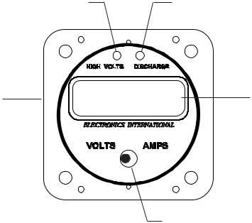
Features
1. 12/24 Volt Select Switch:
On the back of the VA-1A is a select switch to set the “High Volts” and “Discharge” warning features for a 12 or 24 volt system (see Installation Instructions).
2. “High Volts” Warning Light:
If the bus voltage rises to 15.3 volts (30.6 volts for a 24-volt system) or higher, a bright red “High Volts” warning light will alert you of this condition. The high volts feature is sensed off the red power lead and will function regardless of installation variations or what position the mode switch is in. If this light is on, an External Warning Line will be pulled low which can be used to activate an External Warning Light.
3. “Discharge” Warning Light:
If the bus voltage drops below 12.6 volts, (25.2 volts for a 24-volt system) a bright yellow “Discharge” warning light will alert you of this condition. The discharge warning feature is sensed off the red power lead and will function regardless of installation variations or what position the mode switch is in. If this light is on, an External Warning Line will be pulled low which can be used to activate an External Warning Light.
High Volts Warning Light |
|
|
|
|
|
|
|
|
|
|
|
|
|
|
|
|
|
|
|
|
Discharge Warning Light |
||
|
|
|
|
|
|
|
|
|
|
|
|
|
|
|
|
|
|
|
|
|
|
|
|
12/24 Volt Select |
12.3 |
v |
|
|
Switch (on back) |
Digital Display |
|||
|
||||
|
|
Mode Switch
3
Operating Instructions |
Features |
|
|
|
|
4. Digital Display: |
|
The VA-1A comes with 12 and 24 volt digital display back light control lines. The digital display should be backlit all the time. This will allow it to be viewed easily in dim light. The digital display is best viewed in high ambient light or direct sunlight.
Voltage will be displayed in .1 volt increments and a “V” annunciator will show in the display. Amperage will be displayed in .1 amp increments for the VA-1A and any external shunted unit 60 amps and below (i.e., VA-1A-60 and below). For any external shunted unit above 60 amps (VA-1A-70 and above) amperage will be displayed in 1 amp increments. Any time the Mode Switch is in the “Amps” position, an “A” annunciator will show in the display.
Note: When the VA-1A(-XX) is mounted in the alternator lead and the engine is off, the VA-1A(-XX) may display up to +/- .3 amps. This is due to any leakage current in the alternator and any offset in the VA-1A(- XX).
5. Mode Switch:
The Mode Switch sets the display between “Volts” and “Amps.” The setting of this switch will not affect the operation of the “High Volts” or “Discharge” warning lights.
VA-1A Installed in the Battery Lead
The two common methods of installing the VA-1A or VA-1A-XX in the electrical system of your aircraft are in the battery lead and in the alternator lead. Following are the operating characteristics of the VA-1A installed in the battery lead.
1. Master On, Engine Off:
The following describes the operating characteristics of the VA-1A installed in the battery lead with the master switch on and the engine off.
With the Mode Switch in the “Amps” position, the VA-1A will display the electrical system load on the aircraft. Since the engine is off, all of the current is being supplied by the battery. The VA-1A will show a discharging condition (the “Discharge” light will be on) and display an accurate reading of the total current drain from the battery. With all your electrical equipment off, this will be around 2 to 6 amps. In this mode of operation any piece of electrical equipment can be checked for proper operation by performing the following steps:
A. Note the amps reading on the VA unit.
4
Operating Instructions |
VA-1A Installed in the Battery Lead |
|
|
|
|
B.Turn on the piece of electrical equipment you wish to check.
C.If this piece of electrical equipment is working properly, you will see an increase in load current that corresponds to the current that piece of equipment requires. Compare this current with the current you measured for that same piece of equipment at an earlier date.
Using this method with the digital display of the VA-1A, many important aircraft functions (strobes, retracts, radios, transponder, ADFs, DMEs, pitot heat, etc.) can be checked from the pilot’s seat. It would be worthwhile to write down the load current for the entire system and for each piece of equipment. This would give you something to compare to when you wish to check for proper operation at a later date. You may also check the entire electrical system with one check by turning all the electrical equipment on and comparing the amps reading with your normal reading taken at an earlier date. If an improper reading is noted, the VA1A may then be used to diagnose which piece of equipment has malfunctioned by checking each piece of equipment separately.
With the mode select switch in the “Volts” position, the VA-1A will display the bus voltage to .1 volts. With all electrical equipment off and a fully charged battery the bus voltage will be around 12.1 to 12.5 volts (double these levels for a 24-volt system). Each battery has its own operating voltage when charged. As the battery gets near the end of its life, this voltage will start to drop. A discharged battery will also run at a lower voltage. Don’t confuse a good discharged battery with an old battery.
2. Master On, Engine On:
The following describes the operating characteristics of the VA-1A installed in the battery lead with the master switch on and the engine on.
With the Mode Switch in the “Amps” position, the VA-1A will display the charging current to the battery. When the engine is first started, the current will jump up to 20 amps or more and will quickly decrease as the battery takes a charge. Within a few minutes, the charging current will have dropped to 6 amps or lower and will continue to drop for the next hour until it settles to 1.0 amps or lower.
With the VA-1A installed in the battery lead, load current cannot be monitored during flight. The Alternator (or generator) is supplying all of the electrical load and charging the battery. Only the battery charging current can be monitored for this installation.
With the mode selector switch in the “Volts” position the VA-1A will display the bus voltage to .1 volts. With the engine running the alternator is capable of raising the bus voltage to a dangerously high level. It is the voltage regulator's job to limit the bus voltage between 13.5 and 14.8 volts (double these levels for a 24volt system). Look for this level on the VA-1A. A low voltage reading will cause the battery to charge very slowly. A high reading can damage the battery and most of your electrical equipment. If the aircraft bus voltage goes to a dangerously high level (15.3 volts or higher) a bright red “High Volts” light on the VA-1A will warn you of this condition. If this happens turn the field to the alternator off to eliminate the over voltage condition.
5
Operating Instructions |
VA-1A Installed in the Battery Lead |
|
|
|
|
Another common electrical problem is a discharging condition. If this condition goes unnoticed (which it normally does) you will end up with a dead battery in flight rendering all of your electrical equipment useless. To help you avoid this situation the VA-1A has a “Discharge” Warning Light which acts as an early warning, alerting you as soon as the battery goes into a discharging condition. The amount of discharging current can be displayed in the “Amps” position. Discharging current will be displayed as a minus number. If this situation occurs, turn off any unnecessary electrical equipment. The lower you can get the discharging current, the longer the battery will last.
The VA-1A will display trend information when your battery is in a discharging condition. As you watch the battery discharging .1 volts at a time, it becomes relatively easy to judge the remaining time you have before the battery reaches a seriously low condition. As the battery voltage approaches 11 volts (22 volts for a 24 volt system), the aircraft’s electrical equipment will start to malfunction. The exact voltage at which each piece of equipment will start to malfunction depends on the design of that equipment. The VA-1A will work accurately from 40 to 7 volts--far below where most electrical equipment starts to fail.
VA-1A Installed in the Alternator Lead
Two common methods of installing the VA-1A or VA-1A-XX in the electrical system of your aircraft are in the battery lead and in the alternator lead. Following are the operating characteristics of the VA-1A installed in the alternator lead.
1. Master On, Engine Off:
The following describes the operating characteristics of the VA-1A installed in the alternator lead with the master switch on and the engine off.
With the Mode Switch in the “Amps” position the VA-1A will display 000 (+/- a few counts). Since the battery is supplying all of the electrical load and the alternator is off (not turning), there is no current being supplied from the alternator and the “Discharge” warning light will be on.
With the mode select switch in the “Volts” position, the VA-1A will display the bus voltage to .1 volts. With all electrical equipment off and a fully charged battery the bus voltage will be around 12.1 to 12.5 volts (double these levels for a 24-volt system). Each battery has its own operating voltage when charged. As the battery gets near the end of its life, this voltage will start to drop. A discharged battery will also run at a lower voltage. Don’t confuse a good discharged battery with an old battery.
2. Master On, Engine On:
The following describes the operating characteristics of the VA-1A installed in the alternator lead with the master switch on and the engine on.
6
 Loading...