


Fuel Flow / Pressure
(FP-5 and FP-5L)
Operating Instructions
OI 0505931
5/5/93 Rev. H: 2/17/05
You must read this manual before installing or operating the instrument. This manual contains warranty and other information that may affect your decision to install this product and/or the safety of your aircraft.


 Electronics International Inc.®
63296 Powell Butte Hwy • Bend, OR 97701 • (541) 318-6060 • www.Buy-EI.com

FP-5 and FP-5L
Important Notice
********** Must Read **********
If you think it is not important to read this manual, you're wrong! This manual contains important information that may affect the safety of your aircraft.
Read the Warranty / Agreement. There is information in the Warranty / Agreement that may alter your decision to install this product. If you do not accept the terms of the Warranty / Agreement, do not install this product. This product may be returned for a refund. Contact Electronics International inc. for details.
The fuel remaining displayed by the FP-5 is not a measurement of the fuel in the tanks. It is an amount calculated from the starting fuel level you programmed into the FP-5, minus the fuel used while the engine was running. When properly calibrated, the FP-5 can accurately measure the fuel used. It is imperative the pilot verify the calibration of the FP-5 over many tanks of fuel before using the "REM" and/or "USED" Modes as an indication of the fuel in the tanks or fuel used. Even after verifying the calibration of the FP-5 it should never be used as the primary indicator of fuel quantity in the tanks. It is important the pilot visually check/measure the fuel quantity for each tank before takeoff and cross-check these readings against the Fuel Level Gauges and the FP-5. The FP-5 reminds you to do this by blinking the “REM” LED and displaying the current fuel remaining in the tanks each time the aircraft power is turned on. Also, it is important the pilot use preflight and flight planning techniques, in accordance with the FAR's, which will help insure the proper amount of fuel for the intended flight is on board the aircraft before takeoff.
While in flight the FP-5 readings should only be used to crosscheck fuel level gauges, calculations of the fuel onboard from flow rates specified in the specification for your aircraft and calculations of the fuel onboard from flow rates that you measured from previous flights. The use of the FP-5 does not eliminate or reduce the necessity for the pilot to use good flight planning, preflight and in-flight techniques for managing fuel. If you are not familiar with these techniques, contact the FAA to acquire proper training.
Before leaning your engine you must verify your horsepower is correct with engine operation charts from the engine and/or aircraft manufacturer to insure you do not cause detonation and engine damage.
It is possible for any instrument to fail thereby displaying inaccurate high, low or jumpy readings. Therefore, you must be able to recognize an instrument failure and you must be proficient in operating your aircraft safely in spite of an instrument failure. If you do not have this knowledge, contact the FAA or a local flight instructor for training. Also, the ability for this product to detect a problem is directly related to the pilots ability to program proper limits and the pilots interpretation and observation skills.
The pilot must understand the operation of this product before flying the aircraft. Do not allow anyone to operate the aircraft that does not know the operation of this product. A copy of this manual must be kept in the aircraft at all times.

Contents
Warranty ................................................................................... |
2 |
||
System Description: ................................................................ |
3 |
||
Display, Warning LEDs, and Alarms: ...................................... |
4 |
||
1. |
Digital LCD Display and LED Display Mode Indicators: ---------------------------------- |
4 |
|
2. |
Low Fuel Warning LED: ------------------------------------------------------------------------ |
4 |
|
3. |
H/L Aux Warning LED: ------------------------------------------------------------------------- |
5 |
|
4. |
Power-Up: ------------------------------------------------------------------------------------------ |
5 |
|
Display Modes and Operating Features: ................................ |
7 |
||
1. |
“FLOW / HP” Display Mode: ------------------------------------------------------------------- |
7 |
|
2. |
“REM” (Remaining) Display Mode: ----------------------------------------------------------- |
8 |
|
3. |
Auto Calibrate Mode: ----------------------------------------------------------------------------- |
8 |
|
4. |
Add Fuel: ------------------------------------------------------------------------------------------- |
10 |
|
5. |
“USED” Display Mode: -------------------------------------------------------------------------- |
11 |
|
6. |
“T. to E. / MPG" (Time to Empty / Miles per Gallon) Display Mode: ------------------- |
12 |
|
7. |
“Aux” (Auxiliary Channel) Display Mode: --------------------------------------------------- |
12 |
|
8. |
“F. to D. (Fuel to Destination) Display Mode (FP-5L only): ------------------------------ |
13 |
|
9. |
“F. Reserve (Fuel Reserve) Display Mode (FP-5L only): ---------------------------------- |
13 |
|
Pilot-Programmable Settings: ............................................. |
14 |
||
1. |
Setting the display for "Gal," "br Gal," "Lbs" or "Ltr" in the Flow Display Mode: -- |
15 |
|
2. |
Add Fuel and Auto Calibrate the K Factor: -------------------------------------------------- |
15 |
|
3. |
Setting the Two Low Fuel Alarms in the "Used" Display Mode: ------------------------- |
15 |
|
4. |
Setting the Time to Empty Alarm and the Reoccurring Fuel Used Alarm in the |
|
|
|
"T. to E." Display Mode: --------------------------------------------------------------------------- |
16 |
|
5. |
Setting the High and Low Aux Alarms in the "Aux" Display Mode: --------------------- |
17 |
|
Power-Up Programmable Settings: ..................................... |
19 |
||
1&2. 1st and 2nd Full Fuel Levels: ---------------------------------------------------------------- |
19 |
||
|
3. |
K Factor: --------------------------------------------------------------------------------------- |
19 |
|
4. |
Filter: ------------------------------------------------------------------------------------------- |
20 |
|
5. |
Display Update Time: ------------------------------------------------------------------------ |
20 |
|
6. |
Fuel Flow at 75% Power (rich mixture) Setting: ---------------------------------------- |
20 |
|
7. |
Aux Channel Control Setting #1: ----------------------------------------------------------- |
21 |
|
8. |
Aux Channel Control Setting #2: ----------------------------------------------------------- |
21 |
|
9. |
GPS Receive Format (FP-5L only): -------------------------------------------------------- |
22 |
|
10. |
GPS Transmit Format (FP-5L only): --------------------------------------------------- |
22 |
|
11. |
Scan Rate: ------------------------ ----------------------------------------------------------- |
23 |
Specifications and Operating Features ......................... |
24 |
Warranty / Agreement
Electronics International Inc. (E.I. inc.) warrants this instrument and system components to be free from defects in materials and workmanship for a period of one year from the user invoice date. Fuel Flow and Pressure Transducers are NOT covered under this warranty. They are covered by the original equipment manufacturer. Electronics International Inc. will repair or replace any item, at its sole discretion, covered under the terms of this Warranty provided the item is returned to the factory prepaid.
1.This Warranty shall not apply to any product that has been repaired or altered by any person other than Electronics International Inc., or that has been subjected to misuse, accident, incorrect wiring, negligence, improper or unprofessional assembly or improper installation by any person. This warranty does not cover any reimbursement for any person’s time for installation, removal, assembly or repair. Electronics International retains the right to determine the reason or cause for warranty repair.
2.This Warranty does not extend to any machine, vehicle, boat, aircraft or any other device to which the Electronics International Inc. product may be connected, attached, interconnected or used in conjunction with in any way.
3.The obligation assumed by Electronics International Inc. under this Warranty is limited to repair, replacement or refund of the product, at the sole discretion of Electronics International Inc.
4.Electronics International Inc. is not liable for expenses incurred by the customer or installer due to factory updates, modifications, improvements, upgrades, changes, or any other alterations to the product that may affect the form, fit, function or operation of the product.
5.Personal injury or property damage due to misinterpretation or lack of understanding of this product is solely the pilot's responsibility. The pilot must understand the operation of this product before flying the aircraft. Do not allow anyone to operate the aircraft that does not know the operation of this product. Keep the Operating Manual in the aircraft at all times.
6.E. I. Inc. is not responsible for shipping charges or damages incurred under this Warranty.
7.No representative is authorized to assume any other liability for Electronics International Inc. in connection with the sale of Electronics International Inc. products.
8.If you do not agree to and accept the terms of this Warranty, you may return the product for a refund.
This Warranty is made only to the original user. THIS WARRANTY IS IN LIEU OF ALL OTHER WARRANTIES OR OBLIGATIONS: EXPRESS OR IMPLIED. MANUFACTURER EXPRESSLY DISCLAIMS ALL IMPLIED WARRANTIES OF MERCHANTABILITY OR FITNESS FOR A PARTICULAR PURPOSE. PURCHASER AGREES THAT IN NO EVENT SHALL MANUFACTURER BE LIABLE FOR SPECIAL, INCIDENTAL OR CONSEQUENTIAL DAMAGES, INCLUDING LOST PROFITS OR LOSS OF USE OR OTHER ECONOMIC LOSS. EXCEPT AS EXPRESSLY PROVIDED HEREIN, MANUFACTURER DISCLAIMS ALL OTHER LIABILITY TO PURCHASER OR ANY OTHER PERSON IN CONNECTION WITH THE USE OR PERFORMANCE OF MANUFACTURER’S PRODUCTS, INCLUDING SPECIFICALLY LIABILITY IN
TORT. |
2 |
|

FP-5 and FP-5L
Operating Instructions
System Description:
The FP-5 and FP-5L are models of a fuel flow computer instrument packaged in a 2.5" by 2.5" by 3.65" depth case. Each of the instruments connects to a fuel flow transducer which is mounted in the engine cowling area. A single "AUX" (auxiliary) Channel is optional and may be used to monitor one of the following functions: EGT (provides compensation for Horsepower when leaning), CHT, Oil Temp, OAT, Carb. Temp, Fuel Pressure, Oil Pressure, Manifold Pressure, Gyro Vac, Bus Voltage or Amps. Each function requires a Functional Module (3" x 2" x 1" box) that comes with the appropriate transducers and cables. More than one function may be monitored using a remote switch.
The fuel flow transducer is mounted in the fuel line going to the carburetor (or flow divider on an injected engine). If the rotor in the flow transducer becomes blocked, it will not reduce the flow of fuel to the engine. The FP-5(L) instrument connects to the transducers via a wire harness. The instrument and transducers employ connectors so they may be removed safely and quickly from the aircraft.
The FP-5 and FP-5L each have seven display modes: Fuel Flow, Horsepower, Fuel Remaining, Fuel Used Since Fill Up, Fuel Used for the Flight, Time to Empty, and AUX Channel. The FP-5L has all the features of the FP-5, with four additional display modes: Nautical Miles per Gal, Statute Miles per Gal, Fuel to Destination and Fuel Reserve.
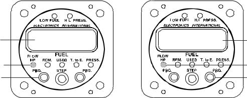
Low Fuel Warning LED |
High/Low Aux Warning LED |
12.3 |
Gal/Hr |
LCD Display |
|
||
|
|
Display Mode Indicator LEDs 
Left Program Button |
|
Right Program Button |
(Fuel to Destination on the FP-5L) |
|
(Fuel Reserve on the FP-5L) |
|
|
Step Switch (selects modes) |
|
|
3

In addition to these seven display modes both units have the following pilot programmable settings (used to set up the display and alarms): Display in Gallons, British (Imperial) Gallons, Pounds or Liters; Fuel Remaining; Auto Calibrate the K Factor; two Low Fuel Alarms; Time to Empty Alarm; Reoccurring Fuel Used Alarm; High and Low AUX Alarm. Also, both units have Power-Up Programmable Settings that are used to configure the instrument for your personal preferences, aircraft and engine. Although the FP-5 and FP-5L are simple to operate, the pilot programmable settings make them very effective and sophisticated fuel management systems.
Note: After the FP-5(L) has been installed in an aircraft it should be programmed initially as described in the "Power-Up Programming" section of this Manual.
Displays , Warning LEDs and Alarms:
1. Digital LCD Display and LED Display Mode Indicators:
If the digital LCD display backlight has been permanently powered up (as recommended), the display will be easier to see during low ambient light conditions and at night. In direct sunlight the digital LCD display is easy to see.
During night operation the green LED Display Mode Indicators may be too bright. If the LED Dimming Line on the FP-5(L) is connected to your panel light rheostat, turning the rheostat up will dim the LEDs. If the LED Dimming Line is connected to E.I.'s CP-1 (LED Intensity Control Pot), the Pot will control the LED intensity, independent of other instrument lights. The two red Warning LEDs will always be displayed at full intensity.
2. Low Fuel Warning LED:
There are four pilot-programmable alarms that will blink the red Low Fuel Warning LED when violated. The following describes how each alarm affects the Low Fuel Warning LED:
A.First Low Fuel Alarm: This alarm should be set as a reminder (example: 1/3 tank level). When the Alarm Limit is violated the red Low Fuel Warning LED will start to blink. Pushing any button or switch will stop the blinking and turn off the Warning LED. Also, a bar in the upper left corner of the display will be shown when displaying “REM”.
Low Fuel Warning LED (blinking)
Upper Bar Showing |
11.9 Gal |
|
Note: In this example, the First Low Fuel Limit was set to 12.0 Gallons. The blinking Low Fuel Warning LED indicates that the limit was violated.
Mode: "REM." 

4
B.Second Low Fuel Alarm: This alarm should be set as a warning (example: 5 gallons). When the Alarm Limit is violated the red Low Fuel Warning LED will start to blink. Pushing any button or switch will stop the blinking and the LED will go solid red. Also, a bar in the lower left corner of the display will be shown when displaying “REM”.
C.Time to Empty Alarm: This alarm may be set for a time to empty value (example: 1 hour). When the fuel flow and fuel remaining results in less than one hour of fuel on board (as per example) the Alarm Limit is violated and the red Low Fuel Warning LED will start to blink. Pushing any button or switch will stop the blinking and turn off the Warning LED. Also, a bar in the upper left corner of the display will be shown when displaying "T.toE."
D.Reoccurring Fuel Used Alarm: This alarm may be set for a fuel used value (example: 10 Gal). If the alarm was activated with 40 gallons of fuel remaining, there will be an alarm at 30, 20 and 10 gallons of fuel remaining in the tank. This feature reminds you to switch tanks for balancing the wings (based on weight, not time) or it may be used to remind you to check your fuel levels at set intervals. When the Alarm Limit is violated the red Low Fuel Warning LED will start to blink. Pushing any button or switch will stop the blinking and turn off the Warning LED.
Note: See the "Pilot Programmable Modes" section of this manual to set the alarms.
3. H/L AUX Warning LED:
There are pilot programmable High and Low Alarm Limits that will blink the red "H/L AUX Warning LED when violated. Pushing any button or switch will cause the LED to stop blinking and become solid red. If the High Limit is violated, a bar in the upper left corner of the display will be shown when displaying “AUX” If the Low Limit is violated, a bar in the lower left corner of the display will be shown when displaying “AUX” See the "Pilot Programmable Modes" section of this manual to set the alarm limits.
4. Power-Up:
When the aircraft master switch is turned on, the FP-5(L) will perform a self-diagnostics test and flash the red warning LEDs. This allows you to check the Warning LEDs for proper operation.
After power-up, the FP-5(L) will blink the "REM" (Fuel Remaining) LED, and display the fuel remaining in the tank(s). The “REM” LED will continue to blink until any button or switch is pushed. The blinking “REM” LED is intended as a reminder to update the FP-5(L) if you’ve added fuel to the aircraft since your last flight (see “REM” Display Mode).
5
Display Modes and Operating Features:
The following chart is an overview of the Display Modes and Pilot Programmable Settings available.
|
|
Display Mode (indicated by a green LED) |
|
|||
|
|
|
|
|
|
|
|
FLOW |
|
|
|
T. to E. |
|
|
HP |
|
REM |
USED |
MPG |
AUX |
|
|
|
|
|
|
|
Main Display |
Fuel Flow |
|
Fuel Remaining |
Fuel Used |
Time to mpty |
Displays |
(select with |
|
since Fill Up |
one of many |
|||
(17.3 gal/Hr) |
|
(23.7 gal) |
(1:22) |
|||
"STEP" Switch) |
|
(16.3 gal) |
functions. |
|||
|
|
|
|
|||
|
|
|
|
|
|
|
|
% |
|
|
Fuel Used for |
(FP-5L only) |
|
|
|
|
Nautical Miles |
|
||
|
Horsepower |
|
|
the Flight |
|
|
|
|
|
per Gallon |
|
||
Alternate Display |
(HP75) |
|
|
(F 7.2 gal) |
|
|
|
|
(n 9.3) |
|
|||
|
|
|
|
|
||
(tap either "PRG" |
|
|
|
|
|
|
|
|
|
|
(FP-5L only) |
|
|
button) |
|
|
|
|
|
|
|
|
|
|
|
Statute Miles |
|
|
|
|
|
|
per Gallon |
|
|
|
|
|
|
( 10.7) |
|
|
|
|
|
|
|
|
|
Set FP-5(L) |
|
|
Set the First |
|
|
|
to Display in |
|
|
Set the Time to |
Set the High |
|
Pilot |
|
Add Fuel |
Low Fuel |
|||
Gal, Br Gal, |
|
mpty Alarm |
Aux Alarm |
|||
|
|
Alarm |
||||
Programmable |
Lbs or Ltrs. |
|
|
|
|
|
|
|
|
|
|
||
Settings |
|
|
|
|
|
|
|
|
|
|
Set the |
|
|
(push both "PRG" |
|
|
|
Set the |
|
|
buttons) |
|
|
Auto Calibrate |
Reoccurring |
Set the Low |
|
|
|
Second Low |
||||
|
|
|
the K Factor |
Fuel Used |
Aux Alarm |
|
|
|
|
Fuel Alarm |
|||
|
|
|
|
Alarm |
|
|
|
|
|
|
|
|
|
|
|
|
|
|
|
|
1. “FLOW / HP” Display Modes:
By pushing the mode select switch to the right or left, you can select the various display modes. When in the "Flow / HP" mode, tapping either "PRG" button will cause the display to toggle between displaying Fuel Flow and percentage of Horsepower. When displaying Horsepower, "HP" will be shown at the left of the display.
Flow Displayed |
12.3 |
Gal/Hr |
HP75 |
Displayed. |
|
|
|
75% Horsepower |
|
Flow / HP Mode |
|
|
|
Flow / HP Mode |
Tap either Prg |
|
|
|
Tap either Prg |
Button to toggle |
|
|
|
Button to toggle |
between the two |
|
|
|
between the two |
displays. |
|
|
|
displays. |
6

When displaying Fuel Flow, the FP-5(L) will operate as follows:
A.When set to display in Gallons the display will read in .1 Gal/Hr increments up to 199.9 Gal/Hr.
B.When set to display in Imperial Gallons the display will read in .1 Gal/Hr increments up to 162.0 Gal/Hr.
C.When set to display in Pounds the display will read in 1 Lb/Hr increments up to 1199 Lbs/Hr.
D.When set to display in Liters the display will read in 1 Ltr/Hr increments up to 749 Ltrs/Hr.
Special algorithms in the microprocessor are used to insure a quick response and a stable display. Also, there are two programmable filter settings that will affect the stability and response of the fuel flow readings (see the “Power-up Programmable Settings” section of this manual).
The accuracy of the displayed fuel flow is affected by the value of the K Factor. The K Factor sets the calibration of the instrument to match the flow transducer and the variations in the installation. The K Factor may be changed by entering the "Power-up Programming Mode" or it can be changed automatically by entering the "Auto Calibration Mode."
When displaying % Horsepower, the FP-5(L) will operate as follows:
A. Horsepower is calculated from fuel specifics (as is done on engine dyno's) which takes into account manifold
pressure, RPM, altitude and OAT. Almost all spark ignition combustion engines have a fuel specific of approximately .10 gallons per H.P. per hour at full rich mixture. The "Power-Up Programming Mode" allows you to calibrate the FP-5(L) to match your engine at a full rich mixture.
B. If the AUX Channel is used to monitor an EGT, the FP-5(L) will compensate the displayed horsepower as your lean your engine. Otherwise, as you lean for max power (100° to 150°F rich of peak EGT) you may see a 5% to 8% drop in the displayed horsepower when you should see an approximately 3% increase in horsepower. Therefore, only display "HP" when your engine is running at full rich mixture settings.
With EGT compensation on the AUX Channel, the FP-5(L) can be calibrated to your engine when leaned (see the "Power-Up Programmable Settings" section in this manual).
C.The FP-5(L) was designed to display in % Horsepower (1% resolution). It is possible to calibrate the FP-5(L) to display in raw horsepower. See the "Power-Up Programming Mode."
Warning: You should never lean your engine with power settings over the factory recommended level (generally 65% to 75% power). Leaning with high power settings can cause detonation. Always verify your power level with engine charts before leaning. As you lean past maximum horsepower (100°F to 150°F rich of peak EGT) your engine will lose power and the FP-5(L) will show this.
7
 Loading...