


Primary Glass Panel Engine Monitor
(with In-Flight Data)
MVP-50P
Installation Instructions
II 0425051 Rev. I: 02/05/09***
You must read this manual before installing or operating the instrument. This manual contains warranty and other information that may affect your decision to install this product and/or the safety of your aircraft.
The MVP-50P is a FAA Approved Primary Replacement for Engine and Aircraft System Instruments
5.55" W x 5.15" H x 2.4" D
Model #:
 ElectronicsS/N: International Inc. ®
63296 Powell Butte Hwy • Bend, OR 97701 • (541) 318-6060 • Buy-EI.com

Important Notice
***** MUST READ *****
Page 1 of 4
If you think it is not important to read this manual, you're wrong! This manual contains important operating information that may affect the safety of the pilot, passengers, aircraft, operation of the system or time to install the system. You MUST read the manual prior to installing this system. Any deviation from these installation instructions is the sole responsibility of the installer and should be done in accordance with AC 43.13.
Read the Warranty/Agreement. There is information in the Warranty/Agreement that may alter your decision to install this product. If you do not accept the terms of the Warranty/Agreement, do not install this product. This product may be returned for a refund. Contact Electronics International Inc. for details.
If you are not an FAA Certified Aircraft Mechanic familiar with the issues of installing aircraft EGT, CHT, RPM, M.P,Volt, Amp, Oil Temperature and Pressure instruments, Do Not attempt to install this instrument. The installer should use current aircraft standards and practices to install this system (refer to AC 43.13).
If the installer does not have the skills, knowledge, tools, equipment or facility, to perform and determine whether the installation of this product is safe, reliable and accurate and to determine whether this product is operating properly after installation, DO NOT INSTALL THIS PRODUCT. If the owner/pilot and/ or installer are unwilling to take the responsibility for the installation and operation of this product, DO NOT INSTALL THIS PRODUCT. This product may be returned for a refund. Contact Electronics International Inc. for details.
By installing this product, the aircraft owner/pilot and installer agree to hold Electronics International Inc. harmless and in no way responsible for monetary compensation, including punitive damages for any incident, harm and/or damage associated with this product. If you do not agree to the above, DO NOT INSTALL THIS PRODUCT. This product may be returned for a refund. Contact Electronics International Inc. for details.
Electronics International Inc. is not liable or responsible for a pilot’s action or any situation that results in personal injury, property damage, missed commitments, lack of use of an aircraft or any expenses incurred due to: product failure, inaccuracy in displayed data or text files, display or display format issues, software bugs or problems, upgrade or customization issues, misinterpretation of the display, warning and/or limit settings, calibration problems, installation issues (leaks, mis-wiring, obstructions, damage to aircraft or components, incorrect installation of any parts, wrong parts, parts that don’t fit, etc.) or any other issues related to the installation or operation of this product. All of the above are solely the pilot’s and/or installer’s responsibility. The pilot must understand the operation of this product before flying the aircraft. The pilot must not allow anyone to operate the aircraft that does not know the operation of this product. The pilot must keep the instrument Operating Instructions in the aircraft at all times. If you do not agree to the above, DO NOT INSTALL THIS PRODUCT. This product may be returned for a refund. Contact Electronics International Inc. for details.
Do not install a non-certified MVP-50P (MVP) in a certified aircraft. A certified MVP lists the applicable TSO numbers at the bottom of the Model Label.

Important Notice
***** MUST READ *****
Page 2 of 4
Before starting the installation make sure the unit will fit in the location you intend to install it without obstructing the operation of any controls.
The MVP stores general information, checklists, weight and balance information and more. The pilot and/or owner of the aircraft is responsible for verifying that this information is accurate and complete. The pilot and/or owner is further responsible, on a regular basis, for maintaining this information and insuring that it is up to date and accurate. If the pilot and/or owner of the aircraft is unable or unwilling to do this, the files must be deleted.
Before using the Weight and Balance screen check that the “Weight and Balance Setup” data in the MVP System Configuration Menu is accurate. Always verify the MVP weight and balance data with you aircraft’s POH.
Verify the horsepower displayed on the MVP is accurate, as compared to your aircraft's POH and/or engine TC data.
The MVP must be calibrated to the aircraft fuel system and the MVP's accuracy must be verified before flying the aircraft.
The accuracy and proper operation of each function displayed on the MVP should be verified before the aircraft is released for flight.
When the installation is finished, inspect the system for loose fittings, connections, clamps, probes and inspect for leaks, chafing, obstructions, heat damage and anything that may cause unsafe flight before the 1st run-up, after the 1st run-up and after the first flight.
The MVP allows the pilot to enter checklists, flight plans and general information through the USB port. This data must be verified for its accuracy (by the pilot) before it is used.
Before allowing the aircraft to be flown, verify the instrument markings displayed on the MVP screens are accurate with the aircraft’s POH for every function displayed on the MVP.
Before allowing anyone to operate the aircraft read the Operating Manual including the Important Notice there in. Keep the Operating Instructions in the aircraft at all times.
The use of the MVP requires recurring training for any pilot who will be flying the aircraft in which it is installed. Recurring training should include reading the MVP Installation Manual and Operations Manual and seeking a flight instructor for proper interpretation of information being displayed to the pilot.
It is important the password(s) be changed (by the installer) to a unique and protected number before the first flight. If setup or calibration data is inadvertently or improperly changed, there could be inaccurate readings that may lead to improper operation of the aircraft or engine. This could result in engine damage and/or an emergency situation. The password must be protected from dissemination to unauthorized persons.

Important Notice
***** MUST READ *****
Page 3 of 4
Fuel LevelAccuracy Limitations:
The accuracy limitations of the MVP are listed below. It is the pilot/owner’s obligation to make anyone flying the aircraft aware of these limitations.
1. Angle of Attack - The MVP must be calibrated with the aircraft in a cruise angle of attack. If the aircraft is in an angle of attack other than cruise, the MVP may display inaccurate fuel levels (depending on the mounting location and type of sensor used). If your aircraft does not sit at a cruise angle of attack when on the ground, it may not display accurate fuel levels. Test your aircraft at different angles of attack to see the affects on the MVP fuel level readings.
2. Full Fuel Readings - As a tank is filled the fuel sensor may not be able to detect the fuel entering the upper corners of the fuel tank. If this is the case with your sensor, the MVP will display lower fuel levels than the actual fuel in the tanks when the tanks are full. When the fuel level drops to a point where the fuel sensor starts to detect a change, the displayed fuel level should be accurate.
Check the accuracy of your system by comparing the displayed fuel levels on the MVP to the fuel levels listed in the flight manual at each fill up.
3. Low Fuel Readings - Do not rely on the MVP to determine the fuel level in the tank for an indicated tank level below 1/8. You should always fly the aircraft in such a manner as to maintain at least the FAA minimum fuel requirements in the aircraft at all times.
4. Improper Calibration - If the MVP has not been properly calibrated it will not display accurate fuel levels in the tanks. It is important you verify the accuracy of the MVP. Always crosscheck your measured fuel levels in the tanks with the readings on the MVP before each flight.
5. Poor Connections - Poor connections between the wires leading from the EDC to the fuel sensors can become intermittent. An intermittent connection most likely will show up as wandering or inaccurate readings on the MVP. Always crosscheck your measured fuel levels in the tanks with the readings on the MVP before each flight.
6. Defective Fuel Level Sensors - Fuel sensors can become intermittent or change resistance with age. It is not uncommon to find intermittent problems even in new sensors. An intermittent problem with a fuel sensor most likely will show up as wandering or inaccurate readings on the MVP.
Always crosscheck the measured fuel levels in the tanks with the readings on the MVP at each fill up.
If you ever find an inaccuracy issue or any other |
problem with a fuel level display on |
the MVP, troubleshoot and fix the problem before |
flying the aircraft. |
If you do not agree to all of the above, DO NOT INSTALL THIS PRODUCT. This product may be returned for a refund. Contact Electronics International Inc. for details.

Important Notice
***** MUST READ *****
Page 4 of 4
ImportantFuelLevelConsiderations:
DO NOT RELY SOLELY ON THE FUEL LEVEL DISPLAYED ON THE MVP TO DETERMINE THE FUEL LEVELS IN THE AIRCRAFT. The use of the MVP does not eliminate or reduce the necessity for the pilot to use good flight planning, preflight and in-flight techniques for managing fuel. It is important the pilot adopt the practices listed below. If you are not familiar with these techniques, contact the FAA to acquire proper training.
1.A copy of the Operating Manual must be in the aircraft at all times.
2.Flight Planning - Always calculate the fuel requirement for each leg of a flight, including any alternate plans for bad weather. Keep this information available in the aircraft during the flight. Keep a chart of the published fuel flows for various flight/engine conditions in the aircraft. Keep a chart of the measured fuel flows for various flights in the aircraft. Measured fuel flows can be considerably different from published figures. This usually is due to old, inaccurate engine instruments.
3.Preflight - Do not rely on the MVP to determine the fuel level in the fuel tanks. The pilot must visually check/measure the fuel levels in the tanks before every takeoff.
Crosscheck the measured fuel levels with the displayed levels on the MVP. Also, crosscheck these levels with the fuel requirements for the flight listed in your flight plan.
4.In Flight - Make the MVP part of your normal instrument scan. Crosscheck the fuel levels displayed on the MVP with your flight plan at each leg of the flight or every 30 minutes
(whichever happens first). If there is a discrepancy, land the aircraft at the nearest airport and verify the fuel levels. Discrepancies should be taken seriously.
5.New Pilot or Owner of the Aircraft - If there is a new pilot or owner of the aircraft, it is the previous aircraft pilot/owner’s responsibility to insure the new pilot has read this manual and is aware of any accuracy limitations and other important considerations. All limitations and operating characteristics learned from operating the MVP must be passed on to the new pilot/owner.
If you do not agree or are unwilling to comply with the information/requirements contained within this Important Notice, DO NOT INSTALL THIS PRODUCT. This product may be returned for a refund. Contact Electronics International Inc. for details.
|
|
Contents |
|
|
|
(Page 1 of 3) |
|
Warranty/Agreement-------------------------------------------------------------------------------------- |
1A |
||
1.0 System Overview ------------------------------------------------------------------------------------- |
2 |
||
|
1.1 MVP Description ------------------------------------------------------------------------------ |
4 |
|
|
1.1.1 |
MVP Display ---------------------------------------------------------------------------- |
4 |
|
1.1.2 EDC-33P --------------------------------------------------------------------------------- |
4 |
|
|
1.1.3 |
Probes, Transducers and Modules --------------------------------------------------- |
5 |
|
1.1.4 |
Wiring & Extension Cables ----------------------------------------------------------- |
5 |
1.2 |
Operational |
Overview ------------------------------------------------------------------------------- |
5 |
1.3 |
Installation |
Overview --------------------------------------------------------------------------------- |
5 |
1.4 |
Password Protection ---------------------------------------------------------------------------------- |
6 |
|
|
1.4.1 Level #1 Password (Maintenance) ------------------------------------------------------- |
6 |
|
|
1.4.2 Level #2 Password (OEM) ---------------------------------------------------------------- |
7 |
|
2.0 Hardware Installation -------------------------------------------------------------------------------- |
9 |
||
|
2.1 Important Information and Initial Check Out: ------------------------------------------- |
11 |
|
|
2.2 Review the "EDC Wiring Work Sheet:" -------------------------------------------------- |
12 |
|
|
2.3 Verify you have all the necessary Probes, Modules, Transducers and Cables: ----- |
12 |
|
|
2.4 Install the MVP Display: --------------------------------------------------------------------- |
12 |
|
|
2.5 Install the Post Lights: ------------------------------------------------------------------------ |
13 |
|
|
2.6 Install the Temperature Probes: ------------------------------------------------------------- |
13 |
|
|
2.7 Install the Pressure Transducers: ----------------------------------------------------------- |
15 |
|
|
2.8 Install the Interface Circuit for Annunciators -------------------------------------------- |
19 |
|
|
2.9 Install the Interface Circuit for Flaps and Trim ------------------------------------------ |
20 |
|
|
2.10 Install the Interface Circuit for the Gear Position, Unsafe Indicator and Gear --- |
20 |
|
|
2.11 Install the CO-Guardian CO Detector -------------------------------------------------- |
21 |
|
|
2.12 Install the Shunt: ----------------------------------------------------------------------------- |
21 |
|
|
2.13 Install the Fuel Flow Transducer: --------------------------------------------------------- |
24 |
|
|
2.14 Install the P-300C Fuel Level Probes (OEM or Experimental) --------------------- |
30 |
|
|
2.15 Install the P-300M Fuel Levl Sender: ---------------------------------------------------- |
30 |
|
|
2.16 Install the Resistive Fuel Level Module (RFLM-4-X): ------------------------------- |
31 |
|
|
2.17 Install the Voice Alarm Control Panel (OEM or Experimental): ------------------- |
31 |
|
|
2.18 Install the Intensity Control Pot (Optional): -------------------------------------------- |
31 |
|
|
2.19 Install the Master Warning (red) and Caution (yellow) Lights: ----------------------- |
32 |
|
|
2.20 Install the EDC-33P: ------------------------------------------------------------------------ |
32 |
|
3.0 Install the EDC Wire Harnesses and Route Wires ---------------------------------------------- |
33 |
||
|
3.1 Attach the three EDC 37-pin wire harnesses to the EDC: ---------------------------- |
35 |
|
|
3.2 Connect the EDC Harness to the Temperature Probes: -------------------------------- |
35 |
|
|
3.3 Connect the EDC Harness to the Pressure Transdcueres: ----------------------------- |
35 |
|
|
3.4 Connect the EDC Harness to the Shunt: -------------------------------------------------- |
36 |
|
Contents
(Page 2 of 3)
3.5 Connect the EDC Harness to the Fuel Flow Transducer: ----------------------------- |
36 |
||
3.6 Connect the RFLM-4-x Harness to the EDC Connector and to the Resistive |
|
||
|
Fuel Level Sensor: ------------------------------------------------------------------------------ |
37 |
|
3.7 Connect the EDC Harness to the Capacitive Fuel Level Probe: ---------------------- |
37 |
||
3.8 Connect the EDC Harness to the P-300M Fuel Level Senders: ---------------------- |
38 |
||
3.9 Connect the EDC Harness (Volts Meassurement Pin) to the Bus: ------------------- |
38 |
||
3.10 Connect the EDC Harness to the RPM Signals: ----------------------------------------- |
38 |
||
3.11 Setup the EDC for a 4 or 6-Cylinder Engine: ------------------------------------------- |
38 |
||
3.12 Connect the EDC Harness to the VI-221's (Voltage Interface Units): ------------- |
38 |
||
3.13 Connect the EDC Harness to Power and Ground: ------------------------------------ |
39 |
||
3.14 Route the EDC RS422 Wires to the MVP Connector: -------------------------------- |
39 |
||
4.0 Install the MVP Wire Harness and Route the Wires ------------------------------------------- |
40 |
||
4.1 Attacht the MVP 25-pin D-sub Connector to the MVP: ------------------------------- |
42 |
||
4.2 Connect the EDC RS422 Wires to the MVP RS422 Wires: --------------------------- |
42 |
||
4.3 Connec the MVP Harness to the Master Warning and Caution Lights: ------------- |
42 |
||
4.4 Connec the MVP Harness to the Voice Alarm Control Panel (AV-17CP): --------- |
42 |
||
4.5 Connec the MVP Harness to the Audio Panel: ------------------------------------------- |
43 |
||
4.6 Connec the MVP Harness to the External Intensity Control Pot (CP-1): ----------- |
43 |
||
4.7 Connec the MVP Harness to the Moving Map Data Out from the GPS: ----------- |
43 |
||
4.8 Connec the MVP Harness to the Fuel Data Input on the GPS: ----------------------- |
43 |
||
4.9 Connec the MVP "Transmit Lockout Input" pin to the Transmit Key: ------------- |
44 |
||
4.10 Connec the MVP Harness to Power and Ground: ------------------------------------- |
44 |
||
4.11 Connec the MVP Harness to the CO-Guardian CO Detector: ---------------------- |
44 |
||
5.0 Mandatory System Setup and Checkout --------------------------------------------------------- |
45 |
||
5.1 |
Power-On Checkout -------------------------------------------------------------------------- |
47 |
|
5.2 |
Perform all Steps Listed in the "MVP-50P Setup Checklist" ------------------------ |
47 |
|
5.3 Ground Run Checkout ------------------------------------------------------------------------ |
47 |
||
5.4 First Flight Checkout -------------------------------------------------------------------------- |
48 |
||
5.5 Read the "Warranty/Agreement" and the "Important Notice" ----------------------- |
48 |
||
6.0 Installation Data -------------------------------------------------------------------------------------- |
50 |
||
6.1 Instructions for Continued Airworthiness (ICA): ----------------------------------------- |
52 |
||
6.2 Airworthiness Limitations: -------------------------------------------------------------------- |
52 |
||
6.3 Working With Connectors: -------------------------------------------------------------------- |
52 |
||
6.3.1 |
Installing a Red Slip-on Connector onto a TC or Tin Copper Wire: ---------- |
53 |
|
6.3.2 |
Installing a Yellow Precision TC Connector onto a TC Wire: ----------------- |
54 |
|
6.3.3 |
Installing a D-sub Pin onto a TC or Tin Copper Wire: -------------------------- |
54 |
|
MVP-50P 25-pin D-sub Connector Wiring Diagram ----------------------------------- |
56 |
||
EDC Wiring Work Sheet Top Connector ---------------------------------------------- |
57 |
||
EDC Wiring Work Sheet Middle Connector ------------------------------------------- |
58 |
||
EDC Wiring Work Sheet Bottom Connector ------------------------------------------- |
59 |
||
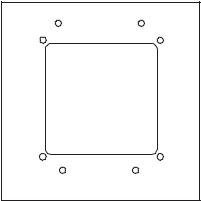
MVP Aircraft Panel Cutout ------------------------------------------------------------ |
60 |
||
EDC Template ------------------------------------------------------------------------- |
61 |
||
Contents |
|
(Page 3 of 3) |
|
7.0 Troubleshooting --------------------------------------------------------------------------------------- |
62 |
7.1 MVP or EDC Problem ------------------------------------------------------------------------ |
64 |
7.2 Pressure Problem with one Function ------------------------------------------------------- |
65 |
7.3 Temperature Problem on all Channels ----------------------------------------------------- |
65 |
7.4 Temperature Problem with one Function ------------------------------------------------- |
66 |
7.5 RPM Problem ----------------------------------------------------------------------------------- |
66 |
7.6 Fuel Flow Problem ----------------------------------------------------------------------------- |
67 |
7.7 Amp Problem ----------------------------------------------------------------------------------- |
68 |
7.8 Resistive Fuel Level Problem ---------------------------------------------------------------- |
68 |
7.9 Capacitive Fuel Level Problem -------------------------------------------------------------- |
79 |
7.10 Voltage Problem ------------------------------------------------------------------------------ |
70 |
7.11 Annunciator Problem ------------------------------------------------------------------------ |
70 |
8.0 Technical Data ---------------------------------------------------------------------------------------- |
73 |
Specifications / Features ---------------------------------------------------------------- |
75 |
DO-160 Environmental Qualification Form --------------------------------------------------- |
83 |
STC and AML ---------------------------------------------------------------------------------------- |
86 |
Appendix ---------------------------------------------------------------------------------------------------- |
A |
A1.0 Appendix: Interfacing the EDC to a Princeton Capacitive Fuel Level Probe ------- |
A1.0 |
A2.0 Appendix: Interfacing the EDC to a Centroid / Sky Sports Capacitive Fuel |
|
Level Probe ---------------------------------------------------------------------- |
A2.0 |
A3.0 Appendix: LASAR Ignition RPM Filter -------------------------------------------- |
A3.0 |
A4.0 Appendix: Connecting an EDC Input to a Custom Probe ------------------------- |
A4.0 |
A5.0 Appendix EDC-33P-8 for 7, 8, 9-Cylinder Engines and High RPM Engines ------ |
A5.0 |
A6.0 Appendix Connecting a Second EDC to the MVP -------------------------------- |
A6.0 |
A7.0 Appendix Connecting an EDC RPM Channel to a Lightspeed Plasma II or |
|
III Ignition ------------------------------------------------------------------------ |
A7.0 |
Warranty / Agreement
Electronics International Inc. (EI) warrants this instrument and system components to be free from defects in materials and workmanship for a period of one year from the user invoice date. EI will repair or replace any item under the terms of this Warranty provided the item is returned to the factory prepaid.
1.If you do not agree to and accept ALL the terms of this Warranty/Agreement, DO NOT Install This Product. You may return the product for a refund, contact Electronics International Inc. for details.
2.Electronics International Inc. is not liable or responsible for a pilot’s action or any situation that results in personal injury, property damage, missed commitments, lack of use of an aircraft or any expenses incurred due to: product failure, inaccuracy in displayed data or text files, display or display format issues, software bugs or problems, upgrade or customization issues, misinterpretation of the display, warning and/or limit settings, calibration problems, installation issues (leaks, mis-wiring, obstructions, damage to aircraft or components, incorrect installation of any parts, wrong parts, part that don’t fit, etc.) or any other issues related to the installation or operation of this product. All of the above are solely the pilot’s and/or installer’s responsibility. The pilot must understand the operation of this product before flying the aircraft. The pilot will not allow anyone to operate the aircraft that does not know the operation of this product. The pilot will keep the instrument's Operating Instructions in the aircraft at all times.
By installing this product, the aircraft owner/pilot and installer agree to hold Electronics International Inc. harmless and in no way responsible for monetary compensation, including punitive damages for any incident, harm and/or damage associated with this product (including but not limited to the ones listed above). If you do not agree to any part of this Warranty/Agreement, DO NOT INSTALL THIS PRODUCT.
3.This Warranty/Agreement shall not apply to any product that has been repaired or altered by any person other than Electronics International Inc., or that has been subjected to misuse, accident, incorrect wiring, negligence, improper or unprofessional assembly or improper installation by any person. This warranty does not cover any reimbursement for any person’s time for installation, removal, assembly or repair. Electronics International retains the right to solely determine the reason or cause for warranty repair.
4.This warranty does not extend to any machine, vehicle, boat, aircraft or any other device to which the Electronics International Inc. product may be connected, attached, interconnected or used in conjunction with in any way.
5.Personal injury or property damage due to misinterpretation or lack of understanding of this product is solely the pilots' responsibility. The pilot must understand all aspects of the operation of this product before flying the aircraft. If he/she does not, he or she agrees to seek training from a knowledgeable instructor. The pilot also agree that no one will be allowed to operate the aircraft that does not know the operation of this
product and will Keep the Operating Instructions in the aircraft at all times.
6.The obligation assumed by Electronics International Inc. under this warranty is limited to repair, replacement or refund of the product, at the sole discretion of Electronics International Inc.
7.Electronics International Inc. is not liable for expenses incurred by the customer or installer due to factory updates, modifications, improvements, changes, or any other alterations to the product that may affect the form, fit, function or operation of the product.
More On Back of this Page
1A
8.Electronics International is not responsible for shipping charges or damages incurred under this Warranty.
9.No representative is authorized to assume any other liability for Electronics International Inc. in connection with the sale of Electronics International Inc. products.
10. You must read the entire Installation and Operating Instructions for this instrument. If you do not agree to and accept the terms of this Warranty/Agreement and the responsibilities set forth in these manuals, DO NOT install this product, contact E.I. for a refund.
This Warranty is made only to the original user. THIS WARRANTY IS IN LIEU OF ALL OTHER
WARRANTIES OR OBLIGATIONS: EXPRESS OR IMPLIED. MANUFACTURER EXPRESSLY DISCLAIMS ALL IMPLIED WARRANTIES OF MERCHANTABILITY OR FITNESS FOR A PARTICULAR PURPOSE. PURCHASER AGREES THAT IN NO EVENT SHALL MANUFACTURER BE LIABLE FOR SPECIAL, INCIDENTAL OR CONSEQUENTIAL DAMAGES, INCLUDING LOST PROFITS OR LOSS OF USE OR OTHER ECONOMIC LOSS. EXCEPT AS EXPRESSLY PROVIDED HEREIN, MANUFACTURER DISCLAIMS ALL OTHER LIABILITY TO PURCHASER OR ANY OTHER PERSON IN CONNECTION WITH THE USE OR PERFORMANCE OF MANUFACTURER’S PRODUCTS, INCLUDING SPECIFICALLY LIABILITY IN TORT.
1B
|
1.0 |
System Overview |
|
1.1System Description
1.1.1MVP Display:
1.1.2EDC-33P:
1.1.3Probes, Transducers and Modules:
1.1.4Wiring & Extension Cables:
1.2Operational Overview:
1.3Installation Overview:
1.4Password Protection:
1.4.1Level #1 Password (Maintenance):
1.4.2Level #2 Password (OEM/Experimental):
2

1.1 System Description:
The MVP-50P Glass Panel Engine Monitor installation consists of four major components: the MVP Display, the Engine Data Converter (EDC-33P), the Probes, Transducers & Modules, and the Wiring and Extension Cables.
1.1.1 MVP Display:
|
To |
|
|
|
Pwr & Gnd |
Master |
|
Master |
GPS |
||
Warning |
Audio Panel |
Caution |
|
Light |
|||
Light |
|
||
|
|
The MVP-50P (MVP) display measures 5.55" wide by 5.15" high by 2.4" deep and is designed to be mounted from behind the aircraft instrument panel. The MVP could be mounted onto a sub-panel which would then be mounted to the aircraft instrument panel from the front. The installation location of the MVP display on the aircraft panel and the method used to install the display will be a primary consideration in your decision to install the MVP.
The 25-pin D-sub connector on the back of the MVP display is used to interface the MVP to the EDC33P, Power & Ground, GPS, Master Warning and Caution Lights and Audio Panel (experimental only).
1.1.2 EDC-33P:
The EDC-33P (Engine Data Converter, "EDC") converts all of the engine and aircraft system signals into serial data. This data is transmitted to the MVP display via two wires (RS422). If a second EDC is installed, one of the EDC data lines will be connected to a RS232 channel on the MVP. The EDC measures 4.5" long by 3.5" wide by 2.2" high and is to be mounted on cockpit side of the firewall or in an equipment bay. The EDC reduces the wire bundle to the instrument panel by over 100 wires. There are three 37-pin D-sub connectors that interface the EDC to the various probes, transducers and modules.
The EDC’s temperature and fuel level inputs can be used to monitor voltage outputs from almost any transducer. In this way almost any function can be displayed on the MVP.
Up to two EDC’s can be connected to the MVP display. This significantly increases the total number of functions that can be displayed on the MVP.
4
1.1.3 Probes, Transducers and Modules:
The various probes, transducers and modules are mounted in the aircraft at appropriate locations.
1.1.4 Wiring & Extension Cables:
The extension cables and wiring provide the connections from the probes, modules or direct connections to the EDC inputs. Once the Wiring and Extension Cables are installed into the aircraft they become semi-permanent. Everything else (MVP, EDC, Probes and Modules) can be easily disconnected and removed.
1.2 Operational Overview:
The MVP system measures a primary engine or aircraft function using a probe or transducer and displays that function on the MVP screen using the following steps:
A.A probe is mechanically connected to the aircraft and electrically connected to an EDC input. The pre-wired harness provides most of the electrical connections from the probes to the EDC inputs.
B.The EDC converts the signals from the probes to a digital format (RS422) and sends the data to the MVP. The EDC has 33 inputs. Many of these inputs can be used to monitor various types of functions.
C.The MVP receives the data from the EDC and the data is processed through the MVP as follows:
1.The data received for each EDC input is assigned a function name and probe. Function names and probes are set up for each EDC input in System Configuration Screen #1. Assigning a probe provides specific calibration algorithms. These algorithms can be modified in System Configuration Screen #5. Some functions have special calibration/setup screens (Bar Graph, Fuel Tank Calibration, Tach Time, Engine Hours, Flight Time, Pressure Altitude, Horsepower, Flaps, Trim, etc.).
2.The function is then placed on the Main or System Screen of the MVP. System Configuration Screens #2 or #3 allow the placement of the function to be selected for either the Main or System screen.
3.The analog and/or digital display of the function (with redlines, limits, colors, etc) is depicted on the appropriate screen. Redlines, limits, colors, units, blinking, master warnings and voice files can be set up for any function in Configuration Screen #4.
Much of the setup for the certified MVP is done at the factory and cannot be changed by the pilot or installer. See the following Password Protection Section for more information.
1.3 Installation Overview:
The installer should start the installation by reviewing the EDC Wiring Work Sheets. There are three work sheets, one for each of the 37-pin D-Sub connectors on the EDC. The work sheets are packaged with each of the three EDC wire harnesses. The work sheets provide a list of the functions and probes/transducers included with this kit. The installation is achieved by performing the following steps:
A.The MVP display is installed. The MVP can be mounted one of two ways: from behind the instrument panel or on a sub-panel, which is then mounted to the aircraft instrument panel from the front.
5
This method hides the cutout for the MVP case and makes a clean and good-looking installation. Electronics International has a MVP sub-panel avaliable (see E.I. Price List for more information).
B.Probes and Transducers are installed.
C.Control Panels, Pots and Warning Lights are installed.
C.The EDC is installed. The EDC should be installed on the inside of the cockpit or in an instrument bay. For a twin-engine aircraft it can be installed on the backside (not the engine side) of the firewall.
E.The Wire Harnesses are installed. The wire harnesses for the EDC and MVP are pre-wired and included in the kit.
F.Field Calibration/Setup steps are performed. Weight & Balance, Fuel Tanks, Horsepower, etc. functions are calibrated/setup. Calibration/Setup requires a password. See the following Password Protection section for more information.
G.System Checkout is performed.
1.4 Password Protection:
The MVP provides a number of screens for the pilot to use during flight, none of which require a password. It also provides many System Configuration Screens that are used to configure the MVP for a specific aircraft. Some of the aircraft functions (fuel level, flaps, trim, weight and balance, etc.) must be calibrated during installation and some must be set at the factory or by an OEM.
The MVP provides two levels of passwords for configuring and calibrating the unit.
1.4.1Level #1 Password (Maintenance):
The Level #1 password is for the installer or maintenance personnel. This password allows the installer to perform the following:
A.Delete Log Files.
B.Set up the Gear Warning.
C.Adjust the Recovery Factor.
D.Calibrate the Fuel Level for all Fuel Tanks.
E.Adjust the Aircraft’s Weight and Balance data.
F.Set the Fuel Weight, Tach Time and Engine Hours.
G.Set up the Serial Ports.
H.Disable the Bar Graph.
I.Calibrate Pressure Altitude.
J.Calibrate Flap and Trim indications.
For a non-certified MVP, the password is “00100.” For a certified MVP the password must be obtained from Electronics International Inc. To qualify for the maintenance password you must be a certified mechanic or a FAA approved shop.
6
The password protects the MVP from unauthorized access to calibration data. If calibration data is improperly changed, it could lead to engine or aircraft damage and/or personal injury. Once the MVP is installed and checked out, the password should be changed (on either the certified or non-certified unit) to a unique number and it should be protected from unauthorized access.
If the new password is lost or a new shop requires access to calibration data (as allowed by the Maintenance Password), Electronics International has a method of providing the Maintenance Password to any FAA authorized shop or certified mechanic.
1.4.2Level #2 Password (OEM/Experimental):
The Level #2 password is for the Factory, OEM’s, Certified Installers, or experimental users. This password allows access to all System Configuration Data. For a non-certified MVP, the password is “00100.” For a certified MVP the password is only released under a contract or agreement.
The password protects the MVP from unauthorized access to calibration data. If calibration data is improperly changed, it could lead to engine or aircraft damage and/or personal injury. Once the unit is installed and checked out, this password should be changed (Whether a certified or non-certified MVP) to a unique number and should be protected from unauthorized access.
7
|
2.0 |
Hardware Installation |
|
2.1Important Information and Initial Checkout:
2.2Review the "EDC Wiring Work Sheets:"
2.3Verify You Have all the Probes, Modules, Transducers and Cables:
2.4Install the MVP Display:
2.5Install Post Lights:
2.6Install the Temperature Probes:
2.7Install the Pressure Transducers:
2.8Install the Interface Circuit for Annunciators:
2.9Install the Interface Circuit for Flap and Trim Pots (OEM / Experimental):
2.10Install the Interface Circuit for the Gear Position, Unsafe Indicator and Gear Warning:
2.11Install the CO Detector, G-Sensor and/or Other Available MVP Options:
2.12Install the Shunt:
2.13Install the Fuel Flow Transducer:
2.14Install the EI P-300C Fuel Level Probes (OEM or Experimental Only):
2.15Install the EI P-300M Fuel Level Sender:
2.16Install the Resistive Fuel Level Module (RFLM-4-X):
2.17Install the Voice Alarm Control Panel (OEM or Experimental Only):
2.18Install the Intensity Control Pot (Optional):
2.19Install the Master Warning (red) and Caution (yellow) Lights:
2.20 Installing the EDC-33P: |
9 |
2.1Important Information and Initial Checkout:
A.The installer and aircraft owner must read the Warranty/Agreement before starting the installation. There is information in the Warranty/Agreement that may alter your decision to install this instrument. If you do not accept the terms of the Warranty/Agreement, do not install this instrument.
B.If you are not an FAA Certified Aircraft Mechanic familiar with the issues of installing
engine and aircraft instruments, Do not attempt to install this instrument. The installer should use current aircraft standards and practices to install this instrument (refer to AC 43.13).
C. Check that any |
necessary |
FAA |
Approvals are |
available |
for your |
aircraft before starting |
the installation. |
The STC |
and |
AML is located |
in section |
8 of this |
manual. |
D.Read the Installation Instructions entirely and resolve any issues you may have before starting the installation. This may eliminate any delays once the installation is started.
E.Inspect the contents of this package prior to installation. If the MVP-50P system is to be installed into a certified aircraft, check that the Model Number listed on the TSO label
incorporates the Aircraft ID for which it is to be installed. Each MVP-50P display is configured for a specific aircraft and should only be installed in that aircraft.
F.Do not install a non-certified MVP in a certified aircraft. A certified MVP lists the applicable TSO numbers at the bottom of the Model Label attached to the back panel of the MVP.
G. Before starting the installation make sure the instrument will fit in the intended installation location without obstructing the operation of any controls. CFR 23.1321(a) states, “Each flight, navigation, and powerplant instrument for use by any required pilot during takeoff, initial climb, final approach, and landing must be located so that any pilot seated at the controls can monitor the airplane’s flight path and these instruments with minimum head and eye movement.” AC 23.1311-1B provides one method (but not the only method) of complying with this CFR. AC 23.1311-1B recommends a powerplant instrument be installed within a distance of 21" from the pilot’s visual centerline to the middle of the instrument. The pilot’s visual centerline is a perpendicular line from the pilot’s eye to the instrument panel. In most aircraft, installing the MVP-50P to the right of the Radio Stack would be acceptable. In some aircraft, the visual centerline falls to the right of the Attitude Indicator.
If the powerplant instrument cannot be installed within 8" of the pilot’s visual centerline, AC 23.13111B recommends Master Caution and Warning Lights be installed. Installation of Master Caution and Warning Lights is covered in this manual.
H.Installing the MVP-50P may require an instrument (or two) to be moved to a new location. The MVP50P replaces eight or more primary instruments in the aircraft instrument panel, therefore moving an instrument to a new location may not be an issue. If the installer is unwilling or unable to find a location for the MVP-50P, Do Not Install the MVP-50P. The system may be returned for a refund.
I.If this instrument is to replace an existing gauge in the aircraft, it is the installer’s responsibility to move or replace any existing instruments or components in accordance with FAA approved methods and procedures (see AC 43.13).
J.An Installation Checklist is provided to assist the installation of the MVP system. It does not replace the instructions located in this manual.
11
2.2 Review the "EDC Wiring Work Sheets:"
There are a number of probes and extension cables that will need to be installed. The key to keeping the installation simple is to organize the work using the "EDC Wiring Work Sheets" supplied with this kit. Review the functions assigned to each EDC input on the EDC Wiring Work Sheets. The work sheets are prepared at the factory with the functions and probes already assigned.
2.3 Verify You Have all the Probes, Modules, Transducers and Cables:
The three EDC 37-pin D-sub connectors and the MVP 25-pin D-sub connector are pre-wired at the factory. The three EDC connectors are marked Top, Middle and Bottom. The EDC Wiring Work Sheets provide a list of the probes supplied with this kit.
A.Check that you have all the probes listed on the EDC Wiring Work Sheets.
B.Check that the three EDC 37 pin-D-sub wire harnesses are provided with the proper wires for each of the probes shown on the EDC Wiring Work Sheets.
C.Check that the MVP 25-pin D-sub wire harness is provided.
2.4 Install the MVP Display:
Before starting the installation make sure the instrument will fit in the location you intend to install it without obstructing the operation of any controls. Also, the pilot should have a clear view of the MVP display without any visual obstructions. The MVP display can be installed in one of two ways, depending on convenience or the installer's preference. The first method is the traditional method of installing the MVP display from behind the panel. An aircraft panel cutout drawing is provided at the back of this manual.
The second method is more suitable when an MVP display is to be mounted in an existing aircraft panel. This method requires creating a sub-panel slightly larger than the MVP display. The MVP display is mounted in the sub-panel and the sub-panel is mounted on the front of the existing aircraft panel. This allows the installer to rough-cut a hole in the aircraft panel to accommodate the MVP display. The sub-panel covers any imperfections in the cut hole. Also, the MVP display may easily be removed from the front of the aircraft panel. Electronics International has a precut MVP Sub-panel available. See EI’s Price List or contact EI for more information.
The sub-panel should be made from .062" (or thicker) aluminum and can be painted black or the same color as the aircraft panel. Four screws (6-32 or larger) to be located at the top and bottom of the sub-panel should be drilled to mount the sub-panel to the aircraft panel. If there is no room at the top
and bottom for mounting screws, they may be placed on the sides of the sub-panel.
MVP
Sub-panel
CFR 23.1321(a) states, “Each flight, navigation, and powerplant instrument for use by any required pilot during takeoff, initial climb, final approach, and landing must be located so that any pilot seated at the controls can monitor the airplane’s flight path and these instruments with minimum head and eye movement.” AC 23.1311-1B provides one method (but not the only method) of complying with this CFR. AC 23.1311-1B recommends a powerplant instrument be installed within a distance of 21" from the pilot’s
12
visual centerline to the middle of the instrument. The pilot’s visual centerline is a perpendicular line from the pilot’s eye to the instrument panel. In most aircraft, installing the MVP-50P to the right of the radio stack would be acceptable. In some aircraft, the visual centerline falls to the right of the Attitude Indicator.
If the powerplant instrument cannot be installed within 8" of the pilot’s visual centerline, AC 23.1311-1B recommends Master Caution and Warning Lights be installed. Installation of Master Caution and Warning Lights is covered in this manual.
Installing the MVP-50P may require an instrument (or two) to be moved to a new location. The MVP-50P replaces eight or more primary instruments in the aircraft instrument panel, therefore moving an instrument to a new location may not be an issue. If the installer is unwilling or unable to find a location for the MVP-50P, Do Not Install the MVP-50P. The system may be returned for a refund (contact EI for more information).
2.5 Install Post Lights:
If your aircraft does not currently have lighting that complies with CRF 23.1381, install a Post Light as follows:
Mount the Post Light approximately 1" above the center of the MVP-50 “PUSH – SELECT” knob and just to the left of the MVP-50 case.
2.6 Install the Temperature Probes:
Install only the Temperature Probes applicable for your configuration.
A. EGT Probe Installation:
Look at each exhaust stack and determine the best location at which all of the EGT probes can be mounted at the same distance down from the exhaust ports. The ideal location is 1 1/2", but ease of installation should prevail. Drill a 13/64" diameter hole in each exhaust stack. Insert the probe and tighten the hose clamp. As the hose clamp is heated and cooled, it will become loose as it conforms to the exhaust stack. After the first 10 hours of operation, each hose clamp should be retightened.
IMPORTANT NOTE: For Cessna 210s or any aircraft having a slip joint in the exhaust system, install the EGT probes ABOVE OR BELOW THE SLIP JOINT. Installing an EGT probe in the slip joint can damage the probe.
To EDC |
(Red) |
TempInput |
(Yel) |
(MiddleorBottom |
|
Connector) |
|
P-110 Hose Clamp, Type K. Used on most engines.
13

B.TIT Probe Installation:
The TIT probe should be installed on the inlet of the Turbocharger one to two inches before the Turbocharger flange. Look at each exhaust stack and determine the best location to install the TIT probe. It should be routed away from the exhaust pipe and should not come in contact with other aircraft components. When installing the P-110 probe, drill a 13/64" diameter hole in the exhaust stack. Insert the probe and tighten the hose clamp.
To EDC |
(Red) |
TempInput |
(Yel) |
(MiddleorBottom |
|
Connector) |
|
P-110 Hose Clamp, Type K. Used on most engines.
If a P-111, P-112 or P-114 TIT probe is to be installed, perform the steps outlined in the “TIT Probe Depth Adjustment Procedure” that comes with the TIT probe.
NOTE: After the first 10 hours of operation, the hose clamp on the P-110 probe should be retightened. As the hose clamp is heated and cooled, it will become loose as it conforms to the exhaust stack.
To EDC |
(Red) |
|
TempInput |
||
|
(MiddleorBottom (Yel)  Connector)
C. CHT Probe Installation:
P-111 (1/8" NPT), Type K P-112 (7/16" -20), Type K P-114 (1/4" NPT), Type K Screws into a boss welded onto the exhaust pipe.
Most engines have threaded ports for the CHT probes just below the lower spark plug. Install the CHT probes into these threaded ports.
To EDC |
(Red) |
|
TempInput |
||
|
(MiddleorBottom (Yel)  Connector)
D. OIL Temperature Probe Installation:
P-100 CHT Probe,
3/8" -24, Type K. Used on most engines.
Oil temperature can vary throughout an engine. Your engine’s oil temperature specifications are based on a specific location of the oil temperature probe. If the MVP is to be used as the primary oil temperature instrument, install the oil temperature probe (P-120) in the primary oil temperature pick up point for your engine.
To EDC |
(Red) |
TempInput |
|
(MiddleorBottom |
(Yel) |
Connector) |
P-120 Oil Temp Probe, 5/8" -18, Type K. Used on most engines.
14

E. Carb Temp Probe Installation:
Remove the threaded plug located in the carburetor housing just below the throttle valve. Install the Carburetor Temperature Probe (P-128) in this hole using a lock washer. Care should be taken not to over-tighten the probe, thereby stripping the threads in the carburetor housing.
To EDC |
P-128 Carb Temp / OAT Probe, |
TempInput |
1/4" -28, Type K. Used on most |
(MiddleConnector,Ch8 |
engines. |
Recommended) |
|
F. OAT Probe Installation:
Mount the OAT Probe in an appropriate location on the aircraft, using the hardware supplied. The OAT Probe is sensitive to air temperature changes. For this reason, do not mount the OAT probe in the path of the cowl or engine exiting air (i.e., on the belly of the aircraft). Also, if the probe is mounted in the cowling area near a turbo or hot cylinder head, radiant heat may influence the probe temperature. Other than these considerations, the OAT Probe may be mounted in an air intake vent, on the side of the cowling or anywhere else on the aircraft.
To EDC |
P-128 Carb Temp / OAT Probe, |
TempInput |
1/4" -28, Type K. Used on most |
(MiddleConnector,Ch8 |
engines. |
Recommended) |
|
G. Other Temperature Probe Installation:
Other temperature probes (Cowl Temp, CDI Temp, Water Temp, etc.) may be installed using current aircraft standards and practices (refer to AC 43.13). Make sure these probes do not interfere with the operation of the engine or aircraft.
2.7 Install the Pressure Transducers:
Install only the Pressure Transducers applicable for your configuration.
A. Manifold Pressure Transducer Installation:
Mount the PT-30ABS Pressure Transducer on the inside firewall or in the equipment bay under the aircraft instrument panel. Use the holes in the bottom plate to mount the PT-30ABS. Only two mounting holes are required.
An equipment bay can be made from a sheet of aluminum. Any piece of equipment or module used with the MVP-50P can be mounted on the aluminum sheet using a Nut Plate or Riv-Nut to allow easy installation and removal. The aluminum sheet is then mounted to the inside firewall of the aircraft (using short spacers) and should never have to be removed. Many aircraft are designed with an equipment bay.
15

To EDC |
(Red) |
|
(Blk) |
||
PressInput |
||
(Grn) |
(TopConnector) (Wht) 
 .170" ID Flexible Tube
AircraftM.P.Line 
The PT-30ABS, Pressure Transducer is used on most engines for Manifold Pressure (0 to 36" Hg.).
Connect the aircraft manifold pressure line to the pressure port on the PT-30ABS Pressure Transducer. Be sure this line is tight. This pressure port is a 1/4" flare union and is standard for most manifold pressure lines. Care should be taken not to put excess pressure on the flexible line between the flare union and the pressure transducer. Make sure there are no kinks in the flexible pressure line.
Note: Many certified aircraft have a very small hole in the manifold pressure line to create airflow back to the intake manifold. This small flow of air keeps fuel from working its way into the manifold pressure gauge (or transducer), which can cause damage to the transducer over time.
Note: The PT-30ABS can measure manifold pressure up to 36.0" Hg. For manifold pressures above 36.0" Hg. use the PT-60ABS pressure transducer.
B. Gyro Vacuum Pressure Transducer Installation:
Mount the PT-05Diff Pressure Transducer on the inside firewall or in the equipment bay under the aircraft instrument panel. Use the holes in the bottom plate to mount the PT-05Diff. Only two mounting holes are required.
Connect the aircraft gyro vacuum line to the port tagged "Vac" on the PT-05Diff. Leave the port tagged "Press" open for non-pressurized aircraft. On pressurized aircraft connect the port tagged "Press" to the gyro overboard pressure line. Be sure these lines are tight. The ports are 1/4" flare union. Care should be taken not to put excess pressure on the flexible lines. Make sure the flexible lines do not kink.
To EDC
Press Input
(Top Connector)
(Red)  (Blk)
(Blk)  (Grn)
(Grn) 
(Wht)
PRESS
Open or Overboard  Pressure Line
VAC
Gyro Vacuum Line 
The PT-05Diff, Pressure Transducer (0 to 6" Hg)
16
The PT-100GA Pressure Transducer is used on most engines for pressures up to 120 psi.
|
|
|
|
|
|
|
|
|
|
|
* #2 Straight - AN816-2D |
|
|
|
|
|
|
|
|
|
|
|
|
|
|
|
|
|
|
|
|
|
|
|
#3 Straight - AN816-3D |
1/8 NPT Male |
|
1/8 NPT |
|
|
|
|
|
|
#4 Straight - AN816-4D |
||
|
|
|
1/8 NPT Male |
||||||||
|
|||||||||||
|
|
Coupler |
|
|
|
|
|
|
#2 45' - MS20823-2D |
||
|
|
|
|
|
|
|
|
|
|
|
|
|
|
|
|
|
|
|
|
|
|
|
#3 45' - MS20823-3D |
|
|
|
|
|
|
|
|
|
|
|
|
PT-100GA |
|
|
|
|
|
|
|
|
|
|
#4 45' - MS20823-4D |
|
|
|
|
|
|
|
|
|
|
||
|
|
|
|
|
|
|
|
|
|
||
|
|
|
|
|
|
|
|
|
|
|
|
|
|
|
|
|
|
|
|
|
|
|
|
AN910-1D Flare 
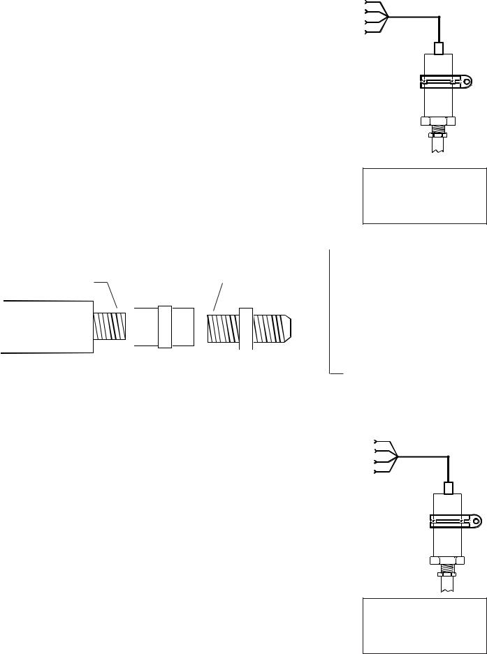
D. Fuel Pressure Transducer Installation:
Find a convenient location on the firewall or a bracket
and mount the pressure transducer with the clamp provided. The fuel pressure line does not have to be
routed into the cabin area although you will need access on the cabin side of the firewall to tighten the pressure
transducer clamp nut. Do not mount the pressure transducer to an engine baffle
or directly onto the engine with the transducer supported by an adapter or fitting. Vibration can cause the adapter to break, resulting in loss of engine fuel. The pressure transducer is equipped with a 1/8" NPT male port. This port can be adapted to
any fuel pressure line. Use only a flexible hose and fittings suitable for aircraft use. Route a flexible fuel pressure line from the primary fuel pressure pick up point to the pressure transducer and tighten all fittings. Do not use the case of the pressure transducer to tighten the pressure fittings. Maintain any restrictive
orifice currently in the system.
* Some fittings you may want to consider using are listed above.
17

E. Airspeed Transducer Installation:
Mount the PT-05Diff Pressure Transducer on the inside firewall or in the equipment bay under the aircraft instrument panel. Use the holes in the bottom plate to mount the PT-05Diff. Only two mounting holes are required.
PRESS

 GyroPitotVacuumLine
Line
 VAC
VAC
Connect the aircraft pitot (airspeed) line to the port
tagged "Press" on the PT05Diff. Connect the aircraft static pressure line to the port tagged "Vac" on
the PT-05Diff. Be sure these lines are tight. The ports are 1/4" flare union. Care should be taken not to put excess pressure on the flexible lines. Make sure the flexible lines do not kink.
F. Altitude Transducer Installation:
Mount the PT-30Alt Altitude Transducer on the inside firewall or in the equipment bay under the aircraft instrument panel. Use the holes in the bottom plate to mount the PT-30Alt. Only two mounting holes are required.
 .170" ID Flexible Tube
AircraftStaticLine
Connect the aircraft static line to the port
on the PT30Alt. Be sure this line is tight. The port is a 1/
4" flare union. Care should be taken not to put excess pressure on the flexible line. Make sure the flexible line does not kink.
G. Other Pressure Transducer Installations:
Other pressure transducers should be mounted in the aircraft in the same manner as the Gyro Vacuum Transducer or the Oil and Fuel Pressure Transducers, as appropriate. Note: Any unused + or - pressure inputs must be wired to a ground pin on the EDC 37-pin connector.
18

2.8 Install the Interface Circuit for Annunciators:
Any Temperature or Resistive Fuel Level channel on the EDC may be used to monitor the state of a switch, relay or output from a device. This output can be used to trigger a light (annunciator) on the MVP. Annunciator lights such as Canopy Latch, Baggage Door, Deice, Pitot Heat, Fire, etc. can be displayed on the Main or System screen on the MVP.
To monitor a voltage, a VI-221 (Voltage Interface Unit) will be required. This consists of a 221K ohm resistor heat shrunk between two wires with a D-Sub pin crimped on one end. The following methods may be used to interface an EDC channel (using a VI-221) to a switch, relay or device:
A. Monitoring a Signal That Switches Between Any Voltage and Ground:
Device, Switch or Relay |
|
|
Bus or any Voltage |
|
EDC |
VI-221 |
Temp or Resistive Fuel |
|
|
|
Level Channel. |
Load |
|
|
B. Monitoring a Signal that is Switched to Ground:
|
|
|
|
|
|
|
|
|
Bus |
|
|
|
|
|
|
|
|
|||||
|
|
|
|
|
|
|
|
|||||||||||||||
|
|
|
|
|
|
|
|
|
|
|
|
|
|
|
|
|
|
|
|
|
|
|
If a Load does not exist, |
|
|
|
|
|
|||||||||||||||||
|
|
|
|
|
||||||||||||||||||
an additional VI-221 |
221VI- |
|
||||||||||||||||||||
must be placed in the |
|
|
|
|
|
|
|
|
||||||||||||||
|
|
|
|
|
|
|
|
|||||||||||||||
circuit as shown. This |
|
|
|
|
|
|
|
|
||||||||||||||
provides a pullup for the |
|
|
|
|
||||||||||||||||||
|
|
|||||||||||||||||||||
switch. |
|
|
|
|
|
|
|
|
||||||||||||||
|
|
|
|
|
|
|
|
|
|
|
|
|
|
|
|
|
|
|
|
|
|
|
Load
Light, Horn, etc.
EDC
VI-221 Temp or Resistive Fuel Level Channel.
Device, Switch or Relay
19

2.9 Install the Interface Circuit for Flap and Trim Pots (OEM / Experimental):
Elevator, Aileron and Rudder trim (as well as Flap position) can be monitored and displayed on the MVP. In most cases the position of these surfaces are monitored using a mechanical 5K ohm pot. The following circuit may be used to interface with a 1K to 100K pot.
4.99K, 1%, 1/4W Resistor
Bus 


|
|
|
|
|
|
|
|
1K to |
|
|
|
|
|
EDC |
|
|
|
|
VI-221 |
|
Temp or Resistive Fuel |
||
100K |
|
|
|
|
|||
|
|
Mechanical |
Level Channel. |
||||
|
|
|
|
||||
|
|
|
|
|
|||
|
|
|
|
Pot |
|
||
|
|
|
|||||
|
|
|
|
|
|
|
|
2.10 Install the Interface Circuit for the Gear Position, Unsafe Indicator and Gear Warning:
The Gear Position and Unsafe Indicator shown on the MVP System Screen is intended as a backup to the aircraft’s existing system. The Gear Warning operates off the Gear Position, Unsafe Indicator, Airspeed and Manifold Pressure. The Gear Warning provides a voice warning to reduce the possibility of gear up landings. Voice warnings are NOT available for certified aircraft at this time.
Unsafe Indicator: Operates from an unsafe signal from the aircraft. Displays as either Red or Off on the MVP. The EDC interface circuit is shown below. The Unsafe Indicator is REQUIRED with any landing gear options listed below and requires one EDC input.
Landing Gear Position: There are three options for interfacing the EDC to the aircraft’s gear system, all of the options below require the Unsafe Indicator (see above).
Option 1: Connect the EDC to the aircraft’s Right, Left and Nose Gear green down lights. The state of each gear will be displayed independently on the MVP. Select Gear Left, RT and Nose for the probes in Configuration Screen #1. This option requires three EDC inputs. The EDC interface circuit is shown below.
Option 2: Connect the EDC to the aircraft’s Nose Gear green down light. The state of all three gears will be displayed on the MVP based on the Nose Gear’s state. Select “Gear All” for the probe in Configuration Screen #1. This option requires one EDC input. The EDC interface circuit is shown below.
Option 3: Use this option to display only the Left and Right Main Gears (no Nose Gear) from a single input. Connect the Left or Right Main Gear to the EDC as shown below. Select “Gear Main” for the probe in Configuration Screen #1. This option requires one EDC input. The EDC interface circuit is shown below.
Note: When setting colors, use Green for down and White for up. Red will cause an error.
20

Gear Up Warning: To provide a Gear Warning the MVP must monitor Gear Position, Airspeed and Manifold pressure. A voice warning (for experimental aircraft only) is activated on the following logic:
(Any Gear is up -OR- the Unsafe Indicator is on) -AND- Airspeed is less than a set value - AND- Manifold Pressure is less than a set value.
Note: See the “Aircraft Number, Gear Warning and TAS Setup” screen to set values.
Gear and Unsafe Interface Circuit
TapintotheswitchedsideoftheLight
EDC
VI-221 Temp or Resistive Fuel
Level Channel.
 GearorUnsafeLight
2.11 Install the CO Detector, G-Sensor and/or Other Available MVP Options:
The CO Guardian Remote Mounted CO Detector, G-Sensor and other MVP options listed on EI’s price sheet are providedwiththereowninstallationinstructions. Theseitemsshouldbeinstalledandwiredinaccordancewiththe accompanying instructions. Note: The CO Detector connects to Port 3 Input on the MVP.
2.12 Install the Shunt:
An external shunt is a strip of metal, usually mounted on a bakelite base. This metal is made of special alloys to produce a very small, precise signal when current passes through it. It is not affected by temperature changes. If your aircraft currently has an external shunt you can calibrate your MVP to that shunt. The MVP can be calibrated to match any shunt on the market.
A. Determine How the Shunt will be
Installed |
in the Aircraft’s Electri- |
|
|
Installation Method |
Advantages |
Disadvantages |
|
cal System: |
|
|
|
|
|
|
|
|
|
|
Battery Lead: |
1. Shows load current on the |
1. Cannot show load current during |
||
|
|
|
|
|
|||
|
|
|
|
|
|
ground (engine off) and during |
flight or when the engine is running. |
There are two common methods of |
|
|
|
an alternator failure. |
|
||
installing a shunt in an aircraft. |
One |
|
|
|
2. All Warning Lights are |
|
|
method is with the shunt in the alterna- |
|
|
|
operational. |
|
||
tor lead. |
The other method is with the |
|
|
Alternator Lead: |
1. Shows load current during |
1. Cannot show load current when |
|
shunt located in the battery lead. |
The S- |
|
|
|
flight or when the engine is |
the engine is off or during an |
|
|
|
|
running. |
alternator failure. |
|||
50 shunt that comes with the MVP-50 |
|
|
|
2. All Warning Lights are |
|
||
package may be installed using either |
|
|
|
|
|||
|
|
|
operational. |
S0224921 |
|||
method. |
The advantages and disadvan- |
|
|
|
|
|
|
|
|
|
|
||||
tages of each method are listed below.
There are few disadvantages with either method. Although EI’s test pilot has a slight preference for
21

the alternator lead when using the MVP, ease of installation should be the determining factor in this installation. If more than one shunt is required, a second shunt can be installed through a FM-VA-M- (50 or 300) Functional Module. The Functional Modules come with their own installation instructions.
B. Install the External Shunt:
The external shunt should be installed in an appropriate location that minimizes the routing of main cables (refer to figure 1 or 2 as appropriate for your installation). It should also be mounted in a location where inadvertent damage cannot occur. If the shunt can be accessed easily, it should be covered. When mounting the shunt, use self-locking or safetywired nuts.
Shunt
The signal wires from the shunt to the EDC must be fused a short distance after they leave the shunt. If this is a new installation, install two in-line one-amp fuses, one in each of the signal lines from the shunt to the EDC Amp Input.
Note: If you are replacing an existing ammeter, the shunt may already be mounted in the aircraft. If you already have a shunt installed and know the value of the existing shunt, the MVP can be calibrated to that shunt.
Figure 1: External Shunt Installed in the Battery Lead
To Voltage Regulator
Master Switch
Contactor
Batt.
Starter Solenoid
To Starter
F B G
Alternator
This line may be connected currently to the Master Switch Contactor or the Starter Solenoid. In either case it should be rerouted to the Bus or + side of the Shunt.
- +
External Shunt
B U S
Note: The External Shunt should not be installed in series with the starting current.
This is the main lead going to the Bus. It may come from the Master Switch Contactor or the Starter Solenoid.
22
 Loading...