

Page 1
Installation Manual
Signature________________________
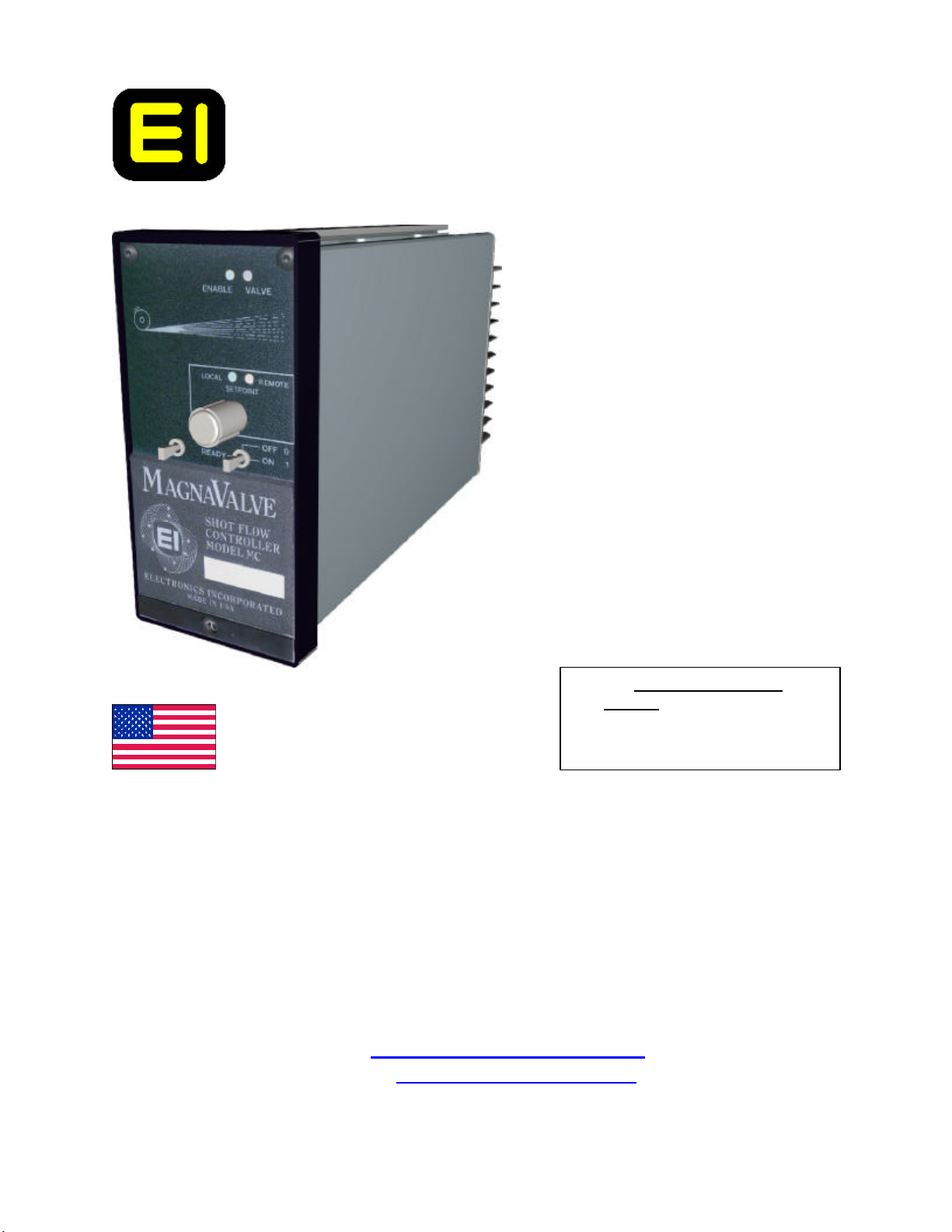
Model MC Shot Flow Controller
Made In America
Electronics Incorporated
56790 Magnetic Drive
Mishawaka, IN 46545
1-800-832-5653 (Toll Free)
1-574-256-5001 (Phone)
1-574-256-5222 (Fax)
E-mail: shotpeener@shotpeener.com
Website: http://www.shotpeener.com
Doc Title MC Installation Manual
P/N: 999235.C
Date: ___________________________
H:\MANUALS\IM0049C.DOC Installation Manual Model MC Shot Flow Controller 1 of 12
Page 2

TABLE OF CONTENTS
1.PRODUCT DESCRIPTION..........................................................2
2.THEORY OF OPERATION..........................................................2
3.PRELIMINARY ADJUSTMENTS................................................2
4.OPERATION ................................................................................2
5.SPARE PARTS LIST.....................................................................2
6.WARRANTY ................................................................................3
7.SERVICE/START-UP ASSISTANCE..........................................3
8.UPGRADES - REVISIONS ..........................................................3
9.TROUBLESHOOTING GUIDE....................................................3
FIGURE 1. FRONT PANEL (Operator Controls)...........................6
FIGURE 2. FRONT PANEL (Technician Adjustments) ...................7
FIGURE 3. FRONT PANEL (Factory Settings)...............................8
FIGURE 4. TEST SOCKET PIN ASSIGNMENTS.........................9
FIGURE 5. WIRING CONNECTIONS........................................10
FIGURE 6. SPECIFICATIONS.....................................................10
10. How To Return Controllers For repair………………………12
H:\MANUALS\IM0049C.DOC Installation Manual Model MC Shot Flow Controller 2 of 12
Page 3

1. PRODUCT DESCRIPTION
The Model MC Shot Flow Controller will control the rate of flow of steel shot passing through a special
normally closed magnetic valve called a MagnaValve. A setpoint knob or an external 0-10 Volt dc
command signal is used to set the shot flow rate.
2. THEORY OF OPERATION
The MagnaValve is a normally closed magnetically operated valve with no moving parts. An
electromagnet coil inside of the valve is used to cancel the permanent magnet field and allow shot to
flow. The MC controller supplies the voltage to the MagnaValve and provides 0-100% regulation of
flow rate.
3. PRELIMINARY ADJUSTMENTS
(For location of adjustments see (Figure-Item) as noted.)
Maximum Output Limit:
On wheel type blast machines it is usually desirable to limit the maximum motor amps by restricting the
maximum shot flow rate to the wheel. The maximum output signal from the MC controller may be
restricted to prevent excessive flow rates that might overload the wheel motor. Remove the front panel
lower cover plate for access to the adjustments. Turn the maximum output trimpot to the counterclockwise position for minimum range. Turn the setpoint knob to full clockwise position. Enable the
controller. Turn the maximum output trimpot until the desired maximum flow rate is achieved.
4. OPERATION
To energize the MagnaValve the MC controller must be enabled. This can be done with the mode
switch (1-5) by placing it into the ON position or by placing the mode switch into the READY position
and applying a 120 Vac to the ENABLE screw terminal #3. The LED labeled "Enable" will indicate
that the enable signal is present (1-1).
The flow rate command can come from the front panel local setpoint knob or a remote 0-10 Vdc
command. The LED's (1 - 3) and (1 - 4) indicates which command is active. Switch (2 - 1) is used to
select local or remote command. The remote analog command is applied at screw terminal #10 with
common at screw terminal #9.
A red LED (1 - 2) is provided to indicate status of the output signal to the MagnaValve. It will be off
for no-flow, blinking for low flow rates and constantly on for maximum flow rate. The signal is a fixed
frequency variable duty cycle (PWM) type of output. Longer "on" times provide larger flow rates.
H:\MANUALS\IM0049C.DOC Installation Manual Model MC Shot Flow Controller 3 of 12
Page 4

5. SPARE PARTS LIST
For each machine, at least one of each of the following is recommended:
a. Spare MC Control
c. Spare MagnaValve
6. WARRANTY
Electronics Incorporated warrants this product to be free from defect in material and workmanship for a
period of two years from date of shipment. Defective units must be returned to Electronics
Incorporated with shipping costs prepaid. Call for a Return Authorization Number and shipping
instructions. Electronics Incorporated will repair or replace defective unit at its option. No
consequential liability is assumed. No other warranty, including merchantability or fitness for purpose,
applies or is expressed or implied.
Warranty work is only available at the factory. On-site service or start-up assistance is available at
extra cost to customer. See Section VII.
Caution: Any customer attempts to modify or repair the product during the warranty period will
terminate the warranty. Standard technician labor rates will be quoted prior to repair work.
7. SERVICE/START-UP ASSISTANCE
Service is an option available at the time of original purchase or as required by customer. A purchase
order is required prior to making a service call.
8. UPGRADES - REVISIONS
Design improvements are constantly being made to our products. Please contact Electronics
Incorporated for details. When ordering spare units, please refer to model number and serial number of
each unit.
9. TROUBLESHOOTING GUIDE (WHEEL TYPE BLAST MACHINES)
1. SYMPTOM: Problems with stability
If the machine uses a variable speed drive, check it for stability or bypass it with a conventional
motor starter.
The instability may be caused by flooding/choking the wheel or trying to flow more shot than the
capability of the wheel. Check for obstructions or restrictions or unnecessary bends in the flow path.
Worn blades or damaged control cages will not pass as much shot as new blades, therefore as blades
wear the maximum shot flow rate is reduced.
H:\MANUALS\IM0049C.DOC Installation Manual Model MC Shot Flow Controller 4 of 12
Page 5

Use a clamp-on type ammeter to verify panel meter ammeter reading. Occasionally, the
number of wraps of wire around the panel meter current transformer is incorrect, or the current
transformer ratio is not correct for the load amperage and meter range. Also, have someone verify that
the amperage target is correct. Usually, the Almen strip is used as primary process verification and
ammeter readings are subordinate. If Almen strip arc height, percentage of piece part coverage, and
process time are acceptable, what should the wheel amperage be?
Shot condition is very important. Unclean shot, due to oil, water or dust, can cause erratic flow
performance. The dust can be generated by shot deterioration, or by abrasion of the parts being
peened or the cabinet or tooling. The dust will tend to cake and clog the flow. Under severe
conditions, the MagnaValve may become completely blocked.
2. SYMPTOM: Setpoint does not control flow rate.
a. Green LED (1 - 3) "Local" or Yellow LED (1 - 4) "Remote" should be on for local
setpoint knob operation.
b. Enable signal must be present (Screw Terminal #3). Also, the "Enable" LED must be
lighted (1 -1).
c. MagnaValves operate using a magnetic field and have no moving parts. High differential air
pressure caused by wheel rotation causes suction, which may suck shot through the valve. This
symptom is characterized by having shot flowing when valve is off (red valve LED = off). It may be
necessary to provide an aspiration air inlet below the MagnaValve. Contact factory for advice.
d. MagnaValve valve driver module may be defective. The valve driver module is factory set
and is used to regulate the precise amount of current necessary to cancel the permanent magnet field in
the MagnaValve. If this module fails there may be no current or excessive current. The correct output
current setting is listed on the valve driver module. Check the valve current with an ammeter in series
with wire lead from the controller (screw terminal #7) to the valve driver module (screw terminal #1).
The dc current should be within 10% of the listed value. If it is not, try to adjust it using the trimpot
located on the valve driver module. If this does not change the MagnaValve current then replace the
valve driver module. The new valve driver module must be set to the value listed on the old valve driver
module to properly operate. Contact factory for assistance.
3. SYMPTOM: Cannot achieve any flow, or flow rate is very low.
a. Enable light must be on (1 - 2).
b. Green LED for "Local" or Yellow LED for "Remote" setpoint must be on.
c. Red LED "Valve" should be bright and blinking or constantly on. An internal circuit breaker
has tripped. If it is dim, check for short circuit valve wiring at Terminals #7 and #8. To reset the circuit
breaker, remove and re-apply the Enable signal.
d. Check red LED at MagnaValve junction box. If it is not "on" check for a wiring problem. If
it is "on" check the current going to the valve driver module and see that it matches the label on the valve
driver module.
e. Check for contamination in or above MagnaValve, especially check for water, oil, or dust
mixture in the shot.
f. MagnaValve or valve driver module may be defective. To check, remove valve from machine
(keep wires attached). Enable the output and get red LED valve "on" at 100% duty cycle. When
H:\MANUALS\IM0049C.DOC Installation Manual Model MC Shot Flow Controller 5 of 12
Page 6

Valve LED is on, the magnetic field should be perfectly canceled. No shot should stick inside the
MagnaValve. If any shot sticks to the valve, then either the valve driver module or the MagnaValve is
defective. Measure the dc current going to the valve driver module in the red wire. This should be
approximately 0.5 to 0.7 Amps dc. Compare your measurement to the value written on the label of the
valve driver module. If your reading is not within 10%, then the valve driver is defective or not adjusted
properly. Try adjusting the drive current to the listed value. If the current does not change with
adjustment then the valve driver module is defective and must be replaced. Be sure the replacement
valve driver is pre-calibrated to the same value as the original module. If your reading is within 10% of
the original valve driver calibration, the valve driver module is OK but the valve is defective.
4. SYMPTOM: Often have high flow or flow continues when setpoint is reduced or enable is turned
off.
Valve is leaking shot.
a. This is usually caused by pressure difference across the valve. Some wheels at some speeds
and flow rates tend to provide a large vacuum and this may suck shot through the MagnaValve. Relieve
this negative pressure by providing a hole (1/2" diameter) in the hose immediately below the
MagnaValve. This allows aspiration air to help convey the shot to the wheel inlet.
5. SYMPTOM: Shot flow rate is erratic or unstable.
a. Check shot for cleanliness.
b. Check shot for cleanliness.
c. Check shot for cleanliness.
d. Check valve driver module and MagnaValve.
e. Call the factory for advice.
NOTE: This category is the most challenging to trouble shoot. We have found that shot
cleanliness and foreign objects are usually responsible. Items, such as: wire (from identification
tags), welding rod, nuts-bolts from machine or screen separator, masking tape, razor blades,
milk cartons, cigarette butts, etc. seem to find their way into the MagnaValve.
FIGURE 1. FRONT PANEL - Operator Controls
ITEM DESCRIPTION
1. ENABLE - This LED indicator will be on if the mode switch is "On" or in the "Ready"
position and customer applies 120 Vac to control enable screw terminal #3.
2. VALVE - This LED indicator shows power output to the MagnaValve at variable duty cycle.
(When this LED is off, the permanent magnet in the MagnaValve holds the shot and there is no
flow. When this LED is on, the MagnaValve solenoid cancels the permanent magnet and you
have maximum shot flow. When this LED is blinking, the shot flow rate is being regulated.)
3. LOCAL - This LED indicator shows that the control is in the "Local Mode" and the setpoint
knob below it will command the shot flow rate.
H:\MANUALS\IM0049C.DOC Installation Manual Model MC Shot Flow Controller 6 of 12
Page 7

7 6 5 4 3 2 1
4. REMOTE - This LED indicator shows that the control is in the "Remote Mode" and a remote
analog 0-10 Vdc command is expected at screw terminal #10.
5. SETPOINT KNOB - This knob will set the desired shot flow rate when the control is in the
"Local Mode".
6. MODE SWITCH - This switch determines the controller mode of operation.
Right = Forced On
Middle = Forced Off
Left = Ready (waiting for "Enable" signal from machine at terminal #3)
7. DECAL - Space is provided for the customer to make additional notations.
FIGURE 1. FRONT PANEL - Operator Controls
FIGURE 2. FRONT PANEL - Technician Adjustments
Item Description
1. SETPOINT LOCAL/REMOTE - This switch will select whether the setpoint
command comes from the front panel knob or from an external remote analog 0-10 Vdc
command.
H:\MANUALS\IM0049C.DOC Installation Manual Model MC Shot Flow Controller 7 of 12
Page 8

2. MAXIMUM OUTPUT LIMIT - This adjustment sets the maximum output level to
1
the MagnaValve to prevent the operator from overloading the wheel motor. This limit applies to
both the setpoint knob and the external remote command, if used.
2
FIGURE 2. FRONT PANEL - Technician Adjustments
FIGURE 3. FRONT PANEL - Factory Settings
Item Description
1. FACTORY FREQUENCY - Factory setting of output signal frequency to 8 Hertz.
DO NOT RE-ADJUST.
2. FACTORY BIAS - Factory setting of internal triangle generator signal (calibrates the
low output level). DO NOT RE-ADJUST.
3. FACTORY AMPLITUDE - Factory setting of internal triangle generator signal
(calibrates high duty cycle output level for 10 Vdc command). DO NOT RE-ADJUST.
H:\MANUALS\IM0049C.DOC Installation Manual Model MC Shot Flow Controller 8 of 12
Page 9

1 3
2
FIGURE 3. FRONT PANEL - Factory Settings
FIGURE 4. TEST SOCKET PIN ASSIGNMENT
Test Point Socket Number
1. (-) 5 Volt dc reference voltage
2. (+) 5 Volt dc reference voltage
3. (+) 5 Volt dc for digital display
4.
5.
6.
7.
8. "ON" logic signal from enable circuit
9.
TP-8 10. Logic (PWM) pulse width modulation (after circuit breaker)
11.
12. +10 Vdc reference excitation voltage
TP-5 13. Output of triangle generator
14. Common 0 Vdc
15. (-) 12 Vdc excitation output
16. (+) 12 Vdc excitation output
H:\MANUALS\IM0049C.DOC Installation Manual Model MC Shot Flow Controller 9 of 12
Page 10

123456789
10
MC CONTROLLER BACK VIEW
1 AMP
END VIEW (with Valve Driver removed)
FIGURE 5. WIRING CONNECTIONS
1. Power Neutral (120 Vac)
2. Power Hot (120 Vac)
3. Enable Input (120 Vac)
4. (+) 10 Vdc Reference Output
5. (+) 12 Vdc Excitation Output
6. (-) 12 Vdc Excitation Output
7. (+) MagnaValve Output
8. (-) MagnaValve Output
9. Common - Shield
10. Remote Set Point Input (0-10 Vdc)
Green screw on back panel is for earth - chassis grounding.
Red
Black
Orange
Brown
BACK OF VALVE DRIVER ( VD12 )
GROUND
NEUTRAL
CABLE TO MAGNAVALVE:
16 AWG WIRE IN
CONDUIT OR SEAL-TITE
AC HOT
(120VAC)
GREEN
WHITE
BLACK
FUSE
EARTH
GROUND
(SHIELD)
TABLE 6. SPECIFICATIONS
Power: 120 Vac, 50/60 Hertz, 50VA
Inputs: Remote Command Set Point (0-10 Vdc)
Enable (92 - 120 Vac)
Outputs: Valve Power 50 Vdc PWM at 10 Hertz
H:\MANUALS\IM0049C.DOC Installation Manual Model MC Shot Flow Controller 10 of 12
Page 11

Excitation Voltage +/- 12 Vdc @ 100 mAmp
Reference Voltage + 10.00 Vdc @ 10 mAmp
Weight: 4 Lbs. (1.8 Kg)
Modify Input Range
The standard input range for remote command is 0 -10 Vdc. Some applications have only a 0 - 5 Vdc
signal available from the PLC . The MC controller can accommodate this range of signal by making the
following adjustments.
1. This procedure requires the controller valve output to be exercised. If valve operation would cause a
problem flooding the wheel then either remove the wires to the MagnaValve or close the service slide
gate above the MagnaValve. The wheel does not need to be rotating for this conversion procedure.
2. Use a “battery box” or other suitable source of 5 Vdc applied to the remote command input terminal
(#10) and apply 5.0 Vdc to the controller (terminal #9 is circuit common).
3. Place the mode switch in the “on” position. The red LED for “valve” should be blinking.
4. Adjust the “Amplitude” control until the LED is constantly “on” for 100% duty cycle.
5. Apply 0 Vdc to the input and verify that the red LED stays off. If necessary, adjust the “Bias”
control.
6. The red LED should now operate as follows:
a. 0.0 Vdc input = red LED off
b. 0.1 Vdc = red LED blinking at low duty cycle
c. 4.9 Vdc = red LED blinking at high duty cycle
d. 5.0 Vdc = red LED constantly on
7. CAUTION: The front panel set pot on the MC controller will now only function over half of its
range. The full output will be achieved at 5-turns instead of the full range 10-turns of the set pot.
H:\MANUALS\IM0049C.DOC Installation Manual Model MC Shot Flow Controller 11 of 12
Page 12

Mishawaka, IN 46545
How To Return Controllers For Repair
2
Installed in panel. Turn “Off”
All power sources to controller
before going to step 2.
3
Remove Rails and Rail Mounting Screws.
Slide controller forwards.
5
Controller is ready to return.
4
6
Remove terminal blocks
and leave wires attached.
Slide Rails back on and install the
Rail Mounting Screws.
Call 1-574-256-5001 ask for a
Returns Goods (RG) Number (#)
Ship controller with RG # to:
Electronics Incorporated
56790 Magnetic Drive
H:\MANUALS\IM0049C.DOC Installation Manual Model MC Shot Flow Controller 12 of 12
******END OF MANUAL********
 Loading...