

Page 1

Instruction Manual
Low Profile MagnaValves
Electronics Inc.
56790 Magnetic Drive
Mishawaka, Indiana 46545
1-800-832-5653 (Toll Free)
Phone: 1-574-256-5001
Fax: 1-574-256-5222
E-mail: sales@electronics-inc.com
Website: www.electronics-inc.com
Model LP-24 and Model VLP-24
IM:0083 Revision: B Date: 11/1/2012
Made in the USA
Page 2
y
(
)
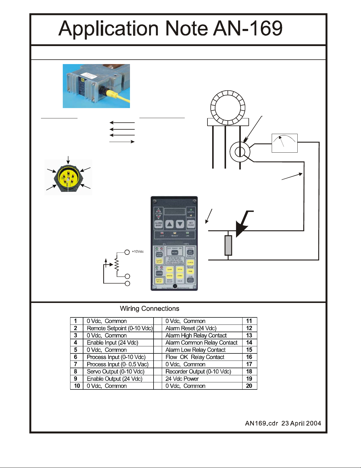
WIRE CONNECTIONS FOR VLP-24 OR LP-24 TO AN AC-24 A MPERA GE CONTR OLLER
NOTE : The valve must be loc ate d as close to the wheel
as possible for bes t servo cont r ol stabili t
5 feet or close r
Customer CT
100:5 etc.
PANEL METER
(IF USED)
0
VLP-24/LP-24
4) Orange 0-10 Vdc input
6) Blue 24 Vdc Enable
2) Red 24 Vdc Supply
5) Black 0 Vdc Common
WHEEL
MOTOR
AC-24 Controll er
8) Servo Out
9) Valve Enable
19) 24 Vdc Supply
20) 0 Vdc Common
3
1. WHITE
4
5
6
NOTE: The Controller's Full Scale display (typical
100.0) must match the customer's current
transformer rating (typical 100:5 ratio). Adjust the
control display range to match the actual
transform er ratio. See instru ction manual.
2
2. RED
3. GREEN
4. ORANGE
5. BLACK
1
6. BLUE
0-5 amps
L3
L2
L1
Use 12 AWG wire for current loop. Use
10 AWG or larger for runs over 15 ft.
AC-24 Rear Terminal
Current Shunt
.05 ohm 5 watt.
P/N 999200
Included with
controller.
7
.
100
(0-5A)
*
Remote setpoint can come
from customer potentiometer
or 0-10 Vdc signal. Also see
model Pot-24 rem ote pot.
.05 Ohm shunt
.05 Ohm shunt
VLP-24 Or ange
VLP-24 Blu e +24Vdc to VLP-24 RED
Note: Connect power supply directly to the MagnaValve first and then run power back to the control using minimum 16 AWG
wire size t o prevent (high curr ent ) voltage drops. Pow er supply should be re gulated and rated at 50VA per valve.
CW
2
0 Vdc
common
5
Alternate: Long length of curren t loop may cause
inaccuracy. To keep the 0-5 Amp current loop sh ort
you may place the .05 ohm shunt at the transformer
termina ls and run 18 AWG shielded ca bl e f rom shunt
to control.
0Vdc to VLP-24 BLACK
www.magnavalve.com
2
Page 3

Diagnostic LED’s
VALVE ON – When this LED is on or blinking, the electromagnet is receiving power. When the LED
is off, the permanent magnets will hold or block the shot flow. When the LED is on, but not blinking,
the valve flow rate is at full capacity. When the LED is blinking, the electromagnet is regulating the
shot flow.
Vin > 0.25 Vdc- This LED indicates that the valve is receiving an analog signal input greater than
0.25 Vdc. When this LED is off there is no media flow allowed. The input signal range is 0-10 Vdc. At
10 Vdc the valve will “open” to full capacity, which is usually 10% to 50% higher than the calibrated
range. The relationship between the 0-10 Vdc input signal and actual flow rate is nonlinear. The output signal 0-10 Vdc signal is linear and this makes accurate regulation by the AC-24 control possible.
24Vdc ENABLE – This LED indicates that the valve is receiving a 24 Vdc Enable signal. When this
LED is off, the valve is inhibited, and no shot will flow. This feature is an on-off action so there is no
need to disable or remove the 0-10 Vdc input signal.
24 Vdc Power – This LED indicates that 24 Vdc is available to operate the electromagnets for media flow. It should always be available and able to supply 2 Amps. If the LED is blinking, the supply
is above the recommended operating range +/- 2VDC (22-26VDC). If the LED is OFF, then the supply is below the recommended range. If that condition occurs, please call for technical support.
All of the LED’s must be on in order to have media flow.
3
Page 4

This manual will explain how to replace the mechanical media (grit) valve on a wheel type blast
cleaning machine with the new MagnaValve automatic media regulator. The two most prominent
reasons for this type of upgrade are:
a) to eliminate maintenance required for the air cylinder that operates the mechanical valve
b) to provide an automatic alarm to alert the operator to replenish the shot/grit supply
The machine used for illustration in this manual is a RotoPeen system from Pangborn Corporation
modified to shot blast clean 20 foot lengths of round pipe. It is a single wheel, 20 horsepower, passthru cabinet design as shown in Fig. 1 below.
Fig. 1
The following text will describe each of the remaining photos in three sections, before, during and
after the installation of the MagnaValve. The entire project required less than one day for the conversion.
Note: To operate properly and prevent damage to the MagnaValve, always supply the full flow capacity of the valve. For example, a VLP will flow 1000lbs/min. While only 400lbs maximum is required for the application, the MagnaValve must be supplied the full 1000lbs to operate correctly. If
an amount less than 1000lbs is supplied, the shot travels through the valve at a high velocity, and
can damage the valve.
4
Page 5
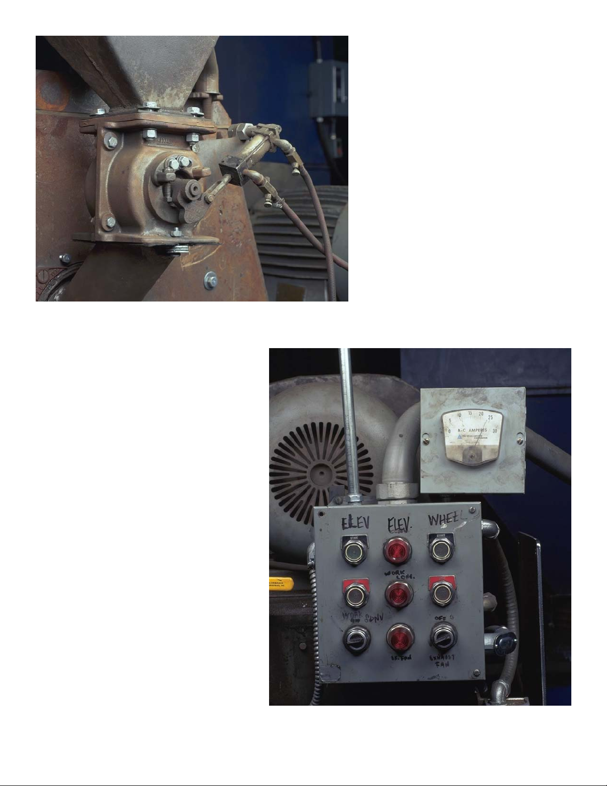
Fig. 2 An air cylinder was used to
open and close the original mechanical
valve as shown. This air cylinder was
controlled by a manually operated 2way air valve. The air cylinder moves
the mechanical valve from its closed to
open position. The amount of opening
was pre-set by the operator by adjusting a nut on the linkage of the air cylinder to limit the stroke.
Fig. 2
Fig. 3 This figure shows an ammeter
reading of approximately 8 amps, the
no-load or no shot flow condition. A
conventional panel ammeter (0-30
Amps) was used to indicate motor
amps and relative shot flow rate. It is
not uncommon for these meters to be
inaccurate because metallic dust collects inside the meter movement mechanism. This prevents the meter from
displaying the proper amperage.
Fig. 3
5
Page 6

Fig. 4 This figure shows the original
operating amperage level, in this case
approximately 24 amps. Tests indicated a 4 amp error.
Fig. 4
Fig. 5 The first step in removing the
old mechanical valve is to remove the
feed spout going to the wheel inlet.
First, remove the four bolts attaching
the feed spout to the bottom of the mechanical valve.
Caution: Be sure the machine is
properly locked out. Follow all safety
precautions and instructions shown on
the machine or in the owner’s manual.
Fig. 5
6
Page 7

Fig. 6 Some machines will have a slide gate
or maintenance gate located above the mechanical valve. This should be closed to allow
removal of the mechanical valve without
draining the shot from the hopper. If the machine does not have a slide gate (this machine did not), you must drain the hopper.
Drain the shot from the hopper using a hose
or chute to guide the shot into a drum or receptacle.
Fig. 6
Fig. 7 Next, remove air hoses
from air cylinder and terminate
the air supply line coming from
the air compressor. With the
slide gate closed (if available) or
with the hopper empty, loosen
the bolts from the top of the mechanical.
Fig. 7
7
Page 8

Fig. 8 Once the bolts are removed,
remove the valve from the machine.
Be careful. The valve is heavy and
may contain some shot that may spill
upon removal.
Fig. 8
Fig. 9 Special adapter plates can be
fabricated that will compensate for the
bolt hole locations and vertical spacing
needed by the MagnaValve.
Fig. 9
8
Page 9

Fig. 10 The adapter plates should be
installed onto the MagnaValve and the
assembly installed as a single unit. The
entire MagnaValve assembly can be
temporarily positioned and held into
place by using vise-grip or similar pliers
and then the bolts can be installed and
tightened.
Note: Adding a nonmetallic 1” spacer
above and below the MagnaValve will
improve MagnaValve performance.
Fig. 10
Fig. 11 The feed spout can now be rein-
stalled easily, since it bolts directly to the
adapter plate. Be sure to use a rubber gasket between the adaptor plate and the feed
spout. Do not use silicon or any other adhesive that will make it difficult to remove the
valve for inspection.
Fig. 11
9
Page 10

Fig. 12
Fig. 13 A new electrical panel was
used in this installation and was
mounted to a rigid plate prior to performing the wiring. Some installations
have adequate room in the existing
electrical panel, however, be sure that
the electrical panel is suitable (dust
tight, proper location for operator viewing, and well ventilated to prevent temperatures above 140 degrees F) for the
enviroment.
Fig. 12 The cable fastens to the mating connector. The cable should be routed in either
flexible or rigid conduit. In some installations
where the conduit for the air cylinder control
solenoid is nearby it is possible to reuse the
conduit for the MagnaValve cable.
Fig. 14
Fig. 13
Fig. 14 This is a rear view of the panel amme-
ter showing the connections to the meter lugs
coming from the current transformer secondary. Remove one of the meter wires to allow
installation of a wiring loop to the current shunt
mounted on the rear of the AC-24 Controller.
10
Page 11

Fig. 15 Attach the loose current transformer wire to one of the AC-24 controller shunt wires and attach the other
AC-24 controller shunt wire to the meter lug. This procedure allows the AC24 controller shunt to be in series with
the existing panel meter so that both of
them receive the (transformed) motor
current (0-5 Amps). If the panel meter
is to be eliminated then connect the
two current transformer output wires
directly to the AC-24 controller shunt.
Fig. 15
Fig. 16 Apply control power to the circuit.
Caution: Be sure all wiring has been
properly completed and that no shock
hazard exists. The AC-24 controller is
factory set to display 100.0 Amps full
scale when connected to a 100:5 ratio
current transformer. The display range
can be verified by pressing Coarse Display Range.
100.0
Fig. 16
11
Page 12

30.0
Fig. 17 Since this application uses a 30:5 ratio current transformer the AC-24 controller must be adjusted to read 30.0 full scale. Press and hold the
Coarse Display Range and Down arrow until 30.0 is
displayed. For finer adjustment use the Fine Display Range.
Fig. 17
Fig. 18 Start the wheel motor and
place a clamp-on type ammeter on
the motor leads to confirm calibration
of both the panel ammeter and the
AC-24 controller display.
Note: The AC-24 controller zero and
span have been factory set. Minor
adjustments may be needed. Press
the Span button along with up/down
arrows to change value. Release the
Span Button to see new amperage
readings. Make the controller reading
match the clamp-on ammeter reading. Even though there is no shot
flow, ammeter readings will show the
no load or no flow rate values. Note
that the clamp-on ammeter and the
AC-24 Controller digital display show
the no load motor amperage to be
about 8.8 amps, while the panel meter shows over 9 amps.
Fig. 18
12
Page 13

The last step of the installation is to adjust the AC-24 controller to the same operating amperage noted before at the beginning of the installation, 24 amps. Push and hold the Setpoint and press the
Down arrow until the value 24.0 appears in the display. Release the keypad and notice that the display returns to show the no load amperage. Activate the MagnaValve, either by pressing the Mode
keypad to the on position or pressing the Mode keypad to the Ready position and activate the blast
machine automatic cycle. The green ON LED on the front of the AC-24 controller will come on and
the green VALVE ON LED on the valve will start to blink, indicating that the valve is receiving power
pulses to allow shot to flow. After a few seconds the motor current will rise to the setpoint value, in
this case 24.0 amps. It is normal for the digital display to vary by +/- 0.2 amps. If the variation is
greater than this refer to the installation manual for the AC-24 controller.
This installation also included an alarm horn and a highly visible pedestal mounted light stalk with
green indicator to indicate shot flow and a red blinking indicator to show an alarm condition (such as
low shot flow). The elapsed meter for “abrasive on” time was included to verify the increased
productivity and reduced downtime.
13
Page 14

Fig. 20 Once the final conveyor speed
and shot flow rate (motor amps) have
been determined, the standard Almen
strip (SAE specification J442) can be
used to check for proper operation.
The Almen strip, shown here, is mounted with four hold-down screws onto a
standard Almen holder that has been
welded into place on the pipe. This is
the industry standard test for the shot
peening and blast cleaning intensity.
Fig 20
The Almen test strip is blasted on one side only and then removed from the holder. Once released
from the hold-down screws the strip will curve.
Fig. 21 The amount of this curvature,
called arc height, is an indication of
the blast stream intensity and the value, as measured on a standard Almen gage, can be placed into a
standard SPC process control chart.
There are three strip thicknesses, low
intensity (N), medium intensity (A),
and high intensity (C). Most abrasive
blast cleaning is performed at high
intensity with the (C) strip.
An arc height of .005" to .007" was
found to be ideal for this blast cleaning application.
Fig 21
14
Page 15

The advantage of using the Almen strip method lies in the ability to detect the many changes that
can occur in a blast machine cleaning operation. Many quality departments are demanding real
time process control to satisfy customer requirements for documentation. Instead of relying upon
the operator’s judgment of cleanliness, the Almen strip method provides a scientific basis for qualifying the machine. The following are the changes that can be detected by the Almen method:
a. Wrong shot size added to machine (check the bag or drum for correct size)
b. Wrong shot size, dust collector not removing all small or broken shot
c. Wrong shot hardness (check the bag or drum for correct hardness)
d. Incomplete coverage, due to exposure time, shot flow rate adjustment, or improper targeting
e. Improper targeting caused by worn wheel blades or control cages out of adjustment
15
 Loading...