

Page 1

Instruction Manual
MagnaV alve Amperage Controller
Electronics Inc.
56790 Magnetic Drive
Mishawaka, Indiana 46545
1-800-832-5653 (Toll Free)
Phone: 1-574-256-5001
Fax: 1-574-256-5222
E-mail: sales@electronics-inc.com
Website: www.electronics-inc.com
Model AC-24 Control
IM:0078 Revision: D Date: 1/11/2008
Made in the USA
Page 2

Table of Contents
PRODUCT DESCRIPTION 3
THEORY OF OPERATION 3
LOCATION OF ADJUSTMENTS 3
PRELIMINARY ADJUSTMENTS 3
OPERATION 4
STABILITY ADJUSTMENT 6
MOTOR AMPS FULL SCALE DISPLAY 6
MOTOR AMPS CALIBRATION 7
WARRANTY 7
UPGRADES — REVISIONS 7
TROUBLE-SHOOTING GUIDE 7
EXAMPLES 9
CALCULATING FLOW RATE (Pounds per minute) 10
SPECIFICATIONS 11
WIRING CONNECTIONS 11
FIGURE 1: FRONT PANEL (Operator Controls) 12
FIGURE 2: FRONT PANEL (Technical Adjustments) 13
TABLES FOR CALCULATING FLOW IN POUNDS/MINUTE 14
TROUBLESHOOTING ASSISTANCE FORM 15
HOW TO RETURN CONTROLLERS FOR REPAIR 16
2
Page 3

1. PRODUCT DESCRIPTION
The Model AC-24 Amperage Controller is used with wheel-type shot peening and blast cleaning machines to measure and control the rate of flow of steel shot passing through a special
normally-closed magnetic valve called a MagnaValve. A digital display is provided for indications of motor amps. A 0-10 Volt dc output signal proportional to motor amps is available for
remote indication or strip-chart recorder. High and low alarms are set to bracket the requested amperage setting. The alarm bandwidth is adjustable from the front panel. Either local (front panel) or remote 0-10 Vdc setpoint commands may be used.
Caution: The motor amps current transformer wiring to the 50 mOhm current
shunt at terminals #5 and #7 must be less than 10 feet (3 M) of 16AWG wire,
otherwise the digital display reading will show lower than actual amps.
Terminal #6 can be used for signal input for motors with variable- speed
drives that have a 0-5Vdc output for current or load monitor. See section 14
for additional wiring information.
2. THEORY OF OPERATION
The desired motor amps setpoint is compared with the actual motor amperage and a servo
command signal is sent to the MagnaValve to permit shot to flow and to achieve desired motor amps. If the desired amperage is not achieved within an adjustable time period, then a
high/low alarm relay will be triggered. The MagnaValve uses permanent magnets to hold the
shot and electro-magnets to cancel the magnetic field. When power is applied to electromagnets the shot is free to flow.
3. LOCATION OF ADJUSTMENTS
For location of adjustments see Figures 1 and 2. Numbers in parenthesis (figure-balloon) represent figure number and balloon call-out number. For example, digital display is (1-3), meaning figure 1 and balloon number 3. Notice that the yellow buttons also require you to use the
▼ or ▲ buttons to change the display readings. The black buttons act alone to change the
status of a function.
4. PRELIMINARY ADJUSTMENTS
A. Apply 24Vdc power to AC controller.
B. If the 24Vdc power is less than 23Vdc or greater than 26Vdc then the all of the front panel
LEDs will flash.
C. The digital display (1-1) should read 0.0 when the motor is off.
D. Verify that the Controller full-scale range matches the current transformer (or the range of
the motor speed control if using the 10Vdc input option). Push and hold the display range
button (2-21) to show the full-scale range. Typical factory setting is 100.0 amps for full
scale display. To change this value continue to hold (2-28 or 29) while you push (1-12) to
increase or (1-11) to decrease the full-scale range.
E. For automatic machine cycle, push the mode button (2-20) until the ready mode led (1-6)
is on.
F. When an “Enable” signal is received, the “ON” LED indicator (1-7) on the front panel will
light and activate the valve output. The red bar graph LED (2-13) will display the magni-
tude of the servo command signal sent to the MagnaValve.
G. Adjust the motor amps setpoint (1-8) and ▼ or ▲ to desired motor amperage level.
H. Select the alarm band mode, either percentage of setpoint (PT) or percentage of full-scale
(FS) by pushing (2-16)
3
Page 4

I. To set the alarm bandwidth push (1-4) and ▼ or ▲. The alarm bandwidth is relative to this
value and is centered at the setpoint command. Typical setting is 5% of Full Scale (FS).
J. Adjust the alarm delay time by pushing (2-17) and ▼ or ▲. Typically setting is 5 seconds.
5. OPERATION
Operation consists of controlling motor amps by modulating the shot flow rate through the
MagnaValve and transmitting an alarm signal when motor amps is above or below the desired
amperage. The servo circuit controls the output voltage signal for the MagnaValve by comparing the setpoint command with the actual motor amps.
A. SETPOINT
1. Setpoint may be adjusted at any time, either with or without the enable signal.
2. To set desired motor amps in the local setpoint mode be sure the indicator (1-9) is on.
If it is not on then push (2-27). Next, push the setpoint button(1-8) and the ▼ or ▲ buttons. The setpoint value will be shown in the digital display (1-1).
3. To set desire motor amps in the remote setpoint mode push (2-19) until the indicator (1
-10) is on.
B. ENABLE MODE: The enable mode button (2-22) controls the operating modes that are
displayed by indicators “Off” (1-5), “Ready” (1-6) and “On” (1-7). Push the Mode button (2
-22 to go through the sequences of Off-Ready-On as shown by the LEDs.
1. Enable mode “Off”: In this mode the MagnaValve will stay turned off, even if an enable
signal is received.
2. Enable mode “On”: In this mode the MagnaValve will be turned on whether or not the
enable signal is present.
3. Enable mode “Ready”: In this mode the MagnaValve will only be turned on if the en-
able signal is received.
C. ENABLE DELAY:
The Enable Delay (2-30) is factory set to zero. This feature is used only when a time delay
is required after the receipt of the enable signal before the MagnaValve is activated. This
feature is typically not used in wheel blast applications of the MagnaValve. To change the
setting push Enable Delay (2-30) and ▼ or▲
D. ALARM:
High and low alarm conditions are shown by LEDs (1-3) and (1-2).
1. The alarm bandwidth may be calculated relative to either full scale (FS) or setpoint
(SP) as shown by indicators (2-15) and (2-14).
2. To change from one alarm band mode to the other push (2-16).
3. The alarm bandwidth is adjustable from 0 to 50% of full-scale and is factory set at 5%.
Customer may readjust to another value as desired.
4. The midpoint of the alarm band automatically follows the setpoint setting.
5. To increase or decrease the alarm band push button (2-16) and ▼ or ▲.
6. The alarm circuit is only activated when the servo is “on” and the control is enabled.
When the control is enabled, the “Enable On” LED (1-4), on the front panel will be on.
7. The alarm relay contacts will activate after a short time delay (see next section for
alarm delay).
8. The alarm function can be inhibited by applying an alarm reset signal (24Vdc) to terminal 12.
9. The alarm band, usually set at 5% of full scale, will track the motor amps setpoint set-
4
Page 5

ting. For example: for an alarm band of 5 Amps and a setpoint of 30 Amps will have
alarms set at 25 and 35 amps. Moving the setpoint to 45 Amps will cause the alarms to
move to 40 and 50 Amps.
E. ALARM DELAY:
An adjustable time delay of 1-10 seconds is set by the alarm delay button (2-17) and the ▼
or ▲ buttons. The delay timer will start each time the “high” or “low” light comes on. If the
fault lasts longer than the timer setting, the high (or low) light will get brighter and the high
(or low) alarm relay contact will transfer and latch. The alarm will stay on after the “Enable”
signal is removed until the alarm is reset by application of the 24Vdc alarm reset signal or
the next reception of the enable signal.
F. ALARM RESET:
1. Application of the 24Vdc alarm reset signal at terminal 12 will cancel the alarm relay
and the alarm “high” or “low” LED’s will go off. Continuous application of the reset signal will disable or inhibit the alarm output signal.
2. The alarms are automatically reset upon receipt of each new “Enable” command and
therefore using the manual alarm reset function may not be necessary.
G. REMOTE MODE
1. A remote setpoint command may be used in place of the front panel setting. The setpoint LED (1-5) must be on. This is controlled by setpoint button (2-27)
2. Apply a 0 - 10 Vdc analog remote setpoint command signal to the remote input terminal
2. A 0 Volt dc signal will correspond to a 0% motor amps command; and 10 Vdc signal
will correspond to a 100% display range. To verify the setpoint command, push and
hold the setpoint switch. The remote command may come from a remote pot or any 0 10 Vdc signal source. An internal reference 10 Vdc excitation voltage for a remote potentiometer (10K OHM) is available at terminal 2.
H. RECORDER OUTPUT
1. A recorder output analog voltage signal proportional to motor Amps is available at terminal 18. It has a range of 0 - 10 Vdc and is provided to operate a strip-chart recorder
or analog input card in data loggers. The minimum load on this output is 10K Ohms.
Shielded cable should be used and the shield should be connected to the AC controller’s chassis ground. Additional electrical noise filtering may be necessary at the input
terminals of your analog input card to prevent erroneous readings.
I. MAGNAVALVE OUTPUT SIGNAL
1. The MagnaValve uses permanent magnets and electromagnet solenoids to control the
flow of steel shot or grit, therefore it has no moving parts. During operation of the MagnaValve a red LED bar graph display (2-13) shows the relative magnitude of the servo
command signal sent to the MagnaValve.
2. The MagnaValve also has a LED to show this function. This LED will pulse at approximately an 8-15 Hertz rate with the duty cycle (on-time to off-time ratio) proportional to
shot flow rate and motor amps. A low-duty cycle will provide low shot flow rate and low
motor amps and the Valve LED will be relatively dim. A long, or continuously on, duty
cycle will provide for a high shot-flow rate and high motor amps. At 100% duty cycle the
Valve LED is constantly on, the permanent magnet field is completely canceled, and no
magnetic field exists in the MagnaValve therefore allowing shot to fall freely through the
valve.
5
Page 6

K. CALIBRATION SPAN AND ZERO
1. The digital display (1-1) should show zero when the motor is turned off. If it does not
show zero then push the “zero” button (2-26) to achieve a zero reading.
2. The factory setting of input “Span” is 1000 (gain of 1.000). This represents the condition of 5.00 Amps as input signal and for a 100:5 current transformer the display should
show 100.0. This setting probably should not need customer adjustment. However, if
the digital display (1-1) does not correctly show true motor amps then you can change
the span setting by pushing Calib span button (2-25) and ▼ or ▲. The span setting
range is from 750 to 1500.
6. STABILITY ADJUSTMENTS
SERVO STABILITY
A. The servo adjustments have been factory set to typical settings and the customer may fine
-tune to optimize the speed of response if desired. However, since many factors determine
system stability, these adjustments should be made slowly.
B. SERVO GAIN - This adjustment sets the gain of the error amplifier over a range of 1% to
100%. Most systems may operate at 50%. If the motor the amps is unstable, then reduce
the gain to 25%
C. SERVO SPEED - This adjustment determines the speed at which the output signal in-
creases to achieve desired motor amps. A 50% value is set at factory for typical applications. Adjusting the servo reset higher á will make it go faster and adjusting it lower â will
make it go slower.
D. If the shot flow rate and motor amps is not steady it will be necessary to perform a simple
stability test. Place the servo (2-20 ) in its off position. Enable the control and slowly increase the setpoint from 0% until the ammeter reads your desired operating value. If the
operation at this time is unstable, then it is the system that is unstable. Since the control is
in manual mode, if motor amps is unstable, then the motor or wheel is causing a problem,
not the servo adjustments (because the servo is off ).
E. Wheel condition can affect amperage stability.
1. Worn blades, blades with severe erosion, can cause unstable operation.
2. Worn control cage can cause unstable operation.
3. Misadjusted control cage can cause unstable operation.
4. Feeding more shot than the wheel can receive may cause unstable operation.
5. Refer to section 11 Trouble-Shooting Section.
7. MOTOR AMPS FULL SCALE DISPLAY
A. The factory has pre-set the span adjustment so that 5 Amps AC input will result in a full
scale display reading. To accommodate different ranges of current transformers such as
100:5 or 50:5 you need to change the Display Full-Scale Adjustments, not the span setting.
B. The standard factory setting is for 100:5 current transformer. To use other current trans-
former ratios proceed as follows:
C. Push the Display Range Coarse button (2-28) and read the value in the display. The fac-
tory setting is 100.0.
D. To increase or decrease the full scale range use the ▼ or ▲ buttons.
6
Page 7

E. Use the Display Range Fine button (2-29) for slower adjustment speed.
8. MOTOR AMPS CALIBRATION
A. The factory calibration of input span should not need any adjustment. Verify that the wire
size is adequate in the 5-amp loop of the current transformer secondary. It should be a
minimum of 16 AWG for short runs of 5 feet or less. Longer runs should use 14 AWG or
12 AWG wire size. If the digital amps display is compared to a clamp-on type ammeter
and is accurate at the low amps but not at higher operating amps, then the 5-amp loop
wire is too small. Either use a larger gage wire or re-locate the current shunt from the rear
terminal strip of the AC controller to be closer to the current transformer and then connect
the shunt to the AC controller using 18AWG or larger shield cable.
B. Turn on the motor and note the amperage reading. If it does not agree with the reading
from a portable clamp-on ammeter then adjust the Calib Span (2-25) ▼ or ▲.
C. Transmit an Enable signal (or use the Mode switch (2-22) and operate the motor using a
typical amperage setting and note the Control Display reading (1-3). If the reading does
not agree with the clamp-on ammeter then adjust the Calib Span (2-25) ▼ or ▲ again.
D. Turn off the enable signal and re-verify the no-load display. If there is a significant differ-
ence then there is a problem with the size of the current transformer secondary wires and
they must be increased in size.
9. WARRANTY
A. Electronics Incorporated warrants this product to be free from defect in material and work-
manship for a period of two years from date of original shipment from Electronics Incorporated.
B. Defective units must be returned to Electronics Incorporated with shipping costs prepaid.
Electronics Incorporated will repair or replace defective unit at its option. No consequential
liability is assumed.
C. No other warranty, including merchantability or fitness for purpose, applies or is expressed
or implied.
D. Warranty work is only available at the factory. On-site service or start-up assistance is
available at extra cost to customer.
10. UPGRADES — REVISIONS
Design improvements are constantly being made to our products. Please contact Electronics
Incorporated for details. When ordering spare units, please refer to model number and revi-
sion level or modification identification (if any) as well as the serial number of each unit.
11. TROUBLESHOOTING GUIDE
A. Unstable operation
1. Several conditions can affect motor amps stability. It is important to determine if the
problem is caused by the machine or by the MagnaValve.
2. Place the servo (2-20) to off.
3. Turn the machine on and apply the Enable signal or place mode to “on”.
4. Slowly increase the setpoint to increase the motor amps until the motor amps display is
at the desired value. The motor amps feedback signal does not affect the controller
stability in this mode (servo off). Therefore, the wheel is the only cause for instability.
5. To demonstrate this further, another test can be performed.
6. Close the slide gate above the MagnaValve.
7. Start the wheel and apply the Enable signal.
7
Page 8

8. Adjust the setpoint command to 100%. The red LED bar graph will be fully on (all 10
elements on) and the MagnaValve will be in its maximum flow condition. Slowly open
the slide gate and observe the wheel ammeter for stability.
9. If the motor current is unstable, the problem is due to the wheel condition, not the AC
controller or MagnaValve.
10. If the machine uses a variable speed drive, check it for stability or bypass it with a conventional motor starter.
11. The instability may be caused by flooding/choking the wheel or trying to flow more shot
than the capability of the wheel. Try operation at lower setpoint values.
12. Check for obstructions, restrictions or unnecessary bends in the flow path.
13. Worn blades or damaged control cages will not pass as much shot as new blades,
therefore as blades wear the maximum motor amperage is reduced.
14. Shot condition is very important. Unclean shot due to oil, water or dust, can cause erratic flow performance. Dust can be generated by shot deterioration, or by abrasion of
parts being peened, erosion of the cabinet or tooling fixtures. Dust will tend to cake and
clog the flow. Under severe conditions, the MagnaValve may become completely
blocked.
B. Setpoint does not control motor amps
The following LEDs must be on:
1. “On” (1-7)
2. “Valve Output” bar graph (2-13)
3. “Servo On” (2-18)
4. “Local” (1-10) for control panel operation or “Remote” (1-9) for external setpoint signal.
5. MagnaValves operate using a magnetic field and have no moving parts. High air suction in some wheel designs may pull shot through the valve. This symptom is characterized by having shot flowing when valve is red valve bargraph (2-13) is off. Providing
an aspiration air inlet below the MagnaValve may be necessary. Contact factory for assistance.
6. MagnaValve be defective. Check the power and enable LEDs at the MagnaValve.
C. No alarm relay contact output.
1. Enable must be on (1 - 7).
2. Servo must be on (2-18).
3. High (1-2) or low (1-3) Alarm LED must be on (and in the bright mode) for alarm relay
contact to transfer. Check alarm bandwidth; it may be too large. Check setting of Alarm
Delay; it may be too long.
4. The Alarm Reset signal (24Vdc) should be absent from terminal #12.
D. Cannot achieve any flow, or motor amps is very low.
1. Enable On light must be on (1-7).
2. Setpoint command must be present (check setpoint by pushing Setpoint button (1-8).
Red LED bar graph “Valve Output” should have 2 or more elements lighted.
3. Check Red LED at MagnaValve. If it is not on, check for a wiring problem.
4. If the Red LED at the MagnaValve is on then check for an obstruction above the MagnaValve or low level of shot in the supply hopper. Check for contamination in or above
MagnaValve, especially check for water, oil, or dust mixture in the shot, or other obstructions.
5. The MagnaValve may be defective. To check, remove MagnaValve from machine
(keep wires attached). Enable the output and get red LED valve on at 100% duty cycle.
When the Valve LED is on, the magnetic field inside the MagnaValve should be perfectly canceled. No shot should stick inside the MagnaValve. If any shot sticks to the
valve, the MagnaValve is defective.
8
Page 9

E. Motor amps are erratic or unstable.
1. New installations - refer to servo adjustments.
2. Old installations - machine worked fine until recently.
3. Check shot for cleanliness (dust, oil, water).
4. Check shot for obstructions.
5. Check shot hopper, are you low or out of shot?
6. Do not adjust servo adjustments.
7. Check for worn wheel blades or worn control cage.
8. Call the factory for advice.
F. Amperage calibration not accurate at low or high amps
1. If the amperage on the digital display matches the actual motor current at a low setting
but not at a higher setting you should compare the motor amps with a clamp-on type
ammeter to the current transformer output. If it is not proportional then the wire size for
the current loop is too small and must be increased. Up to 5 foot long wire loops can
use 16 AWG wire. Longer runs should use 14 AWG or 12 AWG wire.
G. System Profile
1. If you cannot achieve expected high motor amperage or the system “just isn’t right”,
you should perform the following profile before calling for help. This procedure will provide the information needed for corrective action.
2. Put the Servo “Off” (2-20).
3. Use the setpoints in the following table.
4. Read and record the amperage reading for each of these setpoints in the forms available at the end of the manual. FAX this information back to Electronics Incorporated for
assistance. (1-574-256-5222)
12. EXAMPLES
A. The following graphs show the results from two types of shot flow rate conditions. The first
shows a condition where the maximum amperage is too low due to restricted maximum
Set
Point
Knob
0% 12 14 16
10% 12 14 16
20% 13 15 20
30% 15 18 23
40% 17 21 27
50% 19 24 29
60% 22 27 31
70% 21 26 30
80% 21 26 30
90% 21 26 30
100% 21 26 30
Wheel
RPM
1750
Wheel
RPM
2400
Wheel
RPM
3000
9
Page 10

shot flow rate. This can be caused by inadequate sizing of the openings in the shot hopper
or contamination (blockage) either above or below the MagnaValve.
B. The first example shows a typical installation where the maximum full load (FL) motor
amps is achieved at approximately 70% of MagnaValve capacity with the wheel running at
3000 RPM. This indicates that the valve is able to supply all the shot needed and has a
Set
Point
Knob
0% 12 14 16
10% 12 14 16
20% 13 15 20
30% 15 18 23
40% 17 21 27
50% 19 24 29
60% 22 27 33
70% 24 30 35
80% 26 33 38
90% 28 35 40
100% 30 37 43
Wheel
RPM
1750
Wheel
RPM
2400
Wheel
RPM
3000
reserve capacity of 30%. Caution: Do not allow operation above the full load rating of the
motor.
C. The second example shows a continuous increase of amperage with larger setpoint knob
settings all the way up to 100% setting, but the desired maximum amperage may not be
achieved. This could indicate a larger size MagnaValve is needed. Contact the factory for
assistance. Blank copies of the above tables are provide at the end of the manual
13.CALCULATING FLOW RATE IN POUNDS/MINUTE
A. To determine the pounds per minute flow rate you can perform a catch and weigh test.
You will need a large container in which to catch the shot for at least 15 seconds of flow.
Remember, the AC controller is an amperage controller and not a pounds per minute flow
rate controller. You will first run the wheel with the servo turned OFF at a common amperage setting and then, using that same setting, divert and catch the shot in a bucket.
B. Select an amperage setting that is typical of your operation. Turn the servo off . Put the
setpoint at zero setting. Start the wheel and slowly increase the output using the setpoint
(1-13) until you manually achieve the motor amperage you normally use.
C. Stop the wheel and remove the feed hose from the wheel feed spout and aim it at your
catch bucket.
D. Caution: Do not start the wheel. Be sure the motor is disabled or locked-out to prevent in-
jury or death.
E. Enable the controller and flow shot for 15 seconds and catch it in the bucket.
F. Weigh the shot, subtract the (empty) bucket weight, and multiply by 4 to get pounds/
minute.
G. Repeat the test to assure accuracy.
H. Reassemble the hose to the feed spout and return the servo to the ON condition.
10
Page 11
I. Note: The above procedure only works because the servo is turned off. In this mode the
setpoint sets the output manually and ignores the motor amperage feedback signal, which
during the catch and weigh test is will be zero. The procedure works because you manually establish a flow rate with the wheel motor amps and then, without changing the manual output setting, perform a catch and weigh test. In order to select another flow rate it will
be necessary to have the feed spout in place and, with the wheel running, manually set
the output to a new amperage condition.
14. SPECIFICATIONS
Power: 24 Vdc @ 0.5 Amp
Inputs: 0-5 A ac from current transformer loop
Remote analog setpoint 0-10 Vdc
Enable input 24 Vdc
Alarm reset 24 Vdc
Outputs: Servo output signal 0-10 Vdc
Recorder Analog output 0-10 Vdc
Alarm relay contacts (rated at 120 Vac @ 0.5 Amp)
Enable output signal 24 Vdc
Weight: 2.2 pounds / 1 Kg
Display range: 0-1999
Decimal Points: 1000, 100.0, 10.00
Alarm Band-
width:
Alarm Delay: 0-10 seconds
Enable Delay: 0-10 seconds
15. WIRING CONNECTIONS
0 Vdc, Common 0 Vdc, Common 11
1
Remote Setpoint (0-10 Vdc)
2
0 Vdc, Common
3
Enable Input (24 Vdc)
4
0-50% of full scale or of set point
Alarm Reset (24 Vdc)
Alarm High Relay Contact
Alarm Common Relay Contact
12
13
14
0 Vdc, Common
5
Process Input (0-10 Vdc)
6
Process Input (0- 0.5 Vac) 0 Vdc, Common
7
Servo Output (0-10 Vdc) Recorder Output (0-10 Vdc)
8
Enable Output (24 Vdc) 24 Vdc Power
9
0 Vdc, Common 0 Vdc, Common
10
Alarm Low Relay Contact
Flow “OK” Relay Contact
11
15
16
17
18
19
20
Page 12

FIGURE 1: FRONT PANEL (Operator Controls)
1-12
1-1
1-2
1-3
1-4
1-5
1-6
1-11
1-10
1-9
1-8
1-7
Black switches toggle sequence
Yellow switches require up/down ▲▼
FRONT PANEL (upper portion)
Digital Display (1-7) Mode status “On” LED
(1-1)
(1-2) High Alarm LED (1-8) Setpoint button
(1-3) Low Alarm LED (1-9) Remote Setpoint LED
(1-4) Alarm Band button (1-10) Local Setpoint LED
(1-5) Mode status “Off” LED (1-11) Decrement button ▼
(1-6) Mode status “Ready” LED (1-12) Increment button ▲
12
Page 13

FIGURE 2: FRONT PANEL (Technical Adjustments)
2-13
2-14
2-15
2-16
2-27
2-17
2-22
2-25
2-28
2-18
2-23
2-19
2-20
2-29
2-30
2-21
2-24
FRONT PANEL (lower portion with plate removed)
2-13 MagnaValve output signal level 2-22 Control Mode button
2-26
2-14 Alarm bandwidth % of full scale 2-23 Servo Gain button
2-15 Alarm bandwidth % of setpoint 2-24 Servo Speed button
2-16 Alarm mode button 2-25 Span button for amperage calibrate
2-17 Alarm delay button 2-26 Zero button for zero amperage
2-18 Servo “Off” LED indicator 2-27 Setpoint local/remote button
2-19 Servo “On” LED indicator 2-28 Coarse Display Range
2-20 Servo On-Off button 2-29 Fine Display Range
2-21 Enable Delay button 2-30 Decimal Point
13
Page 14

Tables for Calculating Flow in Pounds/minute
Set
Point
Knob
0%
10%
20%
30%
40%
50%
60%
70%
80%
90%
100%
Wheel
RPM
1750
Wheel
RPM
2400
Wheel
RPM
3000
Set
Point
Knob
0%
10%
20%
30%
40%
50%
60%
70%
80%
90%
100%
Wheel
RPM
1750
Wheel
RPM
2400
Wheel
RPM
3000
14
Page 15
FAX this information back to Electronics Incorporated for assistance. (1-574-256-5222)
Motor Information
Motor Horse Power HP
Motor Full Load Amps
Wheel Size (diameter)
Wheel Speed (RPM)
Requested motor Amps
Control and Valve Information
Valve Model
(see label for modification information)
Valve Serial Number
Control Model
(see label for modification information)
Control Serial Number
Misc. Information
Type of shot media
Size of shot media
Temperature of media
(if over 150° F or too hot to touch)
Contact Information
Company Name
City, State, Country
Technician Name
Phone Number
Fax Number
e-mail address
Set Point
% of Full Scale
0
10
20
30
40
50
60
70
80
90
Motor Amps
observed in Display
Notes or Comments
100
15
Page 16
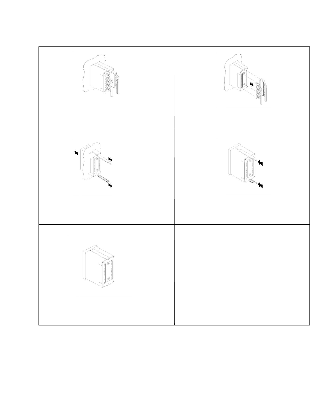
16. HOW TO RETURN CONTROLLERS FOR REPAIR
1
Installed in panel. Turn “Off” all power sources to
controller before going to step 2.
3
2
Remove terminal blocks and leave wires attached.
4
Remove Rails and Rail Mounting Screws.
Slide controller forwards.
5
Controller is ready to return.
Slide Rails back on and install the Rail Mounting
Screws.
6
Call 1-574-256-5001 ask for a Returns Goods
(RG) Number (#)
Ship controller with RG # to:
Electronics Incorporated
56790 Magnetic Drive
Mishawaka, IN 46545
16
 Loading...