

Page 1

FEATURES
EA uniTFTs series
·
2.0" 320x240 / 2.8" 320x240 / 3.5" 480x320 / 4.3" 480x272
·
AACS-Display (all angle color stability, optimized backlight and TFT-Panel over widest viewing angle)
·
Superbright LED backlight over 800 cd/m²
·
Object-oriented screen layout
·
Change object during run-time: size, shape, color, content
·
Animate and move objects, alpha-blending
·
Fonts: ASCII and Unicode
·
Single supply 3.3 V or directly through USB
·
Serial Interfaces: USB, RS232, SPI, I²C
·
8 digital, freely definable I/Os built in, expandable up to 136, 4 analog inputs
·
Time (RTC), battery-buffered
·
Flash-memory as storage for pictures, fonts, menus and log-files
·
Internal functions for calculation as well as programmability
·
Tone feedback build-in
ORDERING CODES
2.0" TFT 320x240 dots, PCAP, white LED backlight (external dimensions: 65 x 43 mm) EA uniTFTs020-ATC
2.8" TFT 320x240 dots, PCAP, white LED backlight (external dimensions: 84 x 58 mm) EA uniTFTs028-ATC
3.5" TFT 480x320 dots, PCAP, white LED backlight (external dimensions: 100 x 65 mm) EA uniTFTs035-ATC
4.3" TFT 480x272 dots, PCAP, white LED backlight (external dimensions: 114 x 84 mm) EA uniTFTs043-ATC
ACCESSORIES
Quick-Start Set incl. 2.8" Display
ZIF-connector 40 positions 0.5 mm pitch connector for FPC-cable EA WF050-40S
FPC-cable 40 postitions, 0.5 mm pitch, 102 mm long EA KF050-40
USB-Kabel Type A -> Mini USB around 1 m EA KUSB-MINI
Printing and typographical errors reserved.
ELECTRONIC ASSEMBLY reserves the right to change specification without prior note.
Page 2

EA uniTFTs series
Content
General .......................................................................................................................................................... 4
Software ......................................................................................................................................................... 5
Objects ..................................................................................................................................................... 6
Styles / StyleSheets ................................................................................................................................... 8
Coordinate system and angle ...................................................................................................................... 9
Multi language - String files ........................................................................................................................ 10
Boot-menu ............................................................................................................................................... 11
Firmware-update ....................................................................................................................................... 12
Hardware ...................................................................................................................................................... 14
Pin assignment ........................................................................................................................................ 16
Power supply ........................................................................................................................................... 19
Serial interfaces ........................................................................................................................................ 20
RS232 ................................................................................................................................................ 20
SPI ..................................................................................................................................................... 21
I²C ...................................................................................................................................................... 23
USB ................................................................................................................................................... 23
Touch-panel .............................................................................................................................................. 25
I/O ........................................................................................................................................................... 26
Analogue input ......................................................................................................................................... 27
PWM output ............................................................................................................................................. 28
Time ........................................................................................................................................................ 29
Memory ................................................................................................................................................... 30
Electrical characteristics ........................................................................................................................... 31
Dimension EA uniTFTs020-ATC .................................................................................................................. 33
Dimension EA uniTFTs028-ATC .................................................................................................................. 37
Dimension EA uniTFTs035-ATC .................................................................................................................. 41
Dimension EA uniTFTs043-ATC .................................................................................................................. 45
Protocol / Data transfer.................................................................................................................................. 49
Short protocol ........................................................................................................................................... 51
Small protocol .......................................................................................................................................... 55
Commands ................................................................................................................................................... 59
Command syntax ..................................................................................................................................... 61
Terminal window ....................................................................................................................................... 63
Text output / strings .................................................................................................................................. 69
Pictures ................................................................................................................................................... 83
Touch functions ........................................................................................................................................ 85
Draw / graphic primitives ............................................................................................................................ 93
Bargraph / instruments .............................................................................................................................. 99
Keyboard .............................................................................................................................................. 105
Input elements ........................................................................................................................................ 108
Action / Animation ................................................................................................................................... 118
Object management ................................................................................................................................ 130
Styles .................................................................................................................................................... 136
Macros .................................................................................................................................................. 144
Variables/ Registers ................................................................................................................................ 160
I/O Port .................................................................................................................................................. 174
Analogue Input ........................................................................................................................................ 178
PWM output ........................................................................................................................................... 179
Serial master interfaces ........................................................................................................................... 181
Sound .................................................................................................................................................... 191
Time ...................................................................................................................................................... 192
Files / Memory ....................................................................................................................................... 196
System commands ................................................................................................................................. 206
Answer / Feedback ................................................................................................................................. 215
Functions and Calculations ........................................................................................................................... 224
Printing and typographical errors reserved.
ELECTRONIC ASSEMBLY reserves the right to change specification without prior note.
2 / 252
Page 3

EA uniTFTs series
uniTFTDesigner ............................................................................................................................................ 234
Short cuts .............................................................................................................................................. 236
Language Editor ...................................................................................................................................... 238
Register Editor........................................................................................................................................ 239
Macro Editor ........................................................................................................................................... 240
Tools ........................................................................................................................................................... 241
Revision...................................................................................................................................................... 252
Printing and typographical errors reserved.
ELECTRONIC ASSEMBLY reserves the right to change specification without prior note.
3 / 252
Page 4

EA uniTFTs series
GENERAL
The EA uniTFTs series provides sophisticated graphical functions and intuitive menu control with its built-in instruction
set. Thanks to the integrated instruction set and the Windows design software uniTFTDesigner, not only electronics
specialists, but also experts in the field of design and user guidance are able to create the entire HMI.
The display modules are immediately ready for operation with 3.3 V, controlled via the built-in serial interfaces RS232,
SPI, I²C or USB. The modules can be operated directly through the USB, too.
Object-oriented "programming", the wide set of commands, and the integrated but extensible Unicode fonts make
"time-to-market" a breeze.
The EA uniTFT series, which forms the high-end market with larger modules, comes up with a very similar command
set:
Currently are 3 different sizes available: 5" with 800x480 dots, 7" IPS with 1024x600 dots and 1000cd/m² and 10.1"
IPS with 1280x800 dots and 1000cd/m².
Printing and typographical errors reserved.
ELECTRONIC ASSEMBLY reserves the right to change specification without prior note.
4 / 252
Page 5

EA uniTFTs series
SOFTWARE - OPERATION OF EA UNITFTS-SERIES
The presentation on the display is based on the given commands. The commands can either be transmitted at runtime
via one of the serial interfaces or combined on the internal memory in so-called macros and stored permanently. With
the help of the commands, graphic objects are created. These objects have different properties, like color, position and
built-in actions. These properties can be changed at any time, for example a string or the position of a touch-sensitive
button can be changed.
All conceivable objects can be arbitrarily placed, moved and deleted. Windows font sets are stored directly in the
display's memory. Thanks to automatic ASCII and Unicode switching, a wide variety of systems are supported flexibly,
Chinese characters included. Elegant effects like fading in or out are already integrated. Style sheets can be used to
create consistent designs. Images JPEG, PNG and many more (also transparent) can be integrated. Together with the
integrated (EA uniTFTs035-ATC and EA uniTFTs043-ATC), battery-buffered time base, events can be documented
together with a time stamp or processes can be controlled completely autonomously without an external computer.
Printing and typographical errors reserved.
ELECTRONIC ASSEMBLY reserves the right to change specification without prior note.
5 / 252
Page 6

EA uniTFTs series
Objects
Every picture, text element and button is a so-called object. Each object got its own, individual object ID, which makes
it uniquely identifiable. The object ID can be used to change the properties of an object at any time (size, position...).
You can use 0 as ID for creating simple graphical objects. These objects are rendered directly to the background and
aren't editable and manipulable any more. If you assign an already existing object ID to a new object, the previous
object will be overwritten.
Commands for object management can be found here.
Object position / Anchor
General anchors
The position of an object is based on the coordinates (origin: bottom left edge) related to the object anchor. Each
object has 9 fixed anchors. Transformation on the object (e.g. rotation or shear) will be applied to the active anchor.
Strings and anchors
Strings have additional 9 anchors used to align objects (e.g. an underscore line) to the text base line.
Special case: Anchor 0
Each object has additionally a freely definable anchor. For circles, ellipses, and stars, the object anchor 0 is the
Printing and typographical errors reserved.
ELECTRONIC ASSEMBLY reserves the right to change specification without prior note.
6 / 252
Page 7

construction point.
EA uniTFTs series
Example: The pointer should rotate around the centre of
the circle. The pointers 9 standard anchors (shown in
dark grey) are not useful in this case because none of the
defaults are located in the right position. The anchor 0
can be placed pixel-precise (#OAS) as shown, and this
custom location marks the correct rotation point for the
pointer object.
Printing and typographical errors reserved.
ELECTRONIC ASSEMBLY reserves the right to change specification without prior note.
7 / 252
Page 8

EA uniTFTs series
Styles / StyleSheets
Styles can be used to create consistent design. There are
- DrawStyles
- TextStyles
- ButtonStyles
Before placing any graphic object or text object, a DrawStyle or a TextStyle need to be defined. A DrawStyle defines
the pen type and a fill color and the TextStyle the font and it's size.
DrawStyle:
Color, gradients, pattern and pen for (out)lines are defined in a DrawStyle.
TextStyle:
The appearance of a string is defined in a TextStyle. A TextStyle is based on a DrawStyle for color and some font
specification for size, alignment and spacing.
ButtonStyle:
Touch buttons and switches are defined by a ButtonStyle, which consists of a TextStyle for labeling and DrawStyles
for background painting.
ColorRamp:
Filling an object can be done with solid color or with some gradient. Those gradient and its colors are defined in
ColorRamps and can be used linear or radial.
The Windows tools uniTFTDesigner supports StyleSheets that contain a collection of several Draw, Text, and
ButtonStyles ans also ColorRamps.
The commands related to styles and colorramps can be found here.
Printing and typographical errors reserved.
ELECTRONIC ASSEMBLY reserves the right to change specification without prior note.
8 / 252
Page 9

EA uniTFTs series
Coordinate system and angle
The coordinate system refers directly to the display resolution of the module with the origin 0|0 placed in the lower left
corner of the display. For example the EA uniTFTs028-A has a drawing field of 320 x 240 dots. Valid coordinates for
this display are 0..319 and 0..239 hence.
Angles are given in the mathematical sense of rotation (counter-clockwise). 0° is horizontally right. Besides
instruments rotation is available in 90° steps:
Printing and typographical errors reserved.
ELECTRONIC ASSEMBLY reserves the right to change specification without prior note.
9 / 252
Page 10

EA uniTFTs series
Multi language - String files
In an increasingly interdependent world of international assignments, supporting multiple languages is a must. The EA
uniTFTs-Series with its unicode support is part of the solution. Without unicode it's basically impossible to work with
Chinese characters e.g..
The second part of supporting internationalization are string files: these text files provide a database of strings to be
displayed. In macro files, strings are referenced by an index, then at runtime this index is replaced with the
corresponding text taken from the string file.
Further details can be found by looking at the command description under #VFL or the examples.
Printing and typographical errors reserved.
ELECTRONIC ASSEMBLY reserves the right to change specification without prior note.
10 / 252
Page 11

EA uniTFTs series
Boot menu
Multiple projects can be stored on the integrated memory. The project which is started automatically is defined using
the "start.emc" file. To load a different project, the start file need to be updated, or on touch enabled panels, a project
can be selected via the boot menu:
When switching on the device (or after hardware reset), wipe over the touch panel several times in short interval.
To avoid mis-use by the operator, the boot menu can be deactivated. For this purpose, an empty file named
"bootmenu.off" must be placed in the root directory of the memory. This can be done using mass storage mode and
Windows Explorer to transfer the file, or directly via uniTFTs commands:
#FWO</bootmenu.off>
#FWC
In addition to project selection, the boot menu offers the option to start test mode, or to display information about the
module. It provides the version, protocol status, baudrate, SPI mode, I²C bus address etc
Printing and typographical errors reserved.
ELECTRONIC ASSEMBLY reserves the right to change specification without prior note.
11 / 252
Page 12

EA uniTFTs series
Firmware-update
To use the latest features of the EA uniTFTs-Series, it might be necessary to update the internal firmware of the
module. There are two ways of updating, through the serial interface or with the help of the SD-Card.
Firmware-update via serial interface and Windows PC:
·
Save the firmware file (e.g. EA_uniTFTs_V1_1.fw) to your local drive
·
Connect the EA uniTFT with your PC
·
Start uniTRANSFER.exe (found in the Simulator_and_Tools folder of the uniTFTDesigner installation) and select
the correct serial interface to the EA uniTFTs.
·
Drag'n'Drop the firmware file to the EA uniTRANSFER window.
·
After transferring the data, a manually reset needs to be performed, then the firmware will be loaded automatically
after restart. Attention: Please do not switch of the module while updating.
·
The firmware file is deleted from the SD Card as long as the file is not marked as "read only".
Firmware update via serial interface
The firmware file also can be transferred to EA uniTFT with any system. To do this, transfer the contents of the * .fw file
1:1 (with protocol in packets) to the EA uniTFT. The transfer progress will become visible on the display module. After
successful transfer, a data check will be done automatically. If the data is correct, the update starts automatically.
Printing and typographical errors reserved.
ELECTRONIC ASSEMBLY reserves the right to change specification without prior note.
12 / 252
Page 13

EA uniTFTs series
Attention: Please do not switch of the module while updating.
Printing and typographical errors reserved.
ELECTRONIC ASSEMBLY reserves the right to change specification without prior note.
13 / 252
Page 14

EA uniTFTs series
HARDWARE
The EA uniTFTs-Series consists of a TFT-Display with LED backlight, driven by an integrated driving circuit, which is
dimmable using software commands. In 24/7 operation the backlight can be dimmed automatically to increase the
LED life-time and save energy.
The module is designed to work with 3.3 VDC. Serial data transfer is possible through RS232, SPI, I²C or direct via
USB protocol.
For simple control tasks, the module has 8 freely usable I/Os (expandable up to 136), 4 analogue inputs, one PWM
output and 3 serial interfaces (RS232, SPI and I²C).
The moudles do have an integrated capacitive touch panel. By touching the display you can enter data and make
adjustments via menu or bar graph. The labelling, size and shape of the "keys" is flexible and can also be changed
during runtime (different languages, icons). The drawing of the individual "keys", as well as the labelling is completely
taken over by the built-in software. The capacitive touchpanel has an robust glass surface that can also be operated
with thin gloves.
Front view (example EA uniTFTs043-ATC)
Printing and typographical errors reserved.
ELECTRONIC ASSEMBLY reserves the right to change specification without prior note.
14 / 252
Page 15

EA uniTFTs series
Rear view (example EA uniTFTs043-ATC)
Printing and typographical errors reserved.
ELECTRONIC ASSEMBLY reserves the right to change specification without prior note.
15 / 252
Page 16

EA uniTFTs series
Pin assignment
Pin assignment for ZIF connector. It's an FPC connector with 40 positions and 0.5 mm pitch. Bottom contact.
Printing and typographical errors reserved.
ELECTRONIC ASSEMBLY reserves the right to change specification without prior note.
16 / 252
Page 17

EA uniTFTs series
Pin Symbol I/O Description
1 GND Ground 0 V
2 VDD Power Supply 3.3 V
3 RES I Reset internal Pull-Up: (10..75 kW)
4 CS I SPI: Chip Select internal Pull-Up: (1 MW)
5 MOSI I SPI: MOSI
6 MISO O SPI: MISO
7 CLK I SPI: CLK internal Pull-Up: (1 MW)
8 RxD I RS232: Receive Data internal Pull-Up: (1 MW)
9 TxD O RS232: Transmit Data
10 DE O RS485: Transmit Enable
11 SDA I/O I²C: Serial Data internal Pull-Up: (10 kW); Pull-Up resistors can be changed for proper I²C connection
12 SCL I I²C: Serial Clock internal Pull-Up: (10 kW´
13 SBUF
TESTMODE
I Low: Data available in send buffer
PowerOn Low: Test mode
14 DPROT I High: Small-/Shortprotokoll active
Low: deactivated
15 A/D 0 I Analog Input 0
16 A/D 1 I Analog Input 1
17 A/D 2 I Analog Input 2
18 A/D 3 I Analog Input 3
19 I/O 0.0 I/O I/O 0.0 (Bit 0)
20 I/O 0.1 I/O I/O 0.1 (Bit 1)
21 I/O 0.2 I/O I/O 0.2 (Bit 2)
22 I/O 0.3 I/O I/O 0.3 (Bit 3)
23 I/O 0.4 I/O I/O 0.4 (Bit 4)
24 I/O 0.5 I/O I/O 0.5 (Bit 5)
25 I/O 0.6 I/O I/O 0.6 (Bit 6)
internal Pull-Up: (10 kW)
internal Pull-Up: (10 kW)
internal Pull-Down: (1 MW)
internal Pull-Up: (1 MW), Reset-state: Tri-State, default: input
26 I/O 0.7 I/O I/O 0.7 (Bit 7)
27 PWM O PWM-Output
28 DNC --- Do not connect
29 DNC --- Do not connect
30 DNC --- Do not connect
Reserved for future use
31 DNC --- Do not connect
32 DNC --- Do not connect
33 DNC --- Do not connect
Printing and typographical errors reserved.
ELECTRONIC ASSEMBLY reserves the right to change specification without prior note.
34 BUZZER O Sound PWM output for external speaker
17 / 252
Page 18

EA uniTFTs series
Printing and typographical errors reserved.
ELECTRONIC ASSEMBLY reserves the right to change specification without prior note.
18 / 252
Page 19
EA uniTFTs series
Power supply
The modules can be powered in three different ways:
Ziff-Connector Solderpadas USB
Spannung 3.3 V 3.3 V 5 V (Power over USB)
USB Lötrbücke open open closed
Attention:
In order to avoid fault currents, the "USB Power Enable" solder bridge must be set correctly. The solder bridge is
closed by default. The internal voltage regulator is now active and generates 3.3 V from the connected USB supply. If
an additional 3.3 V is now supplied externally, fault currents occur.
Printing and typographical errors reserved.
ELECTRONIC ASSEMBLY reserves the right to change specification without prior note.
19 / 252
Page 20

EA uniTFTs series
Serial interfaces
The module provides 4 serial interfaces, including RS232, SPI, I²C and USB. In addition to the USB interface, the other
interfaces can change your behaviour:
They can either be used to connect to an external host, i.e. to a higher-level controller, or used as a master interface.
By default, all interfaces are parameterized as slaves and accept the commands.
Parameterized as a master interface, it enables the control of external sensors and actuators. The display module
behaves here as a master.
As already described, the interfaces behave as slave interfaces by default and accept commands. However, as soon
as a master interface command (#H ...)is executed, the interface gets master functions.
RS232
RS232 is a standard for a serial interface.
The EA uniTFT provides one RS232 interface, that can be operated as slave (default) or as master: As slave interface
it is used to communicate with the display. All data sent to the display are interpreted as a command (with and w./o.
Small-/Short-Protocol). If you would like to send and receive any data via RS232 to other devices then you have to use
it as master. Those are handled via #H commands.
The transmission is serially asynchronous. Thus the data is converted into a bit stream and transmitted. There is no
clock signal, so transmitter and receiver need to work with the same data rate (so-called baud rate). RS232 is a
voltage interface, such that data is transmitted using changing voltage levels. In the PC world and industrial controls,
levels of + 12V and - 12V are defined as standard. With boards or micro-controllers levels of 0V and VDD (in the case
of EA uniTFTs-Series 3.3 V) are common. To adjust the signal levels, there are some possibilities in the form of level
shifters (e.g., ICL232, MAX202). RS232 consists of "listening" and "talking" lines that are crossed between the two
parties.
In the EA uniTFTs-Series, the data format is fixed to 8-N-1:
The EA uniTFTs-Series works with the following baud rates:
Baud Error Baud Error
9600 +0.04 115200 +0.64
19200 -0.08 230400 -0-80
38400 +0.16 460800 +2.08
57600 -0.08 921600 -3.68
Printing and typographical errors reserved.
ELECTRONIC ASSEMBLY reserves the right to change specification without prior note.
20 / 252
Page 21

EA uniTFTs series
The parameters (baud rate) are set using command #XCR (higher-level control unit), and the master interface is set
with the command #HRP. Those definition can be done in start.emc e.g.
Application notes
RS232 V24 - Interface to a PC (EA uniTFTs)
RS485 / RS422 interface
With this simple external IC a communicaion to any RS-485 and RS-422 can be done.
RS485 - Interface to a PLC (EA uniTFT )
SPI
The Serial Peripheral Interface is a bus system for serial synchronous data transfer.
The EA uniTFT provides a SPI interface: AS default the interface has Slave functionality and is used to communicate
with the display. All data sent to the display are interpreted as a command (with and w./o. Small-/Short-Protocol).
Would you like to send and receive any data via SPI to other devices like temperature sensor, then you have to use
the Master interface. Those are handled via #H commands.
Printing and typographical errors reserved.
ELECTRONIC ASSEMBLY reserves the right to change specification without prior note.
21 / 252
Page 22
EA uniTFTs series
The SPI is working with 4 lines:
·
MOSI (Master Out ® Slave In) or SDO (Serial Data Out) or DO
·
MISO (Master In ¬ Slave Out) or SDI (Serial Data In) or DI
·
SCK (Serial Clock) - Shift clock
·
SS (Slave Select ® Addressing) or CS (Chip Select)
SPI works with a bidirectional transmission principle, meaning that data is exchanged between the connected devices
at the same time. The communication is controlled by the master using the SCK line.
The protocol for data transfer is not defined in SPI, therefore there are different configuration possibilities, which are
defined by the parameters Clock Polarity, Clock Phase and Data Order. The default setting is SPI mode 3 with DORD
= 0. The commands #XCS and #HSP (master interface) ) set the mode 0..3. Alternatively the command can be stored
directly into the boot file <start.emc>.
Mode CPOL CPHA DORD (0) - MSB First DORD (1) - LSB First
0 0 0
1 0 1
2 1 0
Printing and typographical errors reserved.
ELECTRONIC ASSEMBLY reserves the right to change specification without prior note.
22 / 252
Page 23

EA uniTFTs series
3 1 1
The maximum clock frequency is 1 MHz. The module needs some time to prepare data for transfer. That means a wait
cycle (no activity on the SCK-line) of at least 50 ms is required before reading data.
I²C
I²C stands for Inter-Integrated Circuit and is a serial data-bus developed by Phillips.
The EA uniTFT provides one I²C interface: As default the interface is parametrized as Slave and used to communicate
with the display. All data sent to the display are interpreted as a command (with and w./o. Small-/Short-Protocol).
Would you like to send and receive any data via I²C to any other device like temperature sensor, then you have to use
the Master functionality (pins 43 and 44). Those are handled via #H commands.
The bus is a Master-Slave implementation and needs 2 signal lines:
·
SCL (Serial Clock Line)
·
SDA (Serial Data Line)
The electrical specification defines that both lines are terminated with a pull-up resistor at VDD, because all devices
connected to the bus have open collector outputs. The bus clock is always given by the master, which controls the
entire communication:
After the start condition, the slave address follows. In this case, bit 0 is the so-called R/W bit and determines whether
the slave should be read (1) or data is transmitted (0). The data exchange takes place until the master executes the
stop condition. More detailed information can be found in the I²C specification. The default I²C bus address is 0xDE (as
8-Bit address, including R/W bit, as 7-Bit address without R/W bit it's 0x6F) when writing to the slave unit.
The command #XCI and #HIP (master interface) can change the I²C write address to any other address. Alternatively
the command can be written directly into the boot file <start.emc>.
The maximum frequency in slave mode is 400 kHz, the master interface is capable up to 1 MHz.The module needs
some time to prepare data for transfer. That means a wait cycle (no activity on the SCL-line) of at least 50 ms is
required before reading data.
Printing and typographical errors reserved.
ELECTRONIC ASSEMBLY reserves the right to change specification without prior note.
23 / 252
Page 24
EA uniTFTs series
USB
The Universal Serial Bus is a serial bus system for interfacing a PC with other peripherals. It's based on differential
data transfer. The bus topology is a strict master-slave communication (Exception: On the Go devices). In the case of
EA uniTFTs-Series the PC/Master needs to coordinate the communication. The module has a CDC (Communications
Device Class) and is found by Windows PC's as a virtual COM-Port:
Description Value
Device Class 2
USB Vendor ID 0x2DA9
USB Product ID 0x2454
Device description EA uniTFT
To program the module, adjust settings or to perform initial tests, we recommend using the USB interface. It's easy to
connect, the transfer rate is fast and no interface parameters need to be specified. The driver for Windows can be
downloaded on our web-page: http://www.lcd-module.de/fileadmin/downloads/EA_CDCdriver_V5_2.zip
Attention:
A protocol has to be used in USB CDC mode. It's impossible to use the USB interface without a protocol, which
means pin 22 (primary connector) must not be set to GND. The high-speed connection of USB leads to buffer
overflow, which are prevented by the protocol.
Printing and typographical errors reserved.
ELECTRONIC ASSEMBLY reserves the right to change specification without prior note.
24 / 252
Page 25

EA uniTFTs series
Touch-panel
The modules all do have a optically bonded capcitive touchpanels, which is used for mounting, too. By touching the
display you can enter data and adjust settings via menus or bar graphs. The labelling of the "keys" is flexible and can
also be changed during runtime (different languages, icons). The drawing of the individual "keys" as well as the
labelling is completely handled by the built-in software.
Printing and typographical errors reserved.
ELECTRONIC ASSEMBLY reserves the right to change specification without prior note.
25 / 252
Page 26

EA uniTFTs series
I/O - digital in- and outputs
The module has 8 digital I/Os (CMOS level, nonfloating). The input range is 0... 3.3 V. All 8 I/Os have a
weak pull-up at 1 MW and are set as inputs after reset.
Remark: The logic is not designed for time-critical
operations; i.e. it is not a real-time operating system
By using one or more external (max. 8) MCP23017-E
(16 I/Os per IC), the total number of I/Os can be
expanded up to 136. Therefore the port-expanders are
connected to pins 35-37 (see application example).
The maximum power of the MCP23017-E is 700 mW in total. The maximum current load for a single pin is 25 mA,
which makes it possible to directly operate a low current LED. If a higher load is required, the I/O current must be
amplified with suitable circuitry, e.g. through an external transistor. For more details see Electrical characteristics
The overview of the software commands for the I/Os can be found under the chapter 'I/O Port'.
Printing and typographical errors reserved.
ELECTRONIC ASSEMBLY reserves the right to change specification without prior note.
26 / 252
Page 27

EA uniTFTs series
Analogue input
The module uses 4 analogue inputs with a resolution of
12 bit and an input range of 0 V...VDD. The input range
can be arbitrarily expanded with the help of external
voltage dividers or amplifiers. Every single input is
referenced to GND and has an input resistance of about
1 MW. The absolute accuracy is 11 bits, as reference
VDD/2 is used.
This enables the display to measure analogue voltages,
e.g. to display or save the values for further processing.
The exceeding or undershooting of a threshold can also
be used to trigger an alarm.
The overview of the software commands for the analogue
inputs can be found under the chapter 'Analogue Input'
Printing and typographical errors reserved.
ELECTRONIC ASSEMBLY reserves the right to change specification without prior note.
27 / 252
Page 28

EA uniTFTs series
PWM output
The module has the option of controlling external
components via a PWM signal (pulse width modulation).
At constant frequency (adjustable from 2 Hz to 1 MHz
#HFO), the duty cycle of a rectangular pulse is
changed. Modulation changes the ratio between the onand off-time and thus the characteristics of the output
signal. In this way, electromechanical components such
as motors can be driven or even a quasi-analogue
voltage can be generated. The variation of the duty
cycles supports a low engine speed/voltage with a short
start-up time or a high motor speed/voltage with a long
start-up time. The output levels are at 0V and VDD.
Printing and typographical errors reserved.
ELECTRONIC ASSEMBLY reserves the right to change specification without prior note.
28 / 252
Page 29
EA uniTFTs series
Time / RTC
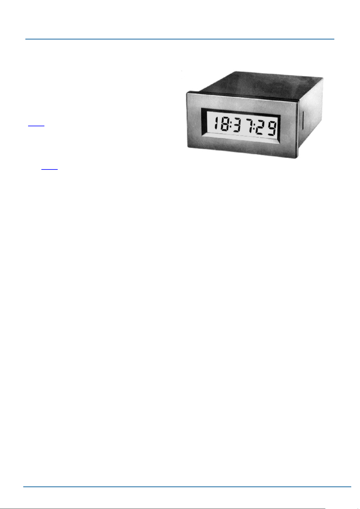
An RTC can be connected to the EA uniTFTs-Series,
the EA uniTFTs035-ATC and EA uniTFTs043-ATC has
the RTC already build in. In addition to providing timestamps for log files, the time and date can be displayed
on the screen. On delivery, the time is set to Central
European Time (CET / MEZ). Depending on the location
it may be necessary to set the device to local time
(#WTD). In the event of a voltage drop, or when the
module is switched off, the clock is powered by a button
cell (D377), so that the correct time is retained.
Due to component tolerances and temperature
fluctuations, deviations of up to 0.02% are possible. The
deviation can be reduced by repeatedly adjusting the
time (#WTD).
If your module has no built-in RTC, but you need the
time and RTC functions an external RTC has to be
connected. The part MCP7940N - SN is supported:
Printing and typographical errors reserved.
ELECTRONIC ASSEMBLY reserves the right to change specification without prior note.
29 / 252
Page 30

EA uniTFTs series
Memory
The module has a built-in flash memory. The size is 31
MByte.
This memory is used to store all data, whether
generated at runtime, e.g. log files, or pre-loaded as
project data, such as macro files, pictures, animations
and icons.
Printing and typographical errors reserved.
ELECTRONIC ASSEMBLY reserves the right to change specification without prior note.
30 / 252
Page 31
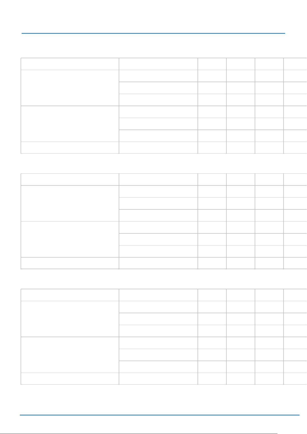
EA uniTFTs series
Elektrische Spezifikation EA uniTFT020-ATC
Value Condition min. typ. max. Unit
Backlight 0% 113 mA
Supply current 3.3 V
Supply current USB (5 V)
Brightness (100%) with PCAP
Backlight 100% 222 mA
Backlight 150% 284 mA
Backlight 0% 82 mA
Backlight 100% 158 mA
Backlight 150% 201 mA
700
850 cd/m²
Elektrische Spezifikation EA uniTFT028-ATC
Value Condition min. typ. max. Unit
Backlight 0% 113 mA
Supply current 3.3 V
Backlight 100% 236 mA
Backlight 150% 309 mA
Backlight 0% 84 mA
Supply current USB (5 V)
Brightness (100%) with PCAP
Backlight 100% 169 mA
Backlight 150% 219 mA
700
780 cd/m²
Elektrische Spezifikation EA uniTFT035-ATC
Value Condition min. typ. max. Unit
Backlight 0% 115 mA
Supply current 3.3 V
Supply current USB (5 V)
Brightness (100%) with PCAP
Backlight 100% 269 mA
Backlight 150% 368 mA
Backlight 0% 84 mA
Backlight 100% 192 mA
Backlight 150% 260 mA
480
600 cd/m²
Printing and typographical errors reserved.
ELECTRONIC ASSEMBLY reserves the right to change specification without prior note.
31 / 252
Page 32

EA uniTFTs series
Elektrische Spezifikation EA uniTFT043-ATC
Value Condition min. typ. max. Unit
Backlight 0% 131 mA
Supply current 3.3 V
Supply current USB (5 V)
Brightness (100%) with PCAP
Backlight 100% 362 mA
Backlight 150% 562 mA
Backlight 0% 89 mA
Backlight 100% 252 mA
Backlight 150% 382 mA
750
820 cd/m²
Elektrische Spezifikation Allgemein
Value Condition min. typ. max. Unit
Operating temperature -20 70 °C
Storage temperature -30 80 °C
Storage humidity @ 60°C 90 % RH
Operating voltage 3.1 3.3 3.5 V
Input low voltage (except USB,I/O) -0,3 0 0.3*VDD V
Input high voltage (except USB,I/O) VDD*0.7 VDD+0.3 V
Output low voltage (except USB,I/O) - - 0,4 V
Output high voltage (except USB, I/O) VDD-0.5 - - V
single
Output current I/O
all
I²C-bus pull-up 10 kΩ
- - 2 mA
- - 16
mA
(total)
Printing and typographical errors reserved.
ELECTRONIC ASSEMBLY reserves the right to change specification without prior note.
32 / 252
Page 33

EA uniTFTs series
Printing and typographical errors reserved.
ELECTRONIC ASSEMBLY reserves the right to change specification without prior note.
33 / 252
Page 34

EA uniTFTs series
Dimension EA uniTFTs020-ATC
Printing and typographical errors reserved.
ELECTRONIC ASSEMBLY reserves the right to change specification without prior note.
34 / 252
Page 35

EA uniTFTs series
Printing and typographical errors reserved.
ELECTRONIC ASSEMBLY reserves the right to change specification without prior note.
35 / 252
Page 36

EA uniTFTs series
Printing and typographical errors reserved.
ELECTRONIC ASSEMBLY reserves the right to change specification without prior note.
36 / 252
Page 37

EA uniTFTs series
Printing and typographical errors reserved.
ELECTRONIC ASSEMBLY reserves the right to change specification without prior note.
37 / 252
Page 38

EA uniTFTs series
Dimension EA uniTFTs028-ATC
Printing and typographical errors reserved.
ELECTRONIC ASSEMBLY reserves the right to change specification without prior note.
38 / 252
Page 39

EA uniTFTs series
Printing and typographical errors reserved.
ELECTRONIC ASSEMBLY reserves the right to change specification without prior note.
39 / 252
Page 40

EA uniTFTs series
Printing and typographical errors reserved.
ELECTRONIC ASSEMBLY reserves the right to change specification without prior note.
40 / 252
Page 41

EA uniTFTs series
Printing and typographical errors reserved.
ELECTRONIC ASSEMBLY reserves the right to change specification without prior note.
41 / 252
Page 42

EA uniTFTs series
Dimension EA uniTFTs035-ATC
Printing and typographical errors reserved.
ELECTRONIC ASSEMBLY reserves the right to change specification without prior note.
42 / 252
Page 43

EA uniTFTs series
Printing and typographical errors reserved.
ELECTRONIC ASSEMBLY reserves the right to change specification without prior note.
43 / 252
Page 44

EA uniTFTs series
Printing and typographical errors reserved.
ELECTRONIC ASSEMBLY reserves the right to change specification without prior note.
44 / 252
Page 45

EA uniTFTs series
Printing and typographical errors reserved.
ELECTRONIC ASSEMBLY reserves the right to change specification without prior note.
45 / 252
Page 46

EA uniTFTs series
Dimension EA uniTFTs043-ATC
Printing and typographical errors reserved.
ELECTRONIC ASSEMBLY reserves the right to change specification without prior note.
46 / 252
Page 47

EA uniTFTs series
Printing and typographical errors reserved.
ELECTRONIC ASSEMBLY reserves the right to change specification without prior note.
47 / 252
Page 48

EA uniTFTs series
Printing and typographical errors reserved.
ELECTRONIC ASSEMBLY reserves the right to change specification without prior note.
48 / 252
Page 49

EA uniTFTs series
PROTOCOL / DATA TRANSFER
The transmission protocol is identical regardless of which of the 4 serial interfaces is used to transfer data from the
higher-level controller. The hardware circuit for each interface varies, which is described under the chapter "serial
interfaces".
The data transfer is embedded in a fixed frame with checksum. The EA uniTFTs-Series acknowledges this packet with
the character <ACK> (= 0x06) on successful reception or <NAK> (= 0x15) when it detects a faulty checksum or
encounters a buffer overflow. In case of a <NAK>, the complete packet is discarded and has to be sent again. An
<ACK> only confirms the correct transmission. A syntax check does not take place.
Two different protocols are implemented, the "Short Protocol" and the "Small Protocol". The short protocol works with
a CRC16 checksum and allows the transfer of larger data packets. The Small protocol was implemented mainly for
compatibility with the EA eDIPxxx series.
The maximum amount of user data per packet is 2042 bytes or 255 bytes, respectively. Commands that are larger (for
example, image or file transfers, #FWD ...) must be split into several packets. The data in the individual packets is
reassembled by the display module after receiving them successfully.
Remark:
The <ACK> has to be read (SPI and I²C). If the master doesn't receive the acknowledgement, at least one byte is lost.
In this case the time-out time needs to be observed before the packet is resent.
The protocol can be disabled on the serial port for testing purposes. To turn off the protocol, pin 14 has to be set low
(see pin assignment).
Printing and typographical errors reserved.
ELECTRONIC ASSEMBLY reserves the right to change specification without prior note.
49 / 252
Page 50

EA uniTFTs series
Printing and typographical errors reserved.
ELECTRONIC ASSEMBLY reserves the right to change specification without prior note.
50 / 252
Page 51
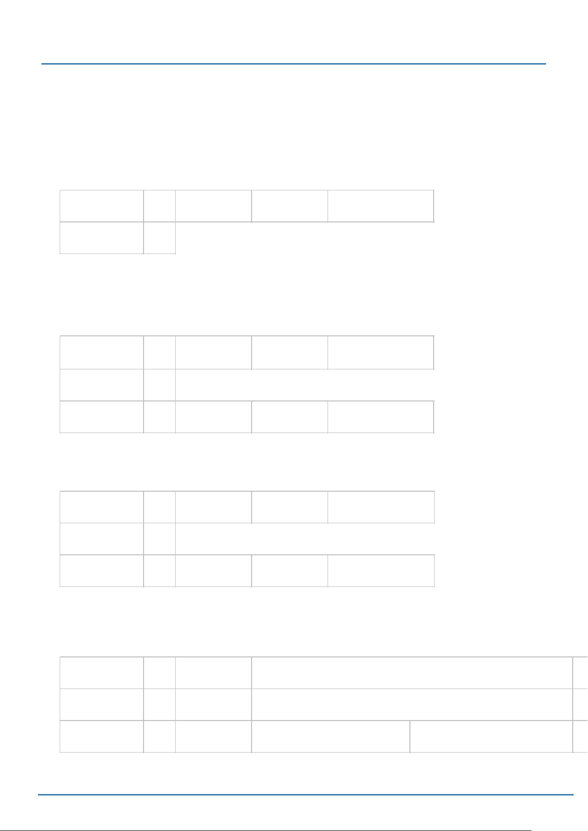
EA uniTFTs series
Short Protocol commands
1. Commands / sending data to module
This protocol command transfers data to the display. Several graphics commands can be packaged into a single
protocol packet. If the amount of data is larger than the maximum packet size, the data can be split into several
packets. The module reassembles the individual data packets.
Module receives DC3
0x13
Module sends ACK
0x06
length (16 Bit)
0xXX 0xXX
Data.......
0x....
crc (16 Bit)
0xXX 0xXX
2. Request data of send buffer
If data is generated in the module, it is stored in the module's send buffer. The data can be requested via the serial
interfaces. Whether data is available can be monitored via the pin 20 SBUF, or the higher-level controller can cyclically
poll the data.
Module receives DC4
0x14
Module sends ACK
0x06
Module sends DC3
0x13
length (16 Bit)
0x01 0x00
length (16 Bit)
0xXX 0xXX
'S'
0x53
Data.......
0x....
crc (16 Bit)
0x30 0x08
crc (16 Bit)
0xXX 0xXX
3. Repeat last data packet
If a packet received from the module is faulty (wrong length or checksum) it can be requested again:
Module receives DC4
0x14
Module sends ACK
0x06
Module sends DC3
0x13
length (16 Bit)
0x01 0x00
length (16 Bit)
0xXX 0xXX
'R'
0x52
Data.......
0x....
crc (16 Bit)
0x11 0x18
crc (16 Bit)
0xXX 0xXX
4. Request buffer information
This command queries whether user data is ready (= Pin20 SBUF) and also indicates how much free space is left in
the device's receive buffer.
Module receives DC4
0x14
Module sends ACK
0x06
Module sends DC4
0x14
length (16 Bit)
0x01 0x00
length (16 Bit)
0x04 0x00
'I'
0x49
send buffer bytes ready (16 Bit)
0xXX 0xXX
receive buffer bytes free (16 Bit)
0xXX 0xXX
crc (16 Bit)
0x4B 0xBB
crc (16 Bit)
0xXX 0xXX
Printing and typographical errors reserved.
ELECTRONIC ASSEMBLY reserves the right to change specification without prior note.
51 / 252
Page 52
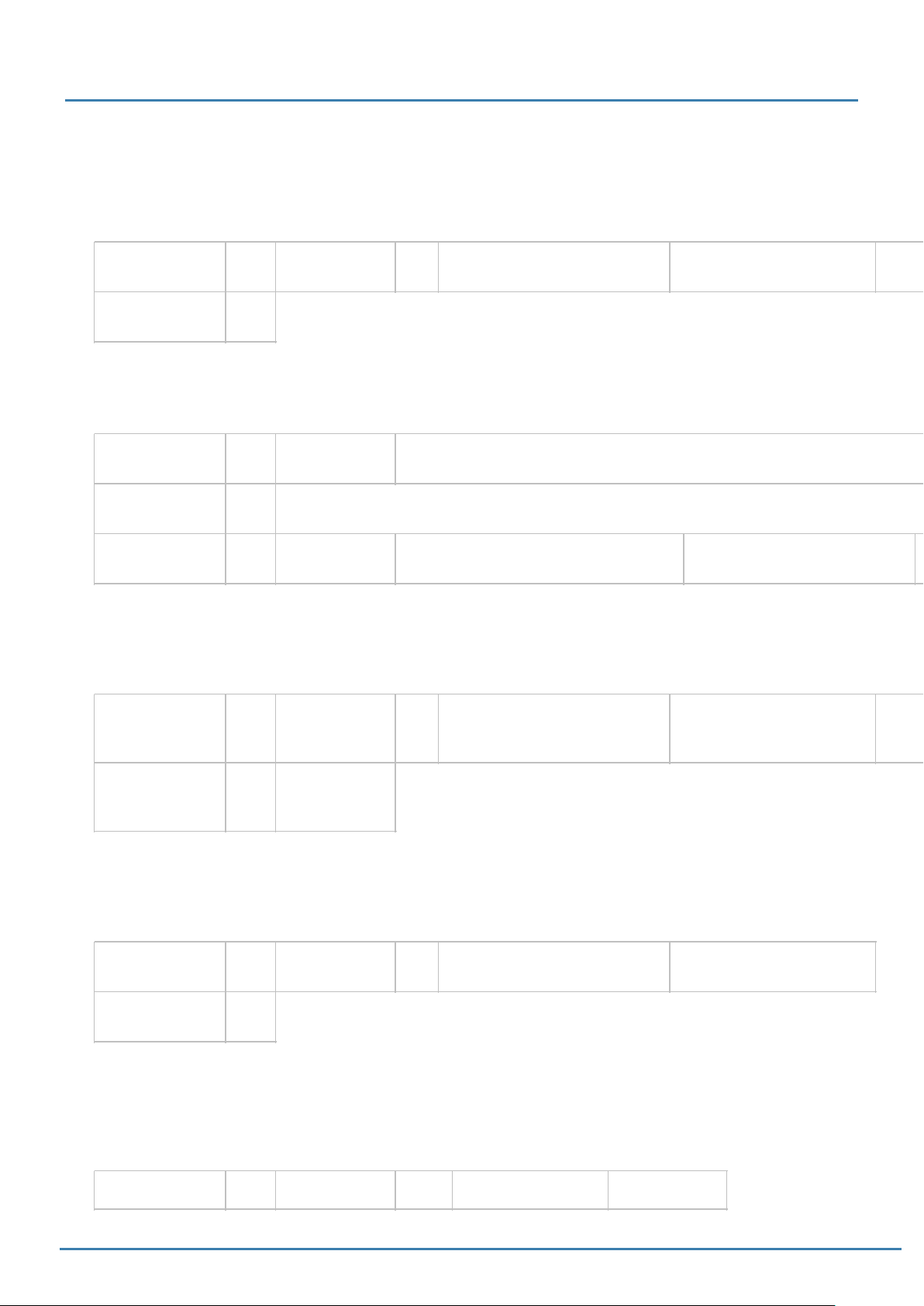
EA uniTFTs series
5. Protocol settings
This can be used to limit the maximum packet size that the display may send. The default maximum packet size is
2042 bytes. Furthermore, the time-out can be set in 1 / 1000s. The time-out is activated when individual bytes have
been lost. After the timeout, the entire packet must be retransmitted.
Module receives
Default values
Module sends ACK
DC4
0x14
0x06
length (16 Bit)
0x05 0x00
'D'
packet size send buffer (16 Bit)
0x44
0xFA 0x07 (=2042 Byte)
Time-out (16 Bit) in ms
0xD0 0x07 (=2 seconds)
6. Protocol information
Request protocol settings (see 5.).
Module receives DC4
0x14
Module sends ACK
0x06
Module sends DC4
0x14
length (16 Bit)
0x01 0x00
length (16 Bit)
0x06 0x00
'P'
0x50
maximum packet size send buffer (16 Bit)
0xFA 0x07 (=2042 Byte)
packet size Send buffer (16 Bit)
0xXX 0xXX
7. RS485 address select / deselect
With this command, a module can be selected or deselected on the RS485 bus. By default, the module with address
7 is always active.
crc (16 Bit)
0x98 0xF5
Time-out (16 Bit) in ms
0xXX 0xXX
Module receives
Default values
Module sends ACK
DC4
0x14
0x06
----
length (16 Bit)
0x03 0x00
® select
® deselect
'A'
0x41
'S' (=select)
'D' (=deselect)
0x53 or 0x44
RS485-address
0xXX
8. RS485 enable signal - delay
Some RS485 masters take some time to change the enable signal, e.g. to switch from write to read mode. In order to
enable successful communication with these devices, this command can be used to delay switching to write mode.
Module receives
Default values
Module sends ACK
DC4
0x14
0x06
length (16 Bit)
0x03 0x00
'T'
0x54
Delay in 10 us
0x00 0x00
crc (16 Bit)
0xE9 0x7E
9. Request interface exclusively
All 4 serial ports are handled in parallel and equivalently after reset. To ensure that a sequence of protocol packets is
executed without interruption, the other serial interfaces can be disabled so the active interface can communicate with
the module exclusively. This is useful, for example, for a project update via USB.
crc (16 Bit)
0xXX 0xXX
Module receives DC4 length (16 Bit) 'G' 0x00 = Release crc (16 Bit)
Printing and typographical errors reserved.
ELECTRONIC ASSEMBLY reserves the right to change specification without prior note.
52 / 252
Page 53
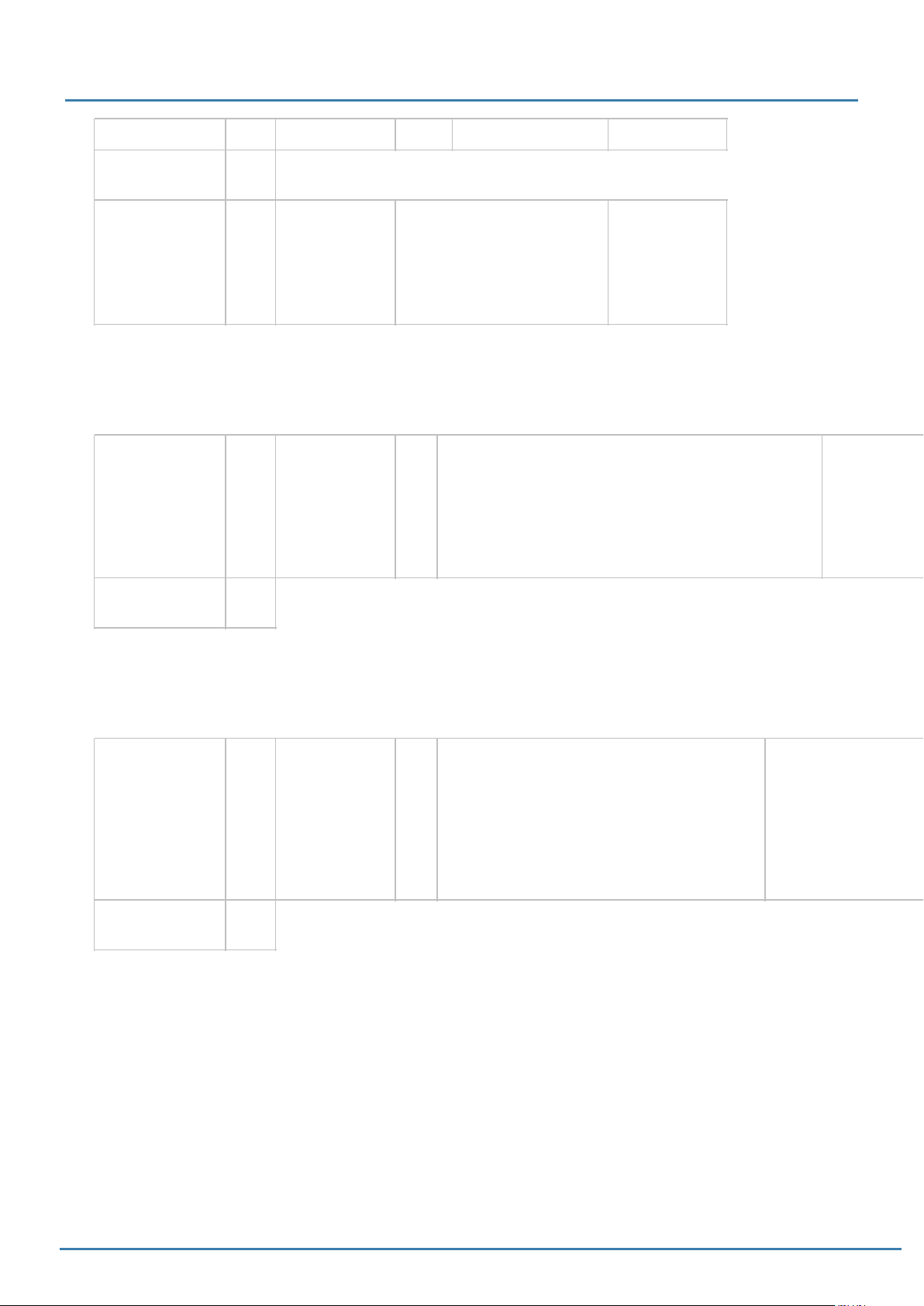
0x14 0x02 0x00 0x47 0x01 = Request 0xXX 0xXX
Module sends ACK
0x06
EA uniTFTs series
Module sends DC4
0x14
length (16 Bit)
0x01 0x00
active (16 Bit)
0x00 = all
0x01 = RS232
0x02 = SPI
0x03 = IIC
0x04 = USB
crc (16 Bit)
0xXX 0xXX
10. Break-Command, Break / Stop execution
If a continuous loop has been programmed in a macro or if a normal process flow is blocked, this command can be
used to interrupt and quit. This command is also suitable for update processes.
Module receives
Default values
Module sends ACK
DC4
0x14
0x06
length (16 Bit)
0x02 0x00
'C'
break
0x43
0x01 = Wait command
0x02 = actual macro file
0x04 = Clear send buffer
0x08 = Clear receive buffer
0x10 = Delete macro definitions (e.g. port macros)
0xFF = Stop everything
11. Hardware Reset
The module is restarted with this protocol command. Depending on the parameter, various start options can be
selected to automatically run after the reset.
crc (16 Bit)
0xXX 0xXX
Module receives
Default values
Module sends ACK
DC4
0x14
0x06
Länge (16 Bit)
0x02 0x00
'B'
Option
0x42
0x00 = normal restart
0x01 = Restart with test mode
0x02 = Restart without running 'start.emc'
0x03 = Restart without loading default styles
0x04 = Show boot-menu (project selection)
0x05 = Reserved
0x06 = Mass Storage Mode (from V1.2)
crc (16 Bit)
0xXX 0xXX
CRC-Calculation
A cyclic redundancy check (CRC) is used to calculate the checksum. A common and well known CRC exam is the
CRC-CCITT. The starting value is 0xFFFF. The following is a typical C implementation. The functions must be called
externally. The checksum must be preallocated with the starting value.
//---------------------------------------------------------------------------//function: buffer2crc16()
//input: ptr data, ptr CRC, block length
//output: --//descr: CRC-CCITT of a buffer
//----------------------------------------------------------------------------
void buffer2crc16(UBYTE *dat, UINT16 *pCRC, UINT32 len)
Printing and typographical errors reserved.
ELECTRONIC ASSEMBLY reserves the right to change specification without prior note.
53 / 252
Page 54

EA uniTFTs series
{
while(len--)
crc16(*dat++, pCRC);
}
//---------------------------------------------------------------------------//function: sp_crc16()
//input: data, ptr CRC
//output: --//descr: CRC_CCITT (x^16+x^12+x^5+1 = 1 0001 0000 0010 0001 = 0x1021
//----------------------------------------------------------------------------
void crc16 (UBYTE dat, volatile UINT16 * crc)
{
register UINT16 lcrc = *crc;
lcrc = (lcrc >> 8) | (lcrc << 8);
lcrc ^= dat;
lcrc ^= (lcrc & 0xFF) >> 4;
lcrc ^= lcrc << 12;
lcrc ^= (lcrc & 0xFF) << 5;
*crc = lcrc;
}
Printing and typographical errors reserved.
ELECTRONIC ASSEMBLY reserves the right to change specification without prior note.
54 / 252
Page 55
EA uniTFTs series
Small Protocol commands
1. Commands / data send to module
This protocol command transfers data to the display. Several graphics commands can be packaged in a protocol
package. If the data is larger than the maximum packet size, the data can be split into several packets. The module
reassembles the individual data packets.
Module receives DC1
0x11
Module sends ACK
0x06
length (8 Bit)
0xXX
Data.......
0x....
bcc (8 Bit)
0xXX
2. Request data of send buffer
If data is generated in the module, it is stored in the module's send buffer. The data can be requested via the serial
interfaces. Whether data is available can be monitored via the pin 20 SBUF, or the higher-level controller can cyclically
poll the data.
Module receives DC2
0x12
Module sends ACK
0x06
Module sends DC1
0x11
length (8 Bit)
0x01
length (8 Bit)
0xXX
'S'
0x53
Data.......
0x....
bcc (8 Bit)
0x66
bcc (8 Bit)
0xXX
3. Repeat last data packet
If a received packet of the module is faulty (wrong length or checksum) it can be requested again:
Module receives DC2
0x12
Module sends ACK
0x06
Module sends DC1
0x11
length (8 Bit)
0x01
length (8 Bit)
0xXX
'R'
0x52
Data.......
0x....
bcc (8 Bit)
0x65
bcc (8 Bit)
0xXX
4. Request buffer information
This command queries whether user data is ready (= Pin20 SBUF) and also indicates how much free space is left in
the device's receive buffer.
Module receives DC2
0x12
Module sends ACK
0x06
Module sends DC2
0x12
length (8 Bit)
0x01
length (8 Bit)
0x02
'I'
0x49
send buffer bytes ready (8 Bit)
0xXX
receive buffer bytes free (8 Bit)
0xXX
bcc (8 Bit)
0x5C
bcc (8 Bit)
0xXX
Printing and typographical errors reserved.
ELECTRONIC ASSEMBLY reserves the right to change specification without prior note.
55 / 252
Page 56
EA uniTFTs series
5. Protocol settings
This can be used to limit the maximum packet size that the display may send. As default a packet size with up to
2042 bytes of user data is set. Furthermore, the time-out can be set in 1 / 1000s. The time-out is activated when
individual bytes have been lost. After the timeout, the entire packet must be retransmitted.
Module receives
Default values
Module sends ACK
DC2
0x12
0x06
length (8 Bit)
0x03
'D'
packet size send buffer (8 Bit)
0x44
0xFF
Time-out (8 Bit) in 1/100s
0xC8 (=2 seconds)
6. Protocol information
Request protocol settings (see 5.).
Module receives DC2
0x12
Module sends ACK
0x06
Module sends DC2
0x12
length (8 Bit)
0x01
length (8 Bit)
0x03
'P'
0x50
maximum packet size send buffer (8 Bit)
0xFF
packet size send buffer (8 Bit)
0xXX
7. RS485 address select / deselect
With this command, a module can be selected or deselected on the RS485 bus. By default, the module with address
7 is always active.
bcc (8 Bit)
0x20
Time-out (8 Bit) in ms
0xXX
Module receives
Default values
Module sends ACK
DC2
0x12
0x06
----
length (8 Bit)
0x03
® select
® deselect
'A'
0x41
'S' (=select)
'D' (=deselect)
0x53 or 0x44
RS485-address
0xXX
8. RS485 enable signal - delay
Some RS485 masters take some time to change the enable signal, e.g. to switch from write to read mode. In order to
enable successful communication with these devices, this command can be used to delay switching to write mode.
Module receives
Default values
Module sends ACK
DC2
0x12
0x06
length (8 Bit)
0x03
'T'
0x54
Delay in 10 us
0x00 0x00
bcc (8 Bit)
0x69
9. Request interface exclusively
All 4 serial ports are handled in parallel and equivalently after reset. To ensure that a sequence of protocol packets is
executed without interruption, the other serial interfaces can be disabled so the active interface can communicate with
the module exclusively. This is useful, for example, for a project update via USB.
bcc (8 Bit)
0xXX
Module receives DC2 length (8 Bit) 'G' 0x00 = Release bcc (8 Bit)
Printing and typographical errors reserved.
ELECTRONIC ASSEMBLY reserves the right to change specification without prior note.
56 / 252
Page 57
0x12 0x02 0x47 0x01 = Request 0xXX
Module sends ACK
0x06
EA uniTFTs series
Module sends DC2
0x12
length (8 Bit)
0x01
active (8 Bit)
0x00 = all
0x01 = RS232
0x02 = SPI
0x03 = IIC
0x04 = USB
bcc (8 Bit)
0xXX
10. Break-Command, Break / Stop execution
If a continuous loop has been programmed in a macro or if a normal process flow is blocked, this command can be
used to interrupt and quit. This command is also suitable for update processes.
Module receives
Default values
Module sends ACK
DC2
0x12
0x06
length (8 Bit)
0x02
'C'
break
0x43
0x01 = Wait command
0x02 = actual macro file
0x04 = Clear send buffer
0x08 = Clear receive buffer
0x10 = Delete macro definitions (e.g. port macros)
0xFF = Stop everything
11. Hardware Reset
The module is restarted with this protocol command. Depending on the parameter, various start options can be
selected to automatically run after the reset.
bcc (8 Bit)
0xXX
Module receives
Default values
Module sends ACK
DC2
0x12
0x06
length (8 Bit)
0x02
'B'
Option
0x42
0x00 = normal restart
0x01 = Restart with test mode
0x02 = Restart without running 'start.emc'
0x03 = Restart without loading default styles
0x04 = Show boot-menu (project selection)
0x05 = Reserved
0x06 = Mass Storage Mode (from V1.2)
BCC-Calculation
The calculation of the checksum requires a simple 8-bit sum test (modulo 256). The following is a typical C
implementation.
//---------------------------------------------------------------------------//function: buffer2bcc()
//input: ptr data, block length
//output: Byte bcc
//descr: calculate bcc for a buffer
//----------------------------------------------------------------------------
UBYTE buffer2bcc(UBYTE *dat, UBYTE len)
{
UBYTE bcc = 0;
bcc (8 Bit)
0xXX
Printing and typographical errors reserved.
ELECTRONIC ASSEMBLY reserves the right to change specification without prior note.
57 / 252
Page 58

while(len--)
bcc += *dat++;
return bcc;
}
EA uniTFTs series
Printing and typographical errors reserved.
ELECTRONIC ASSEMBLY reserves the right to change specification without prior note.
58 / 252
Page 59
EA uniTFTs series
COMMAND SUMMARY
The EA uniTFTs-Series has an integrated command set, including graphical commands, calculations, hardware
commands and many more.
The commands can be transmitted at runtime via the serial interfaces or stored in so-called macro files on the
module's micro SD card.
The following tables describe all commands. The default values are given in brackets after the respective parameters.
BLACK writen parameters must be set, GRAY ones are optional.
All command groups at a glance
In the terminal window, all received data is displayed
Terminal window #Y
Text output / strings #S
directly. This window is useful for quickly creating
simple outputs or receiving error messages during
development time.
The group includes commands to display simple,
formatted and self-changing strings. In addition, there is
the possibility to place texts using edit boxes (one line
inputs) and string boxes (multiple lines output).
Picture #P
Touch functions #T
Draw / graphic primitives #G
Bargraph / Instruments #I
Input elements per Touch #E
Keyboard #K
Command group to display pictures. The design
software uniTFT Designer automatically converts the
data into the correct internal format. The design
software uniTFT Designer allows to use following
filetypes/graphic formats: png, bmp, jpg, jpeg, tga, gif,
g16, svg, svgz.
If uniTFT Designer is not used, those files can be
converted by EAconvert.exe (directory
\Simulator_and_Tools) (-> evg, epg, epa)
Command group to enable touch functions. Simple
buttons and switches can be used, as well as radio
buttons, sliders, bar-graphs and rotary or meter
instruments.
Command group to show graphical simple objects:
Command group to show bar graphs, sliders and
rotary / pointer instruments
Commands to create touch input elements like menus,
SpinBoxes or ComboBoxes.
Command group to represent a keyboard for value
inputs. Normally, the keyboard is connected to an
EditBox.
Action / Animation #A
Object management #O
Styles #C
Printing and typographical errors reserved.
ELECTRONIC ASSEMBLY reserves the right to change specification without prior note.
Command group to animate objects, e.g. Show, fly
away, rotate or fade out.
Command group to manage, modify and group objects.
Command group to create styles. The look of each
object is based on a style appropriate to the object
type. The maximum number of styles available for each
style is 100.
59 / 252
Page 60
Macros #M
Variables / Registers #V
I/O Port #H
Analog Input #H
EA uniTFTs series
Single or multiple command sequences can be
collected as so-called macros and which reside in
individual files stored on the micro SD card. The
following commands describe how to work with
macros.
Command group to execute calculations and logical
operations. With the help of the string files,
internationalization (multiple languages) can be realized.
There are registers for numbers and strings (can record
characters up to 200), integer registers use signed 32bit, floating-point registers use 23-bit mantissa, 8-bit
exponent, 1-bit signed.
I/O port lines, which can be expanded to up to 136. If
the port input pins are changed, macros can be started,
see #MHP, and #MHB.
Command group to parameterize and read out the
analog input of the module. The module has four 12-bit
analog inputs. If the analog input changes, a macro can
be started, see #MHA.
PWM output #H
Serielle Master-Interface #H
Sound #H
Time #W
Files / SD-Card access #F
System commands #X
Answer / Feedback
Command group for the PWM output
Command group to use the 3 serial interfaces of the
module as master interface. For example to connect
additional peripherals like temperature sensor
Command group to play tones
Command group to work with the built-in RTC.
Commands to handle file access on the built-in SD-Card
Settings of the EA uniTFTs-Series.
The module stores information in its send buffer after
requests or touch events. Description of the module's
answers.
Printing and typographical errors reserved.
ELECTRONIC ASSEMBLY reserves the right to change specification without prior note.
60 / 252
Page 61

EA uniTFTs series
Command syntax
Alle Befehle sind gleich aufgebaut:
Start Command code Parameter Ending
# XXX 123, $52, %01101010, "Hello"; R0 [CR]LF
ASCII : 35 (0x23)
UniCode: 23 (0x23 0x00)
All parameters are transferred as 16-bit values (unless otherwise stated).
Parameter
Numbers
123 decimal passed as ASCII characters
$5A hexadecimal passed as ASCII character
%
1010001
5-8 Passing of a range. Commands influencing multiple objects can be passed using an object range.
?x Code of a single character (Unicode/ASCII)
R0 ...
R499
Q0 ...
Q499
(....) Calculation-string used for return value
G len32
data....
!index! Use values of a string file's index
Strings
"string"
or 'string'
"str" 32
"str"
"str1";
"str2"
S0 ...
S499
T0 ...
T499
U"Hello" Interpret characters after U as 16 bit uni code (until next # or V, also CR + LF)
V"Hello" Interpret characters after U as 8 bit ASCII (until next # or U, also CR + LF)
!index! Use string of a string file's index
binary passed as ASCII character
The given example relates to object-IDs 5,6,7,8
Passing a register value
Indexed passing of a register value (pointer) ® R (R0 ... R499)
Passing binary data: len32 defines the data length (already passed as binary 32-bit value)
standard string passing
simple string with any code in between, which is incorporated into the final string
Semicolon represents the string ending. Important if passing two strings or following parameters
after a string.
Passing string registers
Passing string registers using a register as index S(R0 ... R499).
3-letter command Parameters ASCII : [13] 10 ([0x0D] 0x0A)
UniCode: [13] 19 ([0x0D 0x00] 0x0A 0x00)
CR is optional
Each parameter is separated by blank (' '), comma (','), semicolon (';') or point ('.'). For separating Strings you have
to use a semicolon.
Printing and typographical errors reserved.
ELECTRONIC ASSEMBLY reserves the right to change specification without prior note.
61 / 252
Page 62

EA uniTFTs series
Ending
The ending always is a LF (0x0A). A leading CR (0x0D) is optional and skipped over.
Comments
Comments can be included into macro files. A comments starts with #- and is active till line end (LF).
Calculation
Every numerical parameter can be replaced by a calculation string. The calculation needs to be inside parentheses ()
to be passed as one parameter. The documentation on calculation commands lists all operations and functions,
including mathematical, logical as well as module-specific operations, e.g. time or object properties.
Printing and typographical errors reserved.
ELECTRONIC ASSEMBLY reserves the right to change specification without prior note.
62 / 252
Page 63
EA uniTFTs series
Terminal window #Y
In the terminal window, all received data is displayed directly. This window is useful for quickly creating simple outputs
or receiving error messages during development time.
Terminal window settings
Size and position settings
(Terminal Define Window)
#YDW
x(0), y(0), Anchor(7), Columns(x-DisplayResolution/8), Rows(yDisplayResolution/16)
Color settings
(Terminal Define Color)
Drawing order (Layer)
(Terminal Define Layer)
Terminal window on/off
(Terminal Define Output)
Cursor on/off
(Terminal Cursor Blink)
Set cursor position
(Terminal Cursor Position)
Save cursor position
(Terminal Cursor Save)
Restore cursor position
(Terminal Cursor Restore)
Terminal window output
Print string
(Terminal Print Ascii)
Print formatted string
(Terminal Print Formated)
Print date/time
(Terminal Print Date)
#YDC
#YDL
#YDO
#YCB
#YCP
#YCS
#YCR
#YPA
#YPF
#YPD
Text-Color, Text-Opacity(100), Background-Color($000000),
Background-Opacity(0)
Layer
Output, Visibility(=Output)
Cursor
Column, Row(no change)
String
"Formatted string"; Value1, Value2, ..., ValueN
"Dateformat"; date (act. time)
Print module information
(Terminal Print Info)
Print firmware version string
(Terminal Print Version)
#YPI
#YPV
Terminal window settings
All important setings of the terminal window are summarized in this command group.
Size and position settings
#YDW
The command defines the dimensions of the terminal window. The width results from the specification of the columns
and rows and the font size (8x16): Width in pixels = 8 ∗ columns; Height in pixels = 16 ∗ lines
x(0), y(0), Anchor(7), Columns(x-DisplayResolution/8), Rows(y-DisplayResolution/16)
Printing and typographical errors reserved.
ELECTRONIC ASSEMBLY reserves the right to change specification without prior note.
63 / 252
Page 64
Color settings
EA uniTFTs series
...
#YDW 50,50,7,40,10
...
#YDC
The command sets the color and opacity of the font and the background. The color is transferred as a 24-bit RGB
value (e.g.
Text-Color, Text-Opacity(100), Background-Color($000000), Background-Opacity(0)
$c80000, %110010000000000000000000, (RGB(200,0,0))
...
#YDC $ffffff,100,$c80000
...
).
Drawing order (Layer)
#YDL
Layer
The command sets the drawing order (Layer) of the terminal window:
Layer
0
1 Terminal is shown on top
By default, the terminal is always on top.
Printing and typographical errors reserved.
ELECTRONIC ASSEMBLY reserves the right to change specification without prior note.
Terminal is shown behind
all objects
64 / 252
Page 65
Terminal window on/off
EA uniTFTs series
...
#YDL 0
...
#YDO
With this command the terminal output can be activated or deactivated and the visibility can be set. If only one
parameter is passed, it applies to both values.
Definition of the Output:
0
1
Definition of the Visibility:
0 Terminal is invisible
1 Terminal is visible
Output, Visibility(=Output)
Output
Terminal output is
deactivated
Terminal output is
activated
Visibility
#YDO 0 Outputs are disabled and the terminal is invisible
#YDO 1 Outputs are activated and the terminal is visible
#YDO
0,1
#YDO
1,0
Outputs are deactivated and the terminal is visible
Outputs are activated and the terminal is invisible.
Cursor on/off
#YCB
The command sets the visibility of the Cursor:
Printing and typographical errors reserved.
ELECTRONIC ASSEMBLY reserves the right to change specification without prior note.
Cursor
65 / 252
Page 66
Cursor
0 Cursor is invisible
1 Cursor is visible
Set cursor position
EA uniTFTs series
#YCP
The command sets the cursor position within the terminal window. If no line is specified, it is not changed. The position
starts at (1,1).
Column, Row(no change)
...
#YCP 10,2
...
Save cursor position
#YCS
The current position of the cursor is saved.
Restore cursor position
#YCR
The cursor is placed on the last saved position.
Terminal window output
This group includes commands to display strings and predefined outputs on the terminal.
Print string
#YPA
The characters (strings) are displayed in the terminal window. Entire character strings (e.g.
individual ASCI characters (
String
$21, 33, ?!
) can be transferred. The semicolon forms the end of the string.
"Test", 'Test'
) or
Printing and typographical errors reserved.
ELECTRONIC ASSEMBLY reserves the right to change specification without prior note.
66 / 252
Page 67
Print formatted string
EA uniTFTs series
...
#YPA "Hello World"$21;
...
#YPF
The formatted string is displayed on the terminal. If the variable set repeats, the format string is used again. The
structure is explained in more detail in the section Formatted string.
"Formatted string"; Value1, Value2, ..., ValueN
...
#YPF "Formatstring %d"; 42
...
Print date/time
#YPD
The date and time are displayed on the terminal. The way of presentation is based on the date format. The structure is
explained in more detail in the section Date formats.
"Dateformat"; date (act. time)
...
#YPD "%D.%M.%Y";
...
Print module information
Printing and typographical errors reserved.
ELECTRONIC ASSEMBLY reserves the right to change specification without prior note.
67 / 252
Page 68
EA uniTFTs series
#YPI
Module parameters (e.g. firmware version, resolution, or interface parameters) are displayed in the terminal
Print firmware version string
#YPV
The firmware version of the module is displayed in the terminal.
Printing and typographical errors reserved.
ELECTRONIC ASSEMBLY reserves the right to change specification without prior note.
68 / 252
Page 69
EA uniTFTs series
Text output / string #S
The group includes commands to display simple, formatted and self-changing strings. In addition, there is the
possibility to place texts using edit boxes (one line inputs) and string boxes (multiple lines output).
Simple strings
Place string
(String Static Place)
#SSP
Obj-ID, TextStyle-No., x, y, Anchor, "Text"
Change string
(String Static Change)
Formatted strings
Place formatted string
(String Formated Place)
Change parameter of formatted
string
(String Formated Change)
Convert string to formatted string
(String Formated Format)
Auto update formatted strings
Place formatted string with Auto
Update
(String Automatic Place)
Change calculation from formatted
string with Auto Update
(String Automatic Change)
Convert string to formatted string
with Auto Update
(String Automatic Format)
Date / time strings
Place the string with the date / time
(String Date Place)
#SSC
#SFP
#SFC
#SFF
#SAP
#SAC
#SAF
#SDP
Obj-ID, "Text"
Obj-ID, TextStyle-No., x, y, Anchor, "Formatted string"; Value1,
Value2, ...., ValueN, Value1,...,ValueN,...
Obj-ID, Value1, Value2, ...., ValueN
Obj-ID, "Formatted string"; Value1, Value2, ...., ValueN
Obj-ID, TextStyle-No., x, y, Anchor, "Formatted string";
(Calculation), Value1...., ValueN
Obj-ID, (Calculation)
Obj-ID, "Formatted string"; (Calculation), Value1,...., ValueN
Obj-ID, TextStyle-No., x, y, Anchor, "Dateformat"; date (act.
time)
Change date / time in string
(String Date Change)
Convert string to string with date /
time
(String Date Format)
#SDC
#SDF
Obj-ID, date (act. time)
Obj-ID, "Dateformat"; date (act. time)
EditBox
Place EditBox
(String Edit Place)
Define default string for EditBox
(String Edit Default)
Send strings / codes to EditBox
(String Edit Codes)
Connect EditBox with keyboard
(String Edit Keyboard)
Activate/deactivate EditBox
(String Edit Activate)
Define valid character codes
Printing and typographical errors reserved.
ELECTRONIC ASSEMBLY reserves the right to change specification without prior note.
#SEP
#SED
#SEC
#SEK
#SEA
#SER
Obj-ID, DrawStyle-No., x, y, Anchor, Width, Height, Radius,
TextStyle-No., BorderX(0), BorderY(0)
Obj-ID, "Default text"; "Default text (Obj-ID+1)"; "Default text
(Obj-ID+2)";....
Obj-ID, "String"; "String (Obj-ID+1)"; "String (Obj-ID+2)";....
Keyboard-ID, Obj-ID, Obj-ID+1, ...
Obj-ID(0), Keyboard-ID(0)
Obj-ID, Codes
69 / 252
Page 70
(String Edit Range)
EA uniTFTs series
Define input mask
(String Edit Mask)
Define password mode
(String Edit Wildcard)
#SEM
#SEW
Obj-ID, "Input mask"; Placeholder
Obj-ID, Wildcardcode
StringBox
Place StringBox
(String Box Place)
Define styles for StringBox
(String Box Styles)
Add paragraph
(String Box Add)
Remove paragraph
(String Box Delete)
Add text file
(String Box File)
Jump to line
(String Box Offset)
#SBP
#SBS
#SBA
#SBD
#SBF
#SBO
Obj-ID, x, y, Anchor, Width, Height, Radius, ScrollbarWidth(text
height)
Obj-ID, DrawStyle-No. Background, DrawStyle-No. Scrollbar,
TextStyle-No., BorderX(0), BorderY(0), AutoWrap(1)
Obj-ID, Paragraph, "Text"; "Text (Line+1)"; "Text (Line+2)";....
Obj-ID, Paragraph, Line1. ...
Obj-ID, Paragraph, <Textfile>
Obj-ID, Line, Time (0), ActionCurve-No (0)
Simple strings
This group includes commands for placing and changing simple strings.
Place string
#SSP
The command places a string with the given Anchor at the position x, y. The appearance of the character string is
determined with the TextStyle (TextStyle-No.). This is explained in more detail in the section TextStyle.
Obj-ID, TextStyle-No., x, y, Anchor, "Text"
...
#SSP 1,1,20,20,7,"Hello World";
...
Change string
#SSC
The command changes an existing string. Other object properties (position, style, etc.) remain unchanged.
Printing and typographical errors reserved.
ELECTRONIC ASSEMBLY reserves the right to change specification without prior note.
Obj-ID, "Text"
70 / 252
Page 71
EA uniTFTs series
...
#SSC 1,"New String";
...
Formatted string
This group contains commands for placing and changing formatted strings.
Place formatted string
#SFP
The command places a formatted string with the given Anchor at the position x, y. The appearance of the character
string is determined with the TextStyle (TextStyle-No.). This is explained in more detail in the subsection TextStyle. If
the variable set repeats, the format string is used again. The structure is described in more detail in the subsection
Formatted string.
Obj-ID, TextStyle-No., x, y, Anchor, "Formatted string"; Value1, Value2, ...., ValueN, Value1,...,ValueN,...
...
#SFP 1,1,20,20,7,"Formatstring %d"; 42
...
Change parameter of formatted string
#SFC
Obj-ID, Value1, Value2, ...., ValueN
This command changes the parameters of a formatted string. The object properties (position, style, etc.) remain
unchanged.
Printing and typographical errors reserved.
ELECTRONIC ASSEMBLY reserves the right to change specification without prior note.
71 / 252
Page 72
Convert string to formatted string
EA uniTFTs series
...
#SFC 1,25
...
#SFF
An existing string is changed to a formatted string. Other object properties (position, style, etc.) remain unchanged.
The structure is explained in more detail in the section Formatted string.
Obj-ID, "Formatted string"; (Calculation), Value1,...., ValueN
...
#SFF 1,"Hello World %d"; 25
...
Auto update formatted strings
Place formatted string with Auto Update
#SAP
The command places a formatted string with the given Anchor at the position x, y. The appearance of the character
string is determined with the TextStyle (TextStyle-No.). The text-structure is described in more detail in the section
Formatted string. The output is renewed as soon as the Calculation changes. If the other parameters (value1, ...
valueN) are also calculations, their value is recalculated, too (only if the value of the first calculation changes).
Printing and typographical errors reserved.
ELECTRONIC ASSEMBLY reserves the right to change specification without prior note.
Obj-ID, TextStyle-No., x, y, Anchor, "Formatted string"; (Calculation), Value1...., ValueN
72 / 252
Page 73
EA uniTFTs series
...
#SAP 1,1,20,20,7,"Analog %d";(analog(0))
...
Change calculation from formatted string with Auto Update
#SAC
The command changes the calculation of a formatted string with Auto Update. The new calculation only determines the
time when the string is output again, without influencing the displayed values / calculation.
Obj-ID, (Calculation)
...
#SAP 1,1,20,20,7,"Zufallswert %d";
(rand()) /**Ausgabe eines Zufallswertes
#SAC 1,
(time()) /**Änderu
ng des Zufallswertes nur alle Sekunde
...
Convert string to formatted string with Auto Update
#SAF
Obj-ID, "Formatted string"; (Calculation), Value1,...., ValueN
An existing character string is changed to a formatted character string with Auto Update function. Other object
properties (position, style, etc.) remain unchanged. The structure is explained in more detail in the subsection
Formatted string. The string renews the output as soon as the Calculation changes. If the other parameters
(value1, ... valueN) are also calculations, their value is recalculatedtoo (only if the value of the first calculation
changes).
Printing and typographical errors reserved.
ELECTRONIC ASSEMBLY reserves the right to change specification without prior note.
73 / 252
Page 74
Date / time strings
Place string with date / time
EA uniTFTs series
...
#SAF 1,"Analog %d";(analog(0))
...
#SDP
The command places a character string with date / time and the given Anchor at the position x, y. The way of
presentation is based on the date format. The structure is described in more detail in the sub-chapterDate formats. If
the current time is displayed, the output of the current time adapts automatically. The appearance of the character
string is determined with the TextStyle (TextStyle-No.). This is explained in more detail in the subsection TextStyle.
Obj-ID, TextStyle-No., x, y, Anchor, "Dateformat"; date (act. time)
...
#SDP 1,1,20,20,7,"%D.%M.%Y|%h:%m:%s";
...
Change date / time in string
#SDC
Obj-ID, date (act. time)
The displayed time of the date format is changed. Other object properties (position, style, etc.) remain unchanged. The
structure is described in more detail in the sub-chapter Date formats.
Printing and typographical errors reserved.
ELECTRONIC ASSEMBLY reserves the right to change specification without prior note.
74 / 252
Page 75

EA uniTFTs series
Convert string to string with date / time
...
#SDC 1,(datetime(14,36,20,24,09,2031))
...
#SDF
An existing string is changed to a string with date / time. Other object properties (position, style, etc.) remain
unchanged. The structure is described in more detail in the sub-chapter Date formats.
Obj-ID, "Dateformat"; date (act. time)
...
#SDF 1,"%h:%m:%s";
...
EditBox
EditBoxes are used for entering characters. The input is usually made using a keyboard. The definition of a keyboard
is explained in more detail in the Keyboard sub-chapter. Entries can also be made by command (see #SEC). The box
must be connected to a keyboard, that entries via keyboard end up in the EditBox (see #SEK). To receive values the
EditBox must be active. This can be done either by command (#SEA) or by touch (#TID). In the following example an
EditBox is placed, connected to a keyboard and activated by touch. The definition of the keyboard is not included.
...
#SEP 1,1,20,20,7,250,70,10,1,2,2
#SEK 2,1
#TID 1,1
...
Place EditBox
Printing and typographical errors reserved.
ELECTRONIC ASSEMBLY reserves the right to change specification without prior note.
75 / 252
Page 76
EA uniTFTs series
#SEP
The command places an EditBox with the given Anchor at position x, y with a defined Width and Height. The
DrawStyle defines the appearance of the background of the EditBox (DrawStyle No.). The structure is described in
more detail in the DrawStyle subsection. The parameter Radius specifies the corner rounding. The appearance of the
character string is determined with the TextStyle (TextStyle-No.). This is explained in more detail in the TextStyle
subsection. With the two optional parameters (BorderX and BorderY) the distance of the text to the edge of the box
can be specified.
Obj-ID, DrawStyle-No., x, y, Anchor, Width, Height, Radius, TextStyle-No., BorderX(0), BorderY(0)
...
#SEP 1,1,20,20,7,250,70,10,1,2,2
...
Define default string for EditBox
#SED
A standard text is defined. Further strings indicate the default string for further EditBoxes with the object IDs ObjID+1, ..., Obj-ID+n.
Obj-ID, "Default text"; "Default text (Obj-ID+1)"; "Default text (Obj-ID+2)";....
...
#SED 1,"Default";
...
Send strings / codes to EditBox
#SEC
The command can be used to send strings and codes to the EditBox. Additional strings are sent to the edit boxes
with the object IDs Obj-ID + 1, ..., Obj-ID + n.
Obj-ID, "String"; "String (Obj-ID+1)"; "String (Obj-ID+2)";....
Printing and typographical errors reserved.
ELECTRONIC ASSEMBLY reserves the right to change specification without prior note.
76 / 252
Page 77
Connect EditBox with keyboard
EA uniTFTs series
...
#SEC 1,"Hello"$21;
...
#SEK
This command connects a keyboard (Keyboard-ID) with one or more EditBoxes (Obj-ID)
Keyboard-ID, Obj-ID, Obj-ID+1, ...
Activate/deactivate EditBox
#SEA
The command activates or deactivates EditBoxes.
Activate:
Obj-ID
Keybo
ard-ID
Deactivate:
Obj-ID 0
Keyboa
rd-ID
Obj-ID(0), Keyboard-ID(0)
Object ID of the
edit box
Not necessary
0
Keyboard-ID
all edit boxes are
deactivated
all edit boxes assigned to
the keyboard are deactivated
Define valid character codes (from V1.2)
#SER
The command specifies valid entries that are displayed in the EditBox. Valid characters (codes) are separated by
commas or specified as a range string (e.g. "0-9A-Za-z", which allows all digits and the Latin alphabet).
Printing and typographical errors reserved.
ELECTRONIC ASSEMBLY reserves the right to change specification without prior note.
Obj-ID, Codes
77 / 252
Page 78
Define input mask (from V1.2)
EA uniTFTs series
...
#SER 1,"A-Za-z,4"
#SEC 1,"Value 42";
...
#SEM
An input mask is defined for the EditBox. The Placeholder parameter defines the visible character code (e.g. '_').
Following masks are possible:
Type Mask Example
Integer
Float
ASCII %character countA
Unicode %character countU
Range %character countR
Obj-ID, "Input mask"; Placeholder
%Maximum valueI or %
from;toI
%Maximum valueF or
%from;toF
"%42I";
"%23.4I";
"%4A"
the ASCII character set)
"%4U"
the Unicode area)
"%4R"
the range #SER)
or
"%10;25I";
or
"%0.5;7.9I";
(max. 4 characters from
(max. 4 characters from
(max. 4 characters from
...
#SEM 1,"%42I";?_
...
Define password mode (from V1.2)
#SEW
The replacement character (Wildcardcode) is displayed instead of the characters entered.
Printing and typographical errors reserved.
ELECTRONIC ASSEMBLY reserves the right to change specification without prior note.
Obj-ID, Wildcardcode
78 / 252
Page 79
EA uniTFTs series
...
#SEW 1,$25cf
...
StringBox
StringBoxes can display large amounts of text. Additional text can be added or deleted at any time. Every newly
added text (#SBA, #SBF) is inserted as a new paragraph. If the AutoWrap (see #SBS) function is deactivated, the
paragraph number is the same as the line number. Otherwise, the two can differ. However, there are calculations to
convert them into each other. In the following example, a StringBox is created and one paragraph is added.
...
#SBP 1,20,20,7,250,200,10
#SBS 1,1,2,4,5,5
#SBA 1,1,"Lorem ipsum dolor ...";
...
Place StringBox (from V1.3)
#SBP
The command places a StringBox with the given Anchor at the position x, y with a defined Width and Height.
Optionally, the width of the scrollbar can be specified (ScrollbarWidth). If no value is specified, the text height is used
as the width. It's mandatory to assign a style to the StringBox, otherwise it's invisble (see #SBS).
Obj-ID, x, y, Anchor, Width, Height, Radius, ScrollbarWidth(text height)
Define styles for StringBox (from V1.3)
#SBS
The command defines the appearance of the StringBox. Two DrawStyles are required. On the one hand the
background of the EditBox and on the other hand the bar of the slider (scrollbar) is defined. The structure is described
in more detail in the subsection DrawStyle. The appearance of the character string is determined with the TextStyle
(TextStyle-No.). This is explained in more detail in the TextStyle subsection. With the two optional parameters
(BorderX and BorderY) the distance of the text to the edge of the box can be specified. AutoWrap determines the
line break:
Obj-ID, DrawStyle-No. Background, DrawStyle-No. Scrollbar, TextStyle-No., BorderX(0), BorderY(0),
AutoWrap(1)
Printing and typographical errors reserved.
ELECTRONIC ASSEMBLY reserves the right to change specification without prior note.
79 / 252
Page 80
AutoWrap
0 Text is cut off at the end of line
1 Automatic line break active
Add paragraph (ab V1.3)
EA uniTFTs series
#SBA
With the command additional lines can be added to the StringBox. The parameter Paragraph specifies the position in
the box. The first line has the number 1. If 0 is selected as the paragraph, the text is added at the end.
Obj-ID, Paragraph, "Text"; "Text (Line+1)"; "Text (Line+2)";....
...
#SBA 1,1,"Hello World";
...
Remove paragraph (from V1.3)
#SBD
One or more paragraphs are removed from the StringBox. If 0 is passed as a paragraph, all strings are removed from
the StringBox and the box is empty. Areas can also be specified, e.g. 1-5.
Obj-ID, Paragraph, Line1. ...
Add text file (from V1.3)
#SBF
A StringBox can also display complete text files. The parameter <Textfile> specifies the path to the file. The
parameter Paragraph specifies the position in the box. The first line has the number 1. If 0 is selected as the
paragraph, the text is added at the end.
Obj-ID, Paragraph, <Textfile>
...
#SBF 1,1,<P:Testfile.txt>
...
Printing and typographical errors reserved.
ELECTRONIC ASSEMBLY reserves the right to change specification without prior note.
80 / 252
Page 81
EA uniTFTs series
Jump to line
#SBO
The content of the StringBox jumps to the specified line. The jump can be animated with optional parameters. The
Time parameter is specified in 1/100s. If the value is positive, the duration is used for the entire scroll area. The speed
is therefore constant. A negative value determines the time until the new line is reached. So the speed depends on the
number of lines to be scrolled. The ActionCurve-No. determines the chronological sequence. This is explained in
more detail in the sub-chapter Action Curves and Action Paths.
Obj-ID, Line, Time (0), ActionCurve-No (0)
(from V1.3)
Formatted string
Formatted strings are used in string outputs. The format is based on the C-function "printf". The function has a format
specifier and the concrete arguments to be issued. The following specifiers are used in the format string for the various
data types:
Type PlaceholderExample
Fixed-point value decimal %d 42
Octal value %o 645
Hex value %x, %X 7a, 7A
Float %f, 299.57
Scientific notation %e, %E 2.9957e+2, 2.9957E+2
Shortest Notation: Float or
scientific
Character %c a
Each specifier can be additionally formatted with flags, field width and accuracy, in this order:
Flag Description
- Align the value left justified, Right justified is default.
+ Show '+' and '-' depending on the value
(space) Show ' ' (space) if value is positive, '-' if value is negative.
# Showing hex and octal values, the 0x, 0X or 0 is shown if the value is ¹ 0.
0 Within the field width, left-unnecessary space is filled up with 0.
%g, %G 299.57
Float and scientific notation will always have a '.' output - even if only 0 follows. Default
the point is only output if values follow
Field width Description
(number) Minimum field width for outputting the value
* The field width is given by the arguments. The width is directly defined in front of the
value in the arguments.
Printing and typographical errors reserved.
ELECTRONIC ASSEMBLY reserves the right to change specification without prior note.
81 / 252
Page 82

EA uniTFTs series
Precision Description
.number Integer: Minimum count of digits (default =1)
Float: Minimum count of digits after the point (default =6)
.* Number of digits is taken from the argument list. The number of digits is directly before
the actual argument in the list.
Printing and typographical errors reserved.
ELECTRONIC ASSEMBLY reserves the right to change specification without prior note.
82 / 252
Page 83
EA uniTFTs series
Pictures #P
Command group to display pictures. The design software uniTFTDesigner automatically converts the data into the
correct internal format. The design software uniTFTDesigner allows to use following filetypes/graphic formats: png,
bmp, jpg, jpeg, tga, gif, g16, svg, svgz.
If uniTFTDesigner is not used, those files can be converted by EAconvert.exe (directory \Simulator_and_Tools) (-> evg,
epg, epa)
Place picture
(Picture Place)
Change animation parameters
(Picture change)
Load and place image via serial
interface
(Picture Interface Place)
#PPP
#PPA
#PIP
Obj-ID, <Name>, y, y, Anchor(1), Width(0), Height (0), Angle (0)
Obj-ID, AnimationType(0), Time, Image-No.
Obj-ID, Binary data; x(0), y(y-Resolution -1),Anchor(1), Width (0),
Height(0), Angle (0)
Place picture
#PPP
With the command, a image (<Name>) with the given Anchor is placed at position x, y. If Width = 0 and Height = 0,
the original size of the image is adopted. If only one of the two parameters is 0, the image is scaled proportionally to
the other. The further optional parameter Angle specifies the rotation of the image. If an animation is placed, it will be
executed cyclically.
Obj-ID, <Name>, y, y, Anchor(1), Width(0), Height (0), Angle (0)
...
#PPP 1,<P:picture/Logo.epg>,20,20,7,300
...
...
#PPP 1,"Logo";20,20,7,300
...
Change animation parameters
#PPA
The command changes an existing image animation. The two parameters Time and Image-No. are only considered if
the AnimationType is 7. The animation then runs in the specified time (time in 1 / 100s) up to the picture number.
The time between the pictures is recalculated. The following animation types can be selected:
1 Cyclic
2 Cyclic backward
3 Ping Pong
Obj-ID, AnimationType(0), Time, Image-No.
AnimationType
Printing and typographical errors reserved.
ELECTRONIC ASSEMBLY reserves the right to change specification without prior note.
83 / 252
Page 84

EA uniTFTs series
4 Ping Pong backward
5 Single shot
6 Single shot backwards
7 Goto
Load and place image via serial interface (from V1.3)
#PIP
The command displays an image. For this purpose, the data is transmitted in binary format via the serial interface in *
.epg or * .evg format and is placed analogously to the #PPP command.
Obj-ID, Binary data; x(0), y(y-Resolution -1),Anchor(1), Width (0), Height(0), Angle (0)
Printing and typographical errors reserved.
ELECTRONIC ASSEMBLY reserves the right to change specification without prior note.
84 / 252
Page 85
EA uniTFTs series
Touch functions #T
Command group to enable touch functions. Simple buttons and switches can be used, as well as radio buttons,
sliders, bar-graphs and rotary or meter instruments.
Buttons and switches
Place rectangular button
(Touch Button Rectangle)
#TBR
Obj-ID, ButtonStyle-No., "Text normal"; "Text down"; x, y,
Anchor (5), Width(ButtonStyle Width), Height(ButtonStyle
Height)
Place rectangular switch
(Touch Switch Rectangle)
Place elliptical button
(Touch Button Ellipse)
Place elliptical switch
(Touch Switch Ellipse)
Place picture button
(Touch Button Picture)
Place picture switch
(Touch Switch Picture)
Place label-free icon button
(Touch Button Icon)
Place label-free icon switch
(Touch Switch Icon)
Convert object to button
(Touch Button Object)
#TSR
#TBE
#TSE
#TBP
#TSP
#TBI
#TSI
#TBO
Obj-ID, ButtonStyle-No., "Text normal"; "Text down"; x, y,
Anchor (5), Width(ButtonStyle Width), Height(ButtonStyle
Height)
Obj-ID, ButtonStyle-No., "Text normal"; "Text down"; x, y,
Anchor (5), Width(ButtonStyle Width), Height(ButtonStyle
Height)
Obj-ID, ButtonStyle-No., "Text normal"; "Text down"; x, y,
Anchor (5), Width(ButtonStyle Width), Height(ButtonStyle
Height)
Obj-ID, ButtonStyle-No., "Text normal"; "Text down"; x, y,
Anchor (5), Width(ButtonStyle Width), Height(ButtonStyle
Height)
Obj-ID, ButtonStyle-No., "Text normal"; "Text down"; x, y,
Anchor (5), Breite(ButtonStyle Width), Height(ButtonStyle
Height)
Obj-ID, x, y, Anchor, <Button-name normal>, Width normal (0),
'Button-name down' (no change); Height down (0), "Sound string"
Obj-ID, x, y, Anchor, <Button-name normal>, Width normal (0),
'Button-name down' (no change); Height down (0), "Sound string"
Obj-ID, ButtonStyle-No., "Text normal"; "Text down";
Convert object to switch
(Touch Switch Object)
Settings of buttons and switches
Change labeling of button/switch
(Touch Change Label)
Change state of button/switch
(Touch Change State)
Query state of button/switch
(Touch Query State)
Activate/ deactivate button/switch
(Touch Change Enable)
Define feedback from touch events
(Touch Change Response)
Radiogroup
Add button/switch to radio group
(Touch Radiougroup Add)
Query state of radio group
(Touch Query Radiougroup)
Special touch functions
#TSO
#TCL
#TCS
#TQS
#TCE
#TCR
#TRA
#TQR
Obj-ID, ButtonStyle-No., "Text normal"; "Text down";
Obj-ID, "Text normal"; "Text down";
State, Obj-ID1, ..., Obj-IDn
Obj-ID1, ..., Obj-IDn
Active, Obj-ID1, ..., Obj-IDn
Event, Filter, Obj-ID1, ..., Obj-IDn
Group-ID, Obj-ID1, ..., Obj-IDn
Group-ID1, ..., Group-IDn
Printing and typographical errors reserved.
ELECTRONIC ASSEMBLY reserves the right to change specification without prior note.
85 / 252
Page 86
EA uniTFTs series
Internal touch processing
(Touch Id Define)
Place free touch area
(Touch Area Free)
Setting gesture times
(Touch Configure Gesture)
#TID
#TAF
#TCG
Mask, Obj-ID1, ..., Obj-IDn
Obj-ID, x, y, Anchor, Width, Height
DoubleClick Time (30), LongClick Time (100)
Buttons and switches
Buttons and switches can react to different events (Down, Up, Drag, DoubleClick, LongClick). There are two ways to
evaluate the state changes of buttons and switches:
·
Changes are placed in the send buffer:
The command #TCR can be used to specify which responses are placed in the send buffer (no DoubleClick and
LongClick)
·
A macro is executed when changes are made:
The commands #MDT and #MDG can be used to connect macros to the button / switch. When the status
changes, the associated macro is called.
Place rectangular button/switch
#TBR
#TSR
The command places a rectangular button / switch with the given Anchor at the position x, y. The parameter "Text
normal" specifies the output in the unpressed state. "Text down" in the pressed state. With the ButtonStyle the
appearance of the button / switch is determined (ButtonStyle No.). This is explained in more detail in the ButtonStyle
subsection. The Width and Height of the button / switch is taken from the ButtonStyle, but can optionally be
overwritten.
Obj-ID, ButtonStyle-No., "Text normal"; "Text down"; x, y, Anchor (5), Width(ButtonStyle Width),
Height(ButtonStyle Height)
...
#TBR 1,1,"Normal";"Pressed";20,20,7
...
Place elliptical button/switch
#TBE
#TSE
The command places an elliptical button / switch with the given Anchor at the position x, y. The parameter "Text
normal" specifies the output in the unpressed state. "Text down" in the pressed state. With the ButtonStyle the
appearance of the button / switch is determined (ButtonStyle-No.). This is explained in more detail in the ButtonStyle
Printing and typographical errors reserved.
ELECTRONIC ASSEMBLY reserves the right to change specification without prior note.
Obj-ID, ButtonStyle-No., "Text normal"; "Text down"; x, y, Anchor (5), Width(ButtonStyle Width),
Height(ButtonStyle Height)
86 / 252
Page 87
EA uniTFTs series
subsection. The Width (Æ X) and Height (Æ Y) of the button / switch are taken from the ButtonStyle, but can
optionally be overwritten.
...
#TBE 1,1,"Normal";"Pressed";20,20,7
...
Place picture button/switch
#TBP
#TSP
The command places a button / switch as an image with the given Anchor at position x, y. The parameter "Text
normal" specifies the output in the unpressed state. "Text down" in the pressed state. With the ButtonStyle the
appearance of the button / switch is determined (ButtonStyle-No.). This is explained in more detail in the ButtonStyle
subsection. The Width and Height of the button / switch is taken from the ButtonStyle, but can optionally be
overwritten.
Obj-ID, ButtonStyle-No., "Text normal"; "Text down"; x, y, Anchor (5), Width(ButtonStyle Width),
Height(ButtonStyle Height)
...
#TBP 1,2,"Normal";"Pressed";20,20,7
...
Place label-free icon button/switch
#TBI
#TSI
The command places a button / switch as an icon with the given Anchor at position x, y. A ButtonStyle is not
necessary for this. The two parameters <Buttonname normal> and <Buttonname down> specify the images to be
displayed. If no Width (in pixels) or zero is specified, the original size of the image is used. The height is calculated
internally (proportional). The last parameter "Sound string" specifies the notes that are played when touched.
Printing and typographical errors reserved.
ELECTRONIC ASSEMBLY reserves the right to change specification without prior note.
Obj-ID, x, y, Anchor, <Button-name normal>, Width normal (0), 'Button-name down' (keine Änderung);
Height down (0), "Sound string"
87 / 252
Page 88
Convert object to button/switch
#TBO
Obj-ID, ButtonStyle-No., "Text normal"; "Text down";
#TSO
EA uniTFTs series
...
#TBI
1
,20
,20
,
7
,<P:button/Play.epg>
,100,<P:button/Pause.epg>,100
...
...
#TBI 1,20,20,7,"Play";100,"Pause";100
...
Any existing object is converted into a button / switch. The ButtonStyle provides additional information (e.g. Sound
name). If the object is a graphic primitive (e.g. polygon) with the same DrawSytle as in the ButtonStyle, the DrawStyle
of the ButtonStyle is automatically adopted for the pressed state.
...
#TBO 1,1,"Normal";"Pressed";
...
Settings of buttons and switches
Change labeling of button/switch
#TCL
Obj-ID, "Text normal"; "Text down";
The command changes the labeling of touch objects. If no text is specified for the pressed state ("Text down"), "Text
normal" is used for both.
Printing and typographical errors reserved.
ELECTRONIC ASSEMBLY reserves the right to change specification without prior note.
88 / 252
Page 89
Change state of button/switch
EA uniTFTs series
...
#TBR 1,...
#TCL 1,"Change";
...
#TCS
The command changes the state of the touch objects (Obj-ID1, ..., Obj-IDn):
1 unpressed
2 pressed
State, Obj-ID1, ..., Obj-IDn
State
...
#TBI
1
,20
,20
,
7
,<P:button/Play.epg>
,100,<P:button/Pause.epg>,100
#TCS 2,1
...
Query state of button/switch
TQS
The state of the touch objects (Obj-ID1, ..., Obj-IDn) is placed in the send buffer. The feedback has the following
structure:
Printing and typographical errors reserved.
ELECTRONIC ASSEMBLY reserves the right to change specification without prior note.
Obj-ID1, ..., Obj-IDn
89 / 252
Page 90
EA uniTFTs series
# T Q S Obj-ID State
$1B $54 $51 $53 16-Bit value 16-Bit value
...
#TBR 1,...
#TQS 1
...
Activate/ deavtivate button/switch
...
#TCE
The command activates or deactivates touch objects (Obj-ID1, ..., Obj-IDn) (Active):
0 not active
1 active
Active, Obj-ID1, ..., Obj-IDn
Active
...
#TBR 1,...
#TCE 0,1
...
Define feedback from touch events
#TCR
Each touch object can be assigned whether and which feedback is sent to the send buffer. A distinction is made
between three events: up, down and drag. For each of these events it can be set individually whether it triggers a
feedback or not. This can be set with the Event parameter. The event is bit coded according to the following table:
Up
Down
Drag
Printing and typographical errors reserved.
ELECTRONIC ASSEMBLY reserves the right to change specification without prior note.
Event, Filter, Obj-ID1, ..., Obj-IDn
Event
0 1 2 3 4 5 6 7
● ● ● ●
● ● ● ●
● ● ● ●
90 / 252
Page 91
EA uniTFTs series
If you only want to receive feedback for up and down events, set the Event parameter to 3. In addition, the feedback
can also be made dependent on a defined macro for the event (Filter):
Filter
only send if no macro is
0
defined
1 always send
Default settings
Button #TCR 2,0,Obj-ID
Switch #TCR 3,0,Obj-ID
Bargraph/Ins
trument
Editbox #TCR 1,0,Obj-ID
If no events should be sent, set
#TCR 1,0,Obj-ID
#TCR 0,0,Obj-ID
.
Radiogroup
Add button/switch to radio group
#TRA
One or more switches (Obj-ID, ..., Obj-IDn) are added to an existing or new radio group (Group-ID).
Group-ID, Obj-ID1, ..., Obj-IDn
...
#TSP 1,2,"Radio 1";"Radio 1";20,140,7
#TSP 2,2,"Radio 2";"Radio 2";20,80,7
#TSP 3,2,"Radio 3";"Radio 3";20,20,7
#TRA 4,1,2,3
...
Query state of radio group
#TQR
The active switch of the radio group (Group-ID) is placed in the send buffer. The feedback is structured as follows:
Printing and typographical errors reserved.
ELECTRONIC ASSEMBLY reserves the right to change specification without prior note.
Group-ID1, ..., Group-IDn
ESC T Q R Obj-ID Group-ID ...
91 / 252
Page 92
$1B $54 $51 $52 16-Bit value 16-Bit value
Special touch functions
Internal touch processing
EA uniTFTs series
...
#TRA 4,...
#TQR 4
...
#TID
A special touch action can be assigned to each object (Obj-ID) or touch input can be enabled. The individual bits of
the Mask can be combined with bit decoding, that multiple touch actions are possible at the same time:
1
2
4
8
16 Size change with two fingers
32 Rotate with two fingers
128
Mask, Obj-ID1, ..., Obj-IDn
Mask
Internal processing (e.g. Bargraphs /
Instruments / EditBoxes)
Move (object can be moved by touching
and dragging)
Object can be enlarged/reduced
proportionally
Object can be rotated around the active
anchor
Object remains unchanged, touch
macros are executed
Place free touch area (from V1.4)
#TAF
The command places a free touch area with the given Anchor, Width and Height at the position x, y.
Obj-ID, x, y, Anchor, Width, Height
Setting gesture times (from V1.4)
#TCG
The command sets the time threshold of gestures. The DoubleClick Time specifies in 1 / 100s the maximum time
that can pass between two down events, so that a valid double click is still recognized. The parameter LongClick
Time determines which time span (in 1 / 100s) must elapse at least for a LongClick to be detected.
The valid range for DoubleClick is 20 (=200 ms) to 100 (=1 sec.), for LongClick it is valid for 30 (=300 ms) to 1000 (=10
sec.).
Printing and typographical errors reserved.
ELECTRONIC ASSEMBLY reserves the right to change specification without prior note.
DoubleClick Time, LongClick Time
92 / 252
Page 93
EA uniTFTs series
Draw / graphic primitives #G
Command group to show graphical simple objects:
Place rectangle
(Graphic Rounded Rectangle)
Place regular polygon
(Graphic Geometric Polygon)
Place star
(Graphic Geometric Star)
Place circle/ellipse
(Graphic Ellipse Total)
Place circular sector/piece of cake
Graphic Ellipse Pie)
Place circular segment
(Graphic Ellipse Segment)
Place arc
(Graphic Ellipse Arc)
Place polyline
(Graphic Polygon Line)
Place irregular polygon
(Graphic Polygon Fill)
Add points to polyline
(Graphic Polyline Add)
#GRR
#GGP
#GGS
#GET
#GEP
#GES
#GEA
#GPL
#GPF
#GPA
Obj-ID, DrawStyle-No, x, y, Anchor, Width, Height(=Width),
Radius (0), FrameThickness(0), Angle(0)
Obj-ID, DrawStyle-No, x, y, Anchor, Radius, Corners,
FrameThickness(0), Angle(0)
Obj-ID, DrawStyle-No, x, y, Anchor, Radius1, Radius2, Tip,
FrameThickness(0), Angle(0)
Obj-ID, DrawStyle-No, x, y, Anchor, RadiusX,
RadiusY(=RadiusX), FrameThickness(0), Angle(0)
Obj-ID, DrawStyle-No, x, y, Anchor, RadiusX, RadiusY,
StartAngle, EndAngle, Angle(0)
Obj-ID, DrawStyle-No, x, y, Anchor, RadiusX, RadiusY,
StartAngle, EndAngle, WiAnglekel(0)
Obj-ID, DrawStyle-No, x, y, Anchor, RadiusX, RadiusY,
StartAngle, EndAngle, Border(0), Angle(0)
Obj-ID, DrawStyle-No, x1, y1, x2, y2, ... xn, yn
Obj-ID, DrawStyle-No, x1, y1, x2, y2, ... xn4 y4
Obj-ID, x1, y1, x2, y2, ... xn, yn
Geometrical figures
Place rectangle
#GRR
The command places a rectangle with the Anchor and the Width at the position x, y. The appearance of the rectangle
is determined with the DrawStyle (DrawStyle-No.). This is explained in more detail in the DrawStyle subsection. If no
Height is specified, the height is set to the width (square). A Radius can optionally be specified. This rounds off the
corners. It is also possible to determine a FrameThickness. Rotation around the anchor (Angle) can also be set.
Obj-ID, DrawStyle-No, x, y, Anchor, Width, Height(=Width), Radius (0), FrameThickness(0), Angle(0)
...
#GRR 1,1,20,150,7,200,100
#GRR 2,1,20,20,7,200,100,10,30
...
Place regular polygon
Printing and typographical errors reserved.
ELECTRONIC ASSEMBLY reserves the right to change specification without prior note.
93 / 252
Page 94
EA uniTFTs series
#GGP
The command places a regular polygon with the Anchor and the given number of Corners at the position x, y. With
the DrawStyle the appearance of the n-corner is determined (DrawStyle-No.). This is explained in more detail in the
DrawStyle subsection. The Radius determines the size of the figure. It is also possible to determine a
FrameThickness. Rotation around the anchor (Angle) can also be set. If anchor = 0, the construction point is used.
Obj-ID, DrawStyle-No, x, y, Anchor, Radius, Corners, FrameThickness(0), Angle(0)
...
#GGP 1,1,20,20,7,100,5
...
Place star
#GGS
Obj-ID, DrawStyle-No, x, y, Anchor, Radius1, Radius2, Tip, FrameThickness(0), Angle(0)
The command places a star with the Anchor at the position x, y. The appearance of the star is determined with the
DrawStyle (DrawStyle-No.). This is explained in more detail in the DrawStyle subsection. The first tip is set to
Radius1 above the center point. Then the connection to Radius2 is made then back to Radius1 etc. until the number
of Tips is reached. It is also possible to determine a FrameThickness. Rotation around the anchor (Angle) can also
be set. If anchor = 0, the construction point is used.
...
#GGS 1,1,20,20,7,100,50,7
...
Place circle/ellipse
#GET
Obj-ID, DrawStyle-No, x, y, Anchor, RadiusX, RadiusY(=RadiusX), FrameThickness(0), Winkel(0)
The command places an ellipse with the Anchor and the RadiusX at the position x, y. The appearance of the circle is
determined with the DrawStyle (DrawStyle-No.). This is explained in more detail in the DrawStyle subsection. If no
RadiusY is specified, it is set to RadiusX (circle). It is also possible to determine a FrameThickness. Rotation around
the anchor (Angle) can also be set.
Printing and typographical errors reserved.
ELECTRONIC ASSEMBLY reserves the right to change specification without prior note.
94 / 252
Page 95
Place circular sector/piece of cake
EA uniTFTs series
...
#GET 1,1,20,20,7,120,80
...
#GEP
The command places a circle sector / piece of cake with the Anchor, the RadiusX and the RadiusY at the position x,
y. Start-/EndAngles indicate the size of the piece. With the DrawStyle the appearance of the circle sector is
determined (DrawStyle-No.). This is explained in more detail in the DrawStyle subsection. If no RadiusY is specified,
it is set to RadiusX (circle). Rotation around the anchor (Angle) can also be set.
Obj-ID, DrawStyle-No, x, y, Anchor, RadiusX, RadiusY, StartAngle, EndAngle, Winkel(0)
...
#GEP 1,1,20,20,7,100,100,20,250
...
Place circular segment
#GES
Obj-ID, DrawStyle-No, x, y, Anchor, RadiusX, RadiusY, StartAngle, EndAngle, Winkel(0)
The command places a segment of a circle with the Anchor, the RadiusX and the RadiusY at the position x, y.
Start-/ EndAngles indicate the size of the piece. The appearance of the circle segment is determined with the
DrawStyle (DrawStyle-No.). This is explained in more detail in the DrawStyle subsection. If no RadiusY is specified,
it is set to RadiusX (circle). Rotation around the anchor (Angle) can also be set.
Printing and typographical errors reserved.
ELECTRONIC ASSEMBLY reserves the right to change specification without prior note.
95 / 252
Page 96
Place arc
EA uniTFTs series
...
#GES 1,1,20,20,7,100,100,20,250
...
#GEA
The command places an arc with the Anchor, the RadiusX and the RadiusY at the position x, y. Start-/ EndAngles
indicate the size of the piece. The appearance of the circular arc is determined with the DrawStyle (DrawStyle-No.).
This is explained in more detail in the DrawStyle subsection. If no RadiusY is specified, it is set to RadiusX (circle). It
is also possible to determine a frame thickness. Rotation around the anchor (Angle) can also be set.
Obj-ID, DrawStyle-No, x, y, Anchor, RadiusX, RadiusY, StartAngle, EndAngle, Border(0), Angle(0)
...
#GEA 1,1,20,20,7,100,100,20,250
...
Place polyline
#GPL
Obj-ID, DrawStyle-No, x1, y1, x2, y2, ... xn, yn
The command draws a polyline with the coordinates [x1, y1], [x2, y2], ..., [xn, yn]. The appearance of the polyline is
determined with the DrawStyle (DrawStyle-No.). This is explained in more detail in the DrawStyle subsection.
Printing and typographical errors reserved.
ELECTRONIC ASSEMBLY reserves the right to change specification without prior note.
96 / 252
Page 97
Place irregular polygon
EA uniTFTs series
...
#GPL 1,1,20,20,80,60,100,90,70,100,120,180
...
#GPF
The command draws a filled polygon with the coordinates [x1, y1], [x2, y2], ..., [x4, y4]. The appearance of the
polygon is determined with the DrawStyle (DrawStyle-No.). This is explained in more detail in the DrawStyle
subsection. From the last given point the shape is automatically closed. Only 2-4 points are allowed, meaning you can
draw lines, triangle and quadrangle.
Obj-ID, DrawStyle-No, x1, y1, x2, y2, ... x4, y4
...
#GPF 1,1,20,20,100,100,120,180, 40,150,40,100
...
Add points to polyline
#GPA
Obj-ID, x1, y1, x2, y2, ... xn, yn
The command adds coordinates [x1, y1], [x2, y2], ..., [xn, yn] at the end of a polyline. In the case of a polygon, the
figure is closed automatically.
Printing and typographical errors reserved.
ELECTRONIC ASSEMBLY reserves the right to change specification without prior note.
97 / 252
Page 98

EA uniTFTs series
...
#GPL 1,1,20,20,80,60,100,90,70,100,120,180
#GPA 1,200,210
...
Printing and typographical errors reserved.
ELECTRONIC ASSEMBLY reserves the right to change specification without prior note.
98 / 252
Page 99
EA uniTFTs series
Bargraph / instruments #I
Command group to show bar graphs, sliders and rotary / pointer instruments
Bargraph
Place rectangular Bargraph
(Instrument Bar Rectangle)
#IBR
Obj-ID, DrawStyle-Filling, DrawStyle-Background, x, y, Anchor,
Width, Height, Radius(0), StartValue(0), EndValue(100),
Direction (1), Angle(0)
Place triangular Bargraph
(Instrument Bar Triangle)
Place curved Bargraph
(Instrument Bar Arc)
Slider
Define Slider along path
(Instrument Group Slider)
Rotary / pointer instruments
Define pointer instrument from
objects
(Instrument Group Meter)
Place a instrument from the eDIP
series
(Instrument Picture Place)
Setting Bargraph / instrument
Set value of Bargraph/Instrument
(Instrument Value Set)
Change Start-/End-value of a
Bargraph/Instrument
(Instrument Value New)
#IBT
#IBA
#IGS
#IGM
#IPP
#IVS
#IVN
Obj-ID, DrawStyle-Filling, DrawStyle-Background, x, y, Anchor,
Width, Height, Tip(0), StartValue(0), EndValue(100), Direction(1),
Angle(0)
Obj-ID, DrawStyle-Filling, DrawStyle-Background, x, y, Anchor,
Radius, Thickness, StartAngle, EndAngle, StartValue(0),
EndValue(100), Direction (1)
Group-ID, Path-ID, Controller-ID, Tangential(0), StartValue(0),
EndValue(100)
Group-ID, Indicator-ID, StartAngle, DeltaAngle, StartValue(0),
EndValue(100)
Object-ID, 'InstrumentName'; x, y, Anchor, Width(0), Height(0),
StartValue(0), EndValue(100), Angle(0)
Obj-ID, Value, Time(0), ActionCurve-No.(0)
Obj-ID, StartValue, EndValue(no change)
Set Bargraph/Instrument value to
calculation value with AutoUpdate
(Instrument Value Autochange)
Change Bargraph/Instrument
calculation for AutoUpdate
(Instrument Value Calulation)
#IVA
#IVC
Obj-ID, (Calculation), Time(0), ActionCurve-No.(0)
Obj-ID, (Calculation)
Bargraph
Bargraphs can be used for displaying or for entering values. After the definition (#IBR, #IBT, #IBA), the Bargraph can
neither be operated by touch nor does it display a predefined value. To activate it for touch input, you need the
command #TID. Values can be set with the #IVS command. The #IVA function is required if the Bargraph should
change automatically when changing a calculation value (e.g. analog input, register value, ...). In the following
example, a rectangular Bargraph is placed, pre-assigned to the value 30 and activated by touch.
Printing and typographical errors reserved.
ELECTRONIC ASSEMBLY reserves the right to change specification without prior note.
99 / 252
Page 100
Place rectangular Bargraph
EA uniTFTs series
...
#IBR 1,2,1,20,20,7,150,30,10
#IVS 1,30
#TID 1,1
...
#IBR
The command places a rectangular Bargraph with the Anchor, Width and Height at the position x, y. The filling color
is taken from the DrawStyle-Filling. The DrawStyle-Background specifies the background and frame color. The
structure of the DrawStyle sub-chapter is explained in more detail. A Radius can optionally be specified. This rounds
off the corners. The StartValue and EndValue determine the two limits of the Bargraph. The running direction is
determined by Direction:
0 Right to left
1 Left to right
Rotation around the anchor (Angle) can also be set.
Obj-ID, DrawStyle-Filling, DrawStyle-Background, x, y, Anchor, Width, Height, Radius(0), StartValue(0),
EndValue(100), Direction (1), Angle(0)
Direction
...
#IBR 1,2,1,20,20,7,150,30,10
...
Place triangular Bargraph
#IBT
The command places a triangular Bargraph with the Anchor, Width and Height at the position x, y. The filling color is
taken from the DrawStyle-Filling. The DrawStyle-Background specifies the background and frame color. The
structure of the DrawStyle sub-chapter is explained in more detail. The tip is on the left side. The optional parameter
Tip specifies the position of the tip:
Printing and typographical errors reserved.
ELECTRONIC ASSEMBLY reserves the right to change specification without prior note.
Obj-ID, DrawStyle-Filling, DrawStyle-Background, x, y, Anchor, Width, Height, Tip(0), StartValue(0),
EndValue(100), Direction(1), Angle(0)
100 / 252
 Loading...