

Electrolux MCC4060E, MO940CXE, EMC4090X, ZM40STX, ZM40STN Service Manual
SOI 12.06 FV 599 37 42-75
SERVICE MANUAL
MICROWAVE OVENS
© ELECTROLUX HOME PRODUCTS
Corso Lino Zanussi,30
Publication No.
I - 33080 PORCIA /PN (ITALY)
599 37 42-75
Tel +39 0434 394850
Fax +39 0434 394096
SOI
Edition: 12.2006
EN/SERVICE/FV
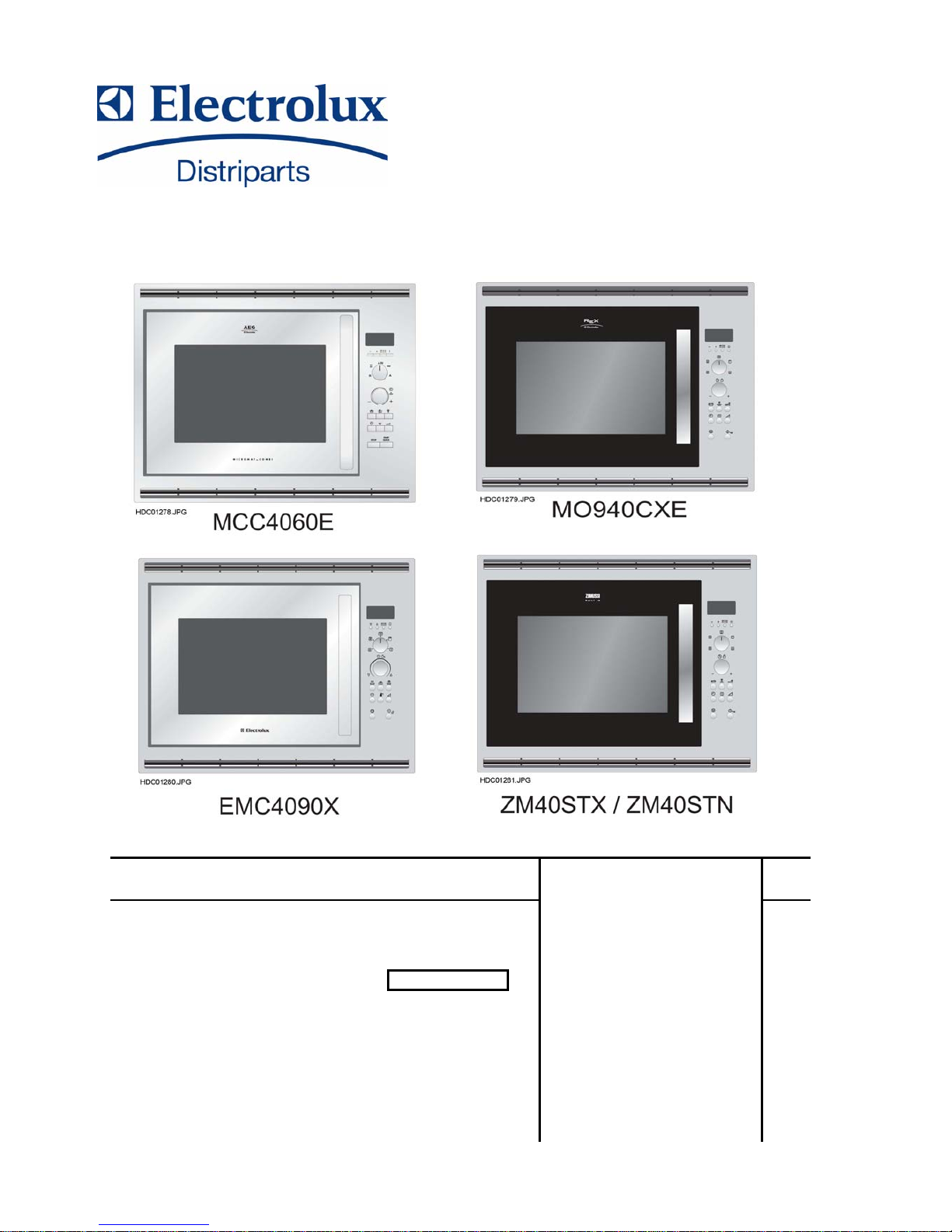
Microwave Oven
GRILL AND CONVECTION
MICROWAVE OVEN
(Micromat Combi)
MCC4060E
MO940CXE
EMC4090X
ZM40STX
ZM40STN

SOI 12.06 FV 2/43 599 37 42-75

SOI 12.06 FV 3/43 599 37 42-75
TABLE OF CONTENTS
CAUTION, MICROWAVE RADIATION....................................................................................................4
SERVICING / GENERAL INFORMATION ..............................................................................................5
PRODUCT SPECIFICATIONS ................................................................................................................6
APPEARANCE VIEW ..............................................................................................................................7
CONTROL PANEL...................................................................................................................................4
OPERATION SEQUENCE.....................................................................................................................10
FUNCTION OF IMPORTANT COMPONENTS .....................................................................................12
TROUBLESHOOTING GUIDE...............................................................................................................13
TEST PROCEDURES............................................................................................................................14
JOG CONTROL PANEL ASSEMBLY ....................................................................................................22
SERVICING............................................................................................................................................23
COMPONENT REPLACEMENT AND ADJUSTMENT PROCEDURE..................................................24
MICROWAVE MEASUREMENT............................................................................................................30
TEST DATA A GLANCE ........................................................................................................................31
SCHEMATIC DIAGRAMS......................................................................................................................32
PICTORIAL DIAGRAM ..........................................................................................................................33
SOI 12.06 FV 4/43 599 37 42-75
CAUTION
CAUTION
MICROWAVE RADIATION
DO NOT BECOME EXPOSED TO RADIATION FROM THE MICROWAVE GENERATOR OR
OTHER PARTS THAT CONDUCT MICROWAVE ENERGY.
GENERAL IMPORTANT INFORMATIONS
This Manual has been prepared to provide Service Engineers with Operation and Service Information.
It is recommended that service engineers carefully study the entire text of this manual, so they will be qualified
to render satisfactory customer service.
WARNING
Note: The parts marked "*" are used at voltage
more than 250V. (Schematic Diagrams).
WARNING
Never operate the oven until the following points are ensured.
(A) The door is tightly closed.
(B) The door and oven hinges are not defective.
(C) The door packing is not damaged.
(D) The door is not deformed or warped.
(E) There is not any other visible damage with the oven.
Servicing and repair work must be carried out only by trained
Service Engineers.
All the parts marked ”*” on schematic diagrams are used at
voltages more than 250V.
Removal of the outer wrap gives access to potentials above
250V.
If the Magnetron or/and the door assembly are damaged,
loosened or removed may cause undue microwave
exposure.
SOI 12.06 FV 5/43 599 37 42-75
SERVICING
WARNING TO SERVICE PERSONNEL
Microwave ovens contain circuitry capable of producing very high voltage and current.
Contact with the following parts will result in electrocution
High voltage capacitor, High Voltage transformer, Magnetron, High voltage rectifier assembly, High voltage
wires.
REMEMBER TO CHECK 3D
1) Disconnect the supply.
2) Door opened, and wedged open.
3) Discharge high voltage capacitor.
WARNING AGAINST THE CHARGE OF THE
HIGH VOLTAGE CAPACITOR
The high-voltage capacitor remains charged about
60seconds after the oven has been switched off.
Wait for 60 seconds and then short-circuit the
connection of the high-voltage capacitor (that is, of
the connecting lead of the high-voltage rectifier)
against the chassis with the use of an insulated
screwdriver.
It is recommended that wherever possible faultfinding is carried out with the supply disconnected. It
may in, some cases, be necessary to connect the
supply after the outer case has been removed, in this
event carry out 3D checks and then disconnect the
leads to the primary of the power transformer. Ensure
that these leads remain isolated from other
components and the oven chassis. (Use insulation
tape if necessary.) When the testing is completed
carry out 3D checks and reconnect the leads to the
primary of the power transformer.
REMEMBER TO CHECK 4R
1) Reconnect all leads removed from components
during testing.
2) Replace the outer case (cabinet).
3) Reconnect the supply.
4) Run the oven. Check all functions.
Microwave ovens should not be run empty. To test for
the presence of microwave energy within a cavity,
place a cup of cold water on the oven turntable, close
the door and set the power to HIGH and set the
microwave timer for two (2) minutes. When the two
minutes has elapsed (timer at zero) carefully check
that the water is now hot. If the water remains cold
carry out 3D checks and re-examine the connections
to the component being tested.
When all service work is completed, and the oven is
fully assembled, the microwave power output should
be checked and a microwave leakage test carried out.
When troubleshooting the microwave oven, it is
helpful to follow the Sequence of Operation in
performing the checks.
Many of the possible causes of trouble will require
that a specific test be performed. These tests are
given a procedure letter which will be found in the
"Test Procedure" section.
IMPORTANT:
If the oven becomes inoperative
because of a blown fuse F1 in the
monitored latch switch - monitor
switch - circuit, check the monitored
latch switch and monitor switch and
before replacing the fuse F1.
GENERAL INFORMATION
WARNING
THIS APPLIANCE MUST BE EARTHED
IMPORTANT
THE WIRES IN THIS MAINS LEAD ARE COLOURED IN ACCORDANCE WITH THE FOLLOWING
CODE:
GREEN-AND-YELLOW : EARTH
BLUE : NEUTRAL
BROWN : LIVE

SOI 12.06 FV 6/43 599 37 42-75
PRODUCT SPECIFICATIONS
SPECIFICATION
ITEM DESCRIPTION
Power Requirements 230 Volts / 50 Hertz / Single phase, 3 wire earthed
Microwave cooking 1.5kW Approx. 6.7A
Convection cooking 2.7kW Approx.12A
Grill cooking 2.7kW Approx.12A
Micro and Grill ................... 2.8 kW Approx. 12.7 A
Power Consumption
Dual cooking
Micro and Convection ........ 2.8 kW Approx. 12.7 A
Power Output
900W watts nominal of RF microwave energy (measured by way of IEC 60705)
Operating frequency of 2450 MHz
Grill heating element Power
Output
1300 W (650 W x 2)
Convection heating element
Power Output
1450 W
Case Dimensions Width 550mm Height 368mm Depth 537mm
Cooking Cavity Dimensions Width 375mm Height 272mm
Turntable diameter 325mm
Touch Control System
Clock (1.00-12.59 or 0.00-23.59) / Timer (0 - 99 minutes 30 sec.)
Microwave Power for Variable Cooking
Repetition Rate;
100% (HIGH) ....... Full power throughout the cooking time
70% (MEDIUM HIGH) .................... approx. 70% of FULL Power
50% (MEDIUM)............................... approx. 50% of FULL Power
30% (MEDIUM LOW)...................... approx. 30% of FULL Power
10% (LOW) ..................................... approx. 10% of FULL Power
Convection temperature control range
250°C, 230°C, 220°C, 190°C, 180°C, 160°, 130°C, 100°C, and 40°C
Control Complement
1. COOKING indicator
2. START indicator
3. GRILL indicator
4. CONVECTION indicator
5. MICROWAVE indicator
6. INFORMATION indicator
7. INFORMATION button
8. LANGUAGE button
9. COOKING MODE knob
for microwave cooking
10. TIME/WEIGHT knob
rotate the knob to enter to enter
either the cooking/defrosting time
or weight of food..
11. AUTO COOK button
12. COOK FROM FROZEN button
13. AUTO DEFROST button
14. MICROWAVE POWER LEVEL button
15.
+ START/QUICK button
16. STOP button
17. CONVECTION button
18. CLOCK SETTIN button
19. LESS/MORE button
for microwave cooking with GRILL
for microwave cooking with CONVECTION
for GRILL
for CONVECTION
Net weight
Approx. 23 kg
SOI 12.06 FV 7/43 599 37 42-75
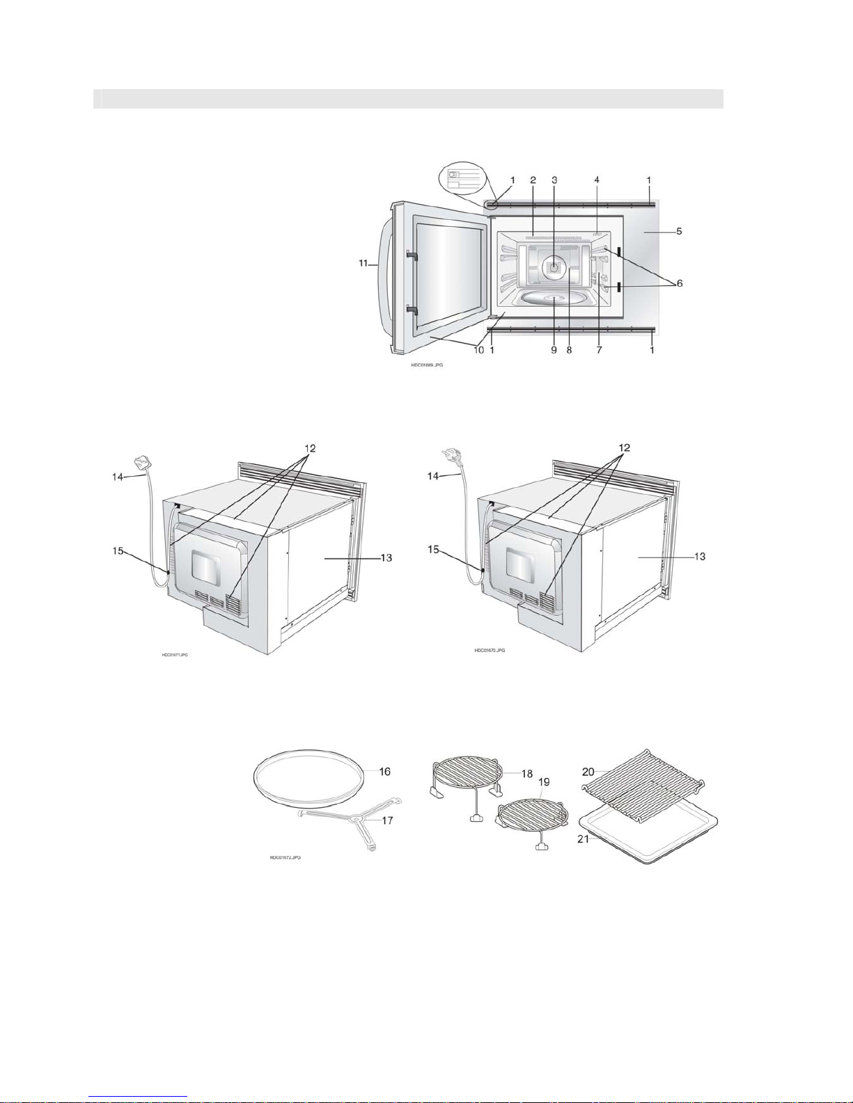
APPEARANCE VIEW
OVEN
1. Fixing points (4 points)
2. Grill heating element
3. Convection heating element
4. Oven lamp
5. Control panel
6. Shelf runners
7. Waveguide cover
8. Oven cavity
9. Coupling
10. Door seals and sealing surfaces.
11. Door opening handle
12. Air-vent / intake opening
13. Outer cover
14. Power cord
15. Power supply cord support clip.
U.K . BACK VIEW
EUROPEAN BACK VIEW
16. Turntable
17. Turntable support
18. High Rack
19. Low Rack
20. Square shelf
21. Square tray
SOI 12.06 FV 8/43 599 37 42-75
CONTROL PANEL
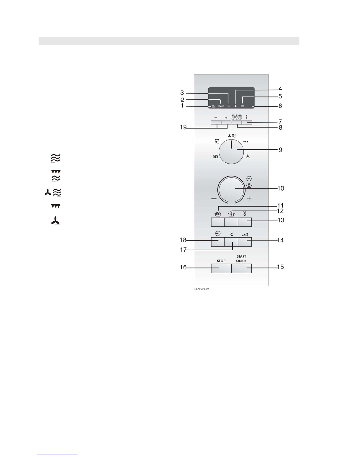
MCC4090E
Digital display and indicators:
1. COOKING indicator
2. START indicator
3. GRILL indicator
4. CONVECTION indicator
5. MICROWAVE indicator
6. INFORMATION indicator
Operating keys:
7. INFORMATION button
8. LANGUAGE button
9. COOKING MODE knob
for microwave cooking
for microwave cooking with GRILL
for microwave cooking with CONVECTION
for GRILL
for CONVECTION
10. TIME/WEIGHT knob
rotate the knob to enter either the cooking/defrosting
time or weight of food.
11. AUTO COOK button
12. COOK FROM FROZEN button
13. AUTO DEFROST button
14. MICROWAVE POWER LEVEL button
15. START/QUICK button
16. STOP button
17. CONVECTION button
18. CLOCK SETTING button
19. LESS/MORE button
SOI 12.06 FV 9/43 599 37 42-75
CONTROL PANEL
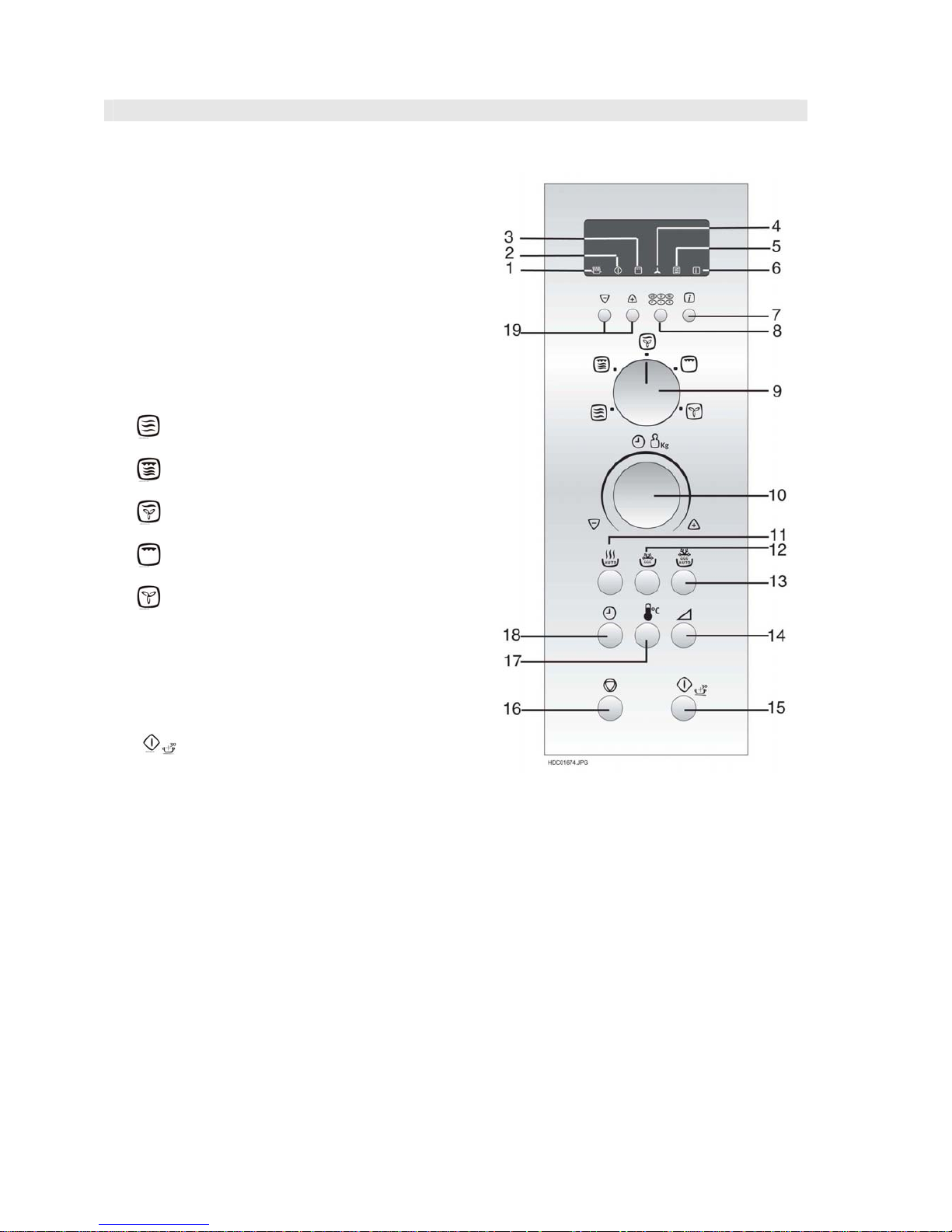
EMC4090X
Digital display and indicators:
1. COOKING indicator
2. START indicator
3. GRILL indicator
4. CONVECTION indicator
5. MICROWAVE indicator
6. INFORMATION indicator
Operating keys:
7. INFORMATION button
8. LANGUAGE button
9. COOKING MODE knob
for microwave cooking
for microwave cooking with GRILL
for microwave cooking with CONVECTION
for GRILL
for CONVECTION
10. TIME/WEIGHT knob
rotate the knob to enter either the cooking/defrosting
time or weight of food.
11. AUTO COOK button
12. COOK FROM FROZEN button
13. AUTO DEFROST button
14. MICROWAVE POWER LEVEL button
15.
START button
16. STOP button
17. CONVECTION button
18. CLOCK SETTING button
19. LESS/MORE button
SOI 12.06 FV 10/43 599 37 42-75
CONTROL PANEL
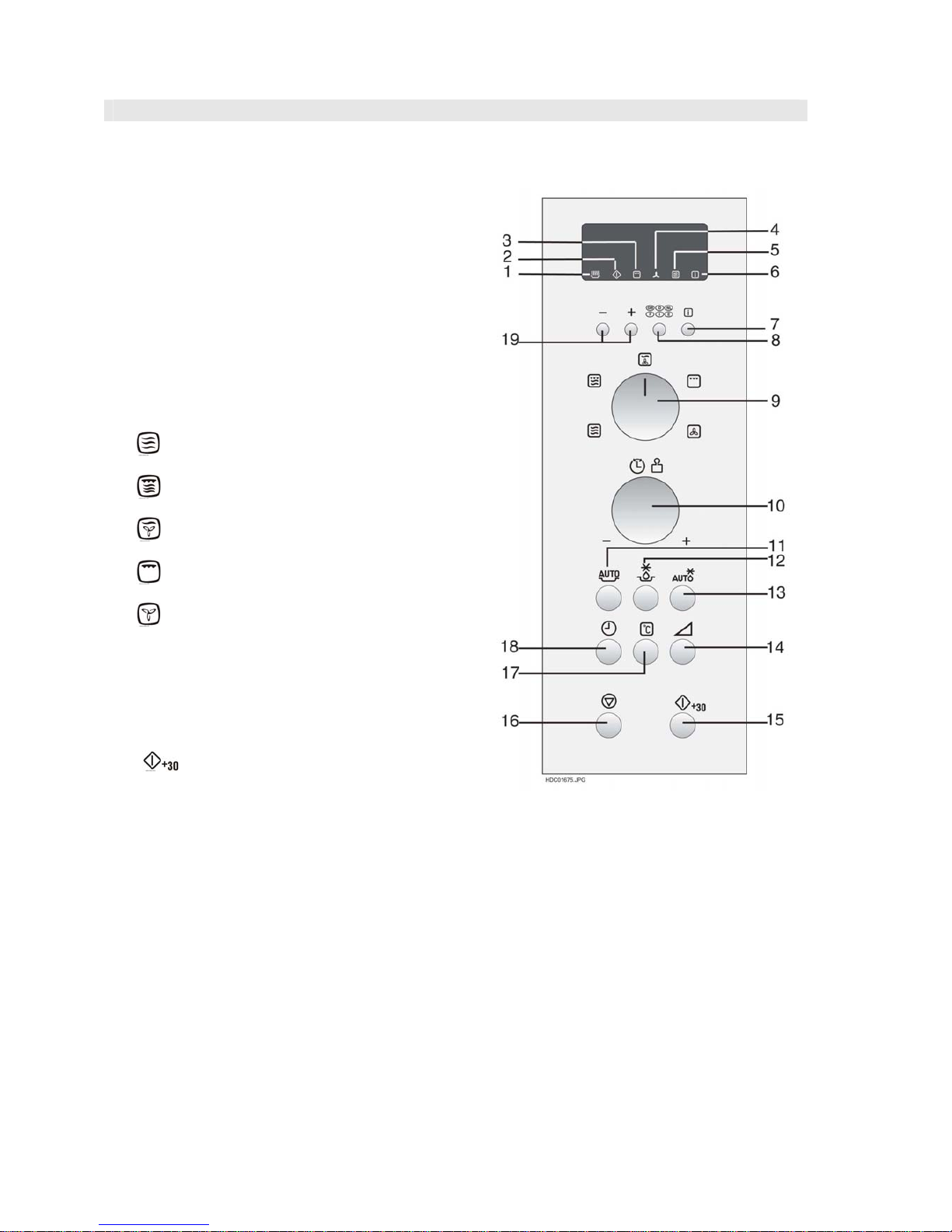
MO040CXE ZM4060STX
ZM4090X ZM4090STN
Digital display and indicators:
1. COOKING indicator
2. START indicator
3. GRILL indicator
4. CONVECTION indicator
5. MICROWAVE indicator
6. INFORMATION indicator
Operating keys:
7. INFORMATION button
8. LANGUAGE button
9. COOKING MODE knob
for microwave cooking
for microwave cooking with GRILL
for microwave cooking with CONVECTION
for GRILL
for CONVECTION
10. TIME/WEIGHT knob
rotate the knob to enter either the cooking/defrosting
time or weight of food.
11. AUTO COOK button
12. COOK FROM FROZEN button
13. AUTO DEFROST button
14. MICROWAVE POWER LEVEL button
15.
START button
16. STOP button
17. CONVECTION button
18. CLOCK SETTING button
19. LESS/MORE button
SOI 12.06 FV 11/43 599 37 42-75
OPERATION SEQUENCE
OFF CONDITION
Closing the door activates the monitored latch switch and the stop switch.
IMPORTANT
When the oven door is closed, the contacts COM - NC of the monitored switch must be open.
When the microwave oven is plugged in a wall outlet (230V / 50Hz), the line voltage is supplied to the noise
filter.
( Figure O-1 )
1. The control unit is not energized. The display shows nothing (Fig. O-1 (a)).
2. Open the door. The contacts (COM-NC) of the monitored latch switch are closed and the control unit is
energized. Then contacts of relays RY1
and RY5 are closed, and the oven lamp will light and the display will
show "SELECT LANGUAGE" in 5 languages. (Fig. O-1(b)).
NOTE: Once the language is selected using the LANGUAGE key, the display will show "ENERGY
SAVE MODE TO GO OUT OF ENERGY SAVE MODE SET CLOCK" when the oven is plugged in.
3. Close the door. The contacts (COM-NC) of the monitored latch switch are opened and the contacts of relay
RY1
are opened and the oven lamp will be turned off. The display will show " . 0". (Fig. O-1(c)).
NOTE: Energy save mode
1. If the oven has not been used for more than 3 minutes, the contacts of the relay RY5
will be opened and the
control unit will be not energized. Open and close the door, the control unit will resume.
2. If the clock is set, this energy save mode does not work.
3. If the display shows different messages from ENERGY SAVE MODE, the oven may be set in demo mode.
Close the door, see operation manual to cancel demo mode.
MICROWAVE COOKING CONDITION
HIGH COOKING
Enter a desired cooking time by touching the TIME keys and start the oven by touching START key.
Function sequence (Figure O-2)
CONNECTED COMPONENTS RELAY
Oven lamp, Turntable motor RY1
Power transformer RY3
Fan motor RY6
1. The line voltage is supplied to the primary winding of the high voltage transformer. The voltage is converted to
about 3.3 volts A.C. output on the filament winding and high voltage of approximately 2000 volts A.C. on the
secondary winding.
2. The filament winding voltage (3.3 volts) heats the magnetron filament and the high voltage (2000 volts) is sent
to the voltage doubling circuit, where it is doubled to negative voltage of approximately 4000 volts D.C..
3. The 2450 MHz microwave energy produced in the magnetron generates a wavelength of 12.24 cm. This
energy is channelled through the waveguide (transport channel) into the oven cavity, where the food is
placed to be cooked.
4. When the cooking time is up, a single tone is heard and the relays RY1 + RY3 + RY6
go back to their
home position. The circuits to the oven lamp, high voltage transformer, fan motor and turntable motor are cut
off.
5. When the door is opened during a cook cycle, the switches come to the following condition.
CONDITION
SWITCH
CONTACT
DURING
COOKING
DOOR OPEN
(NO COOKING)
COM-NO Closed Opened
Monitored latch switch
COM-NC Opened Closed
Stop switch COM-NO Closed Open
COM-NO Closed Opened
Monitor switch
COM-NC Opened Closed
The circuits to the high voltage transformer is cut off when the contacts of relay RY2, and the contacts (COM-NO) of
the monitored latch switch SW1
and the monitor switch SW3 are made open. The circuit to the fan motor is cut off
when the relay RY6
is made open.
SOI 12.06 FV 12/43 599 37 42-75
OPERATION SEQUENCE
The circuit to the turntable motor is cut off when the contacts (COM-NO) of the monitored latch switch SW1 are
made open. The oven lamp remains on even if the oven door is opened after the cooking cycle has been
interrupted, because the relay RY1
stays closed. Shown in the display is the remaining time.
6. MONITOR SWITCH CIRCUIT
The monitor switch SW3
is mechanically controlled by oven door, and monitors the operation of the
monitored latch switch SW1
.
6-1 When the oven door is opened during or after the cycle of a cooking program, the monitored latch switch SW1
,
and stop switch SW2
must open their contacts (COM-NO) first. And the contacts (COM-NC) of the monitored
latch switch SW1
are made closed. After that the contacts (COM - NC) of the monitor switch SW3 can be
closed and the contacts (COM-NO
) of monitor switch SW3 are made open.
6-2 When the oven door is closed, the contacts (COM - NC
) of the monitor switch SW3 must be
opened and the contacts (COM - NO
) of monitor switch SW3 must be closed. After that the contacts
(COM - NO
) of the monitored latch switch SW1 and stop switch SW2 are made closed. And the contacts
(COM - NC
) of the monitored latch switch SW1 are made open .
6-3 When the oven door is opened and the contacts (COM - NO
) of the monitored latch switch SW1 remain
closed, the fuse F2
F8A will blow. Because the relay RY1 and monitor switch SW3 are closed and a short
circuit is caused.
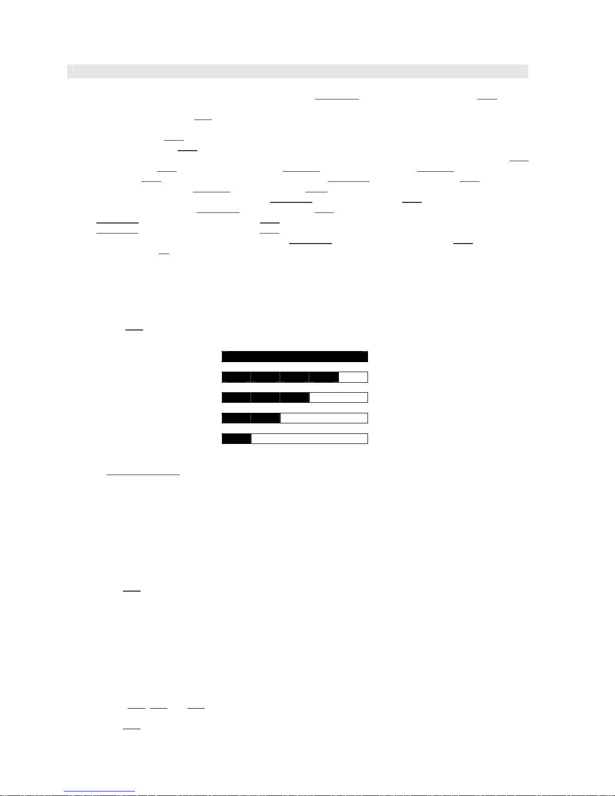
HIGH, MEDIUM HIGH, MEDIUM, MEDIUM LOW, LOW COOKING
When the microwave oven is preset for variable cooking power, the line voltage is supplied to the high voltage
transformer intermittently within a 32-second time base through the relay contact which is coupled with the currentlimiting relay RY2
. The following levels of microwave power are given.
32 sec. ON
100% (HIGH) 100%
24 sec. ON
70% (MEDIUM HIGH) Approx. 70%
18 sec. ON
50% (MEDIUM) Approx. 50%
12 sec. ON
30% (MEDIUM LOW) Approx. 30%
6 sec. ON
10% (LOW) Approx. 10%
NOTE: The ON/OFF time ratio does not exactly correspond to the percentage of microwave power, because
approx. 3 seconds
are needed for heating up the magnetron filament.
GRILL COOKING CONDITION
TOP GRILL (Figure O-3a)
In this condition the food is cooked by grill heating element energy. Programme the desired cooking time by turing
the "TIME/WEIGHT" knob and the select knob to “GRILL”. When the "START" button is pressed, the following
operations occur:
1. The numbers on the digital read-out start the count down to zero.
2. The oven lamp, cooling fan motor and turntable motor are energized.
3. The relay RY3
is energized and the main supply voltage is applied to the top grill heatig elements.
4. Now the food is cooked by the top grill heating elements.
NOTE: The grill cooking condition will be carried out continuously until the temperature of the oven cavity rise
to 220°C.
CONVECTION COOKING CONDITION (Figure O-4)
PRE-HEATING (by 40°C - 130°C)
Turn select knob to CONVECTION.
Programme the desired convection temperature of 40°C - 130°C by pressing the CONVECTION button. When the
START button is pressed, the following operations occur:
1. The relays RY1
, RY6 and RY7 are energized, the oven lamp, turntable motor, fan motor and convection motor
are turned on.
2. The relay RY4
is energized and the main supply voltage is applied to the convection heating element.
3. After the temperature of oven cavity rises to the selected one, the oven will continue to turn the convection
heating element on and off to maintain the temperature for 30 minutes.

SOI 12.06 FV 13/43 599 37 42-75
OPERATION SEQUENCE
PRE-HEATING (by 160°C - 250°C)
Turn select knob to CONVECTION
Programme the desired convection temperature of 160°C - 250°C by pressing the CONVECTION button.
When the START button is pressed, the following operations occur:
1. The relays RY1
, RY6 and RY7 are energized, the oven lamp, turntable motor, fan motor and convection
motor are turned on.
2. The relay RY4
and RY3 are is energized and the main supply voltage is applied to the convection heating
element and the grill heating elements.
3. After the temperature of oven cavity rises to the selected one, the oven will continue to turn the convection
heating element on and off to maintain the temperature for 30 minutes. And simultaneously the grill
heating element will be operated at 10% power output.
CONVECTION COOKING (by 250°C)
Programme the cooking time by turning the timer vari knob. And then programme the convection temperature of
250°C by pressing the CONVECTION button. When the START button is pressed, the following operations occur:
1. The relays RY1
, RY6 and RY7 are energized, the oven lamp, turntable motor, fan motor and convection motor
are turned on.
2. The relay RY4
and RY3 are energized and the main supply voltage is applied to the convection heating
element and the grill heating elements.
3. The oven will continue to turn the convection heating element on and off to maintain the temperature for the
programmed cooking time. And simultaneously the grill heating elements will be operated at 10% power output.
CONVECTION COOKING (by 40°C - 230°C)
Programme the cooking time by turning the timer vari knob. And then programme the desired convection
temperature of 40°C 230°C by pressing the CONVECTION button. When the START button is pressed, the
following operations occur:
1. The relays RY1
, RY6 and RY7 are energized, the oven lamp, turntable motor, fan motor and convection motor
are turned on.
2. The relay RY4
is energized and the main supply voltage is applied to the convection heating element.
3. The oven will continue to turn the convection heating element on and off to maintain the temperature for the
programmed cooking time.
DUAL COOKING CONDITION
MICROWAVE AND CONVECTION (Figure O-5a)
Programme the desired cooking time by turning the select knob to MICROWAVE and CONVECTION. Select the
microwave power level by pressing the MICROWAVE POWER LEVEL button. And select the convection
temperature by pressing the CONVECTION button.
NOTE: The 100% microwave power level can not be selected.
When the + 1min
/ START button is pressed, the following operations occur:
1. The numbers on the digital read-out start the count down to zero.
2. The oven lamp, fan motor, turntable motor and convection motor are energized.
3. The relay RY4
will be energized and the main supply voltage is applied to the convection heating element.
4. The relay RY2
is energized and the microwave energy is generated by magnetron.
5. Now, the food is cooked by microwave and convection energy simultaneously.
MICROWAVE AND TOP GRILL (Figure O-5b)
Programme the desired cooking time by turning the select knob to MICROWAVE and TOP GRILL. Select the
microwave power level by pressing the MICROWAVE POWER LEVEL button. When the START button is pressed,
the following operations occur:
1. The numbers on the digital read-out start the count down to zero.
2. The oven lamp, fan motor and turntable motor are energized.
3. The relay RY3
is energized and the main supply voltage is applied to the top grill heateing elements.
4. The relay RY2
is energized and the microwave energy is generated by magnetron.
5. Now the food is cooked by microwave and grill simultaneously.
 Loading...