

Electrolux ZHTAROW, EHTAROW60, ZHTAROW60, EHTAROW, OHTAROW60 User Manual
...
ENGLISH
GB CONTENTS
A GENERAL RECOMMENDATIONS.......................................................... Page 4
A1 HANDLING......................................................................................................................Page 4
A2 UNPACKING....................................................................................................................Page 4
A3 DISPOSAL.......................................................................................................................Page 4
A4 TECHNICAL DATA ..........................................................................................................Page 5
B INSTRUCTIONS FOR THE INSTALLER/MAINTENANCE PERSON..... Page 7
B1 WATER CONNECTION...................................................................................................Page 7
B2 ELECTRICAL CONNECTION .........................................................................................Page 7
B3 WARNING MESSAGES DISPLAYED ON THE CONTROL PANEL................................Page 8
B4 DETERGENT/RINSE-AID DISPENSERS AND SETTINGS............................................Page 9
B5 SETTING THE DISPENSERS.........................................................................................Page 10
B6 MAINTENANCE...............................................................................................................Page12
C INSTRUCTIONS FOR THE USER........................................................... Page 13
C1 STARTING.......................................................................................................................Page 14
C2 WASH CYCLES...............................................................................................................Page14
C3 OPERATION....................................................................................................................Page 14
C4 END OF WORK AND DAILY CLEANING.......... ... ... .... ... ... ... .... ... ... ... ... .... ... ... ... .... ... .......Page 15
C5 WARNING MESSAGES DISPLAYED ON THE CONTROL PANEL................................Page 16
C6 RESIDUAL RISKS...........................................................................................................Page 16
D TROUBLESHOOTING............................................................................. Page 18
3
WARNING
A GENERAL RECOMMENDATIONS
PE
PP
PS
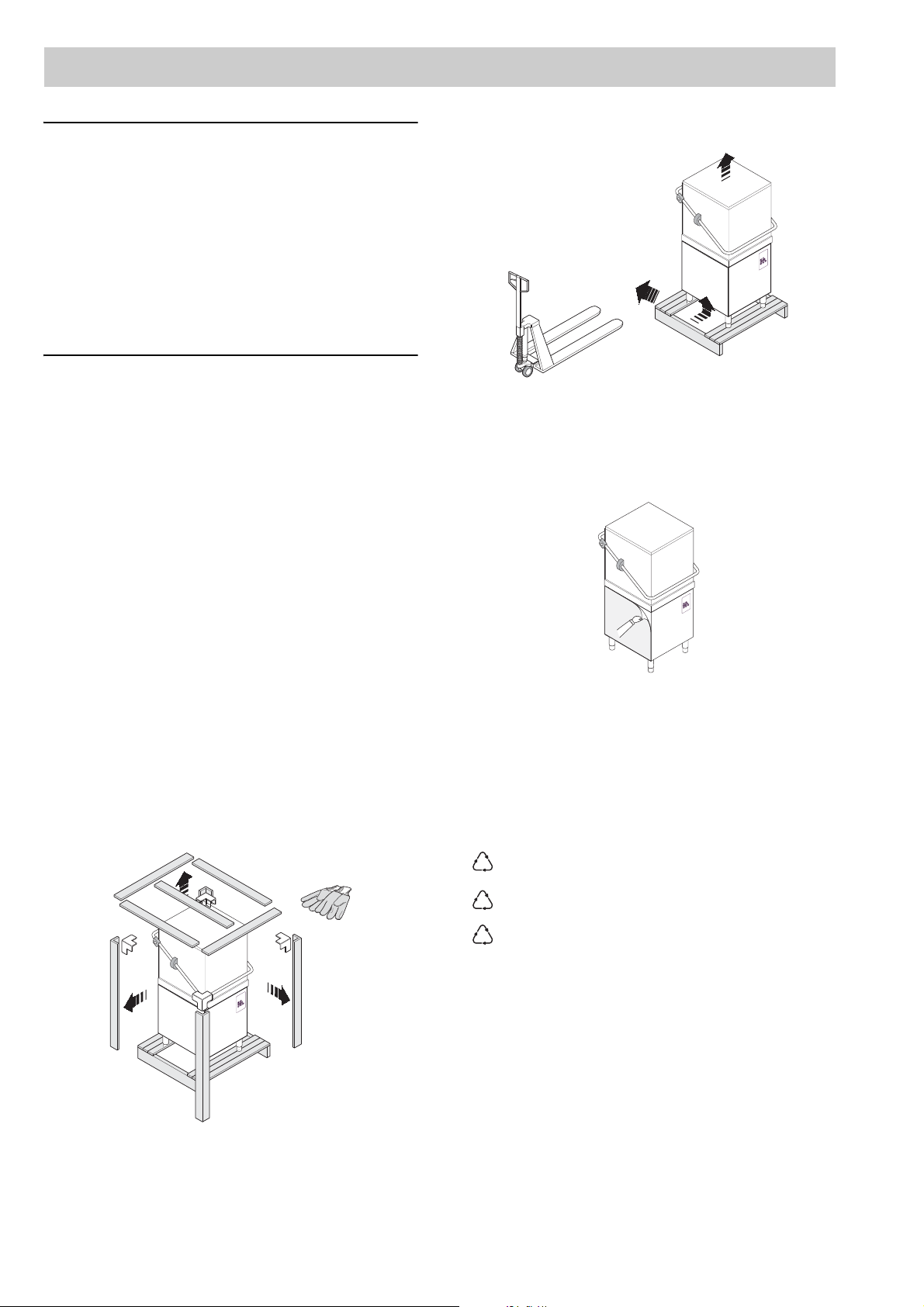
Lift the appliance using a lift truck, remove the base
CAREFULLY READ THE INSTALLATION, OPERATING AND MAINTENANCE INSTRUCTIONS BEFORE
INSTALLING THIS APPLIANCE. INCORRECT
INSTALLATIONS, ADAPTATIONS OR ALTERATIONS COULD CAUSE DAMAGE TO PROPERTY
OR INJURY TO PERSONS. MALICIOUS DAMAGE,
DAMAGE DUE TO NEGLIGENCE, OR TO FAILURE
TO COMPLY WITH INS TRUCTIONS AND REGULATIONS, OR TO INCORRECT CONNECTIONS OR
UNAUTHORISED TAMPERING INVALIDATE ANY
WARRANTY AND RELIEVE THE MANUFACTURER
OF ALL LIABILITY.
and position the appliance where it is to be installed.
1. Carefully read this instructions booklet, as it contains important advice for safe installation, operation and maintenance.
Keep this booklet to hand in a safe place for future
reference by other operators.
2. Installation should be carried out by qualified
engineers, in accordance with current regulations and with the manufacturerís instructions.
3. The appliance should only be used by persons specifically trained in this operation.
4. Switch off the appliance in the event of failure or
malfunctioning.
Only have the appliance repaired by a service centre
authorised by the manufacturer and ask for original
spare parts.
A1 HANDLING
Use suitable means to move the appliance: a lift truck
or fork pallet trucks (the forks should reach more than
halfway beneath the appliance).
A2 UNPACKING
Wear protective gloves to unpack.
Figure 2
Remove the protective film and ensure that the packaging material is disposed of correctly in compliance
with the regulations in force in the country wh ere the
product is to be used.
Figure 3
A3 DISPOSAL
All the packaging materials are environment friendly.
They may be kept without danger, recycled or burned
in a special waste incineration plant. Recyclable plastic
components are marked as follows:
4
polyethylene external wrapping film,
instruction bag.
polypropylene top packaging panels,
straps.
polystyrene foam protective
surround elements.
Wood and cardboard components may be disposed of
according to local regulations in force. Appliances that
have reached the end of their service life should be suitably disposed of. The appliance should be dismantled
according to regulations in force. All metal parts are in
stainless steel (AISI 304) and are removable. Plastic
parts are marked with the symbol of the material.
Figure 1
ENGLISH
A4 TECHNICAL DATA
MODEL EHTAROW / ZHTAROW /
OHTAROW
Supply voltage:
• three-phase version V 400...415- 3N~ 220...240- 3~ N~
- convertible to V 220...240- 3~ 400...415- 3
- convertible to V 220...240- 1N~ (**) 220...240- 1N~ (**)
Frequency Hz 50 60
Max. power input (three-phase version) kW 15,9 15,9
Max. power input (single-phase version) kW 9,9 9,9
Boiler heating elements kW 6,0 + 6,0 (**) 6,0 + 6,0 (**)
Tank heating elements kW 3,0 3,0
Water supply pressure kPa [bar] 50...700 [0,5...7] 50...700 [0,5...7]
Water supply temperature °C 10 ... 60 10 ... 60
Water supply hardness °fH [°dH ] 14 [8] max 14 [8] max
Rinse cycle water consumption l 3,0 3,0
Boiler capacity l 12 12
Tank capacity l 42 42
Standard cycle time:
- Thermal label mode sec. 77-90-150 77-90-150
- High productivity mode sec. 54-90-150 54-90-150
Legal noise level dB(A) <68 <68
Protection rating IPX4 IPX4
Net weight kg 98 98
Power supply cable H07RN-F H07RN-F
Supply cord diameter (min - max value) mm 18-25 18-25
EHTAROW60 / ZHTAROW60 /
OHTAROW60
(**) = Reduce the power of the boiler from 12 kW to 6kW as shown in the circuit diagram.
Table 1
400..415 V 3N 220...240 V 3 220…240 V 1N
CSCSCS
9,9 kW - - - - 3X10 60 A 1P+N
15,9 kW 5X6 40 A 3P+N 4X10 60 A 3P - -
C = Power supply cable
S = On/Off switch
Table 2
Standard cycle time may vary should the inlet water temperature be differen t from that indicated above.
5
1515
636
748
55
236
543
55
327
215
132
39
833
126
329
329
329
138
65
658
833
410
1970
152
56
404
559
167
200
875
140
S2
650
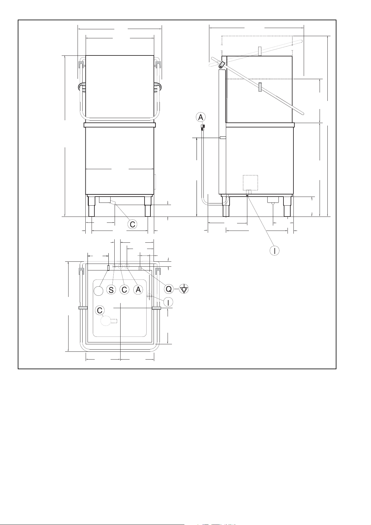
Figure 4
Legend Figure 4
A - Water inlet pipe with Ø 3/4” G fittings
C - Outlet pipe Øi 40 mm (^) – Øi 18 mm (*).
I - Power supply
S - Pipe inlet for detergents
S2 - Solid detergent injector (only ”OHTAROW / OHTAROW60” vers ions)
Q - Unipotential screw
(^) - Only for model with free-fall drainage
(*) - Only for model with drain pump
6
ENGLISH
ATTENTION
B
Model RT10 ED
PNC 9CGX 531300 05 Ser.N .123000001
AC 400V 3N 50Hz
Power Boiler 16500w
Power Tank 7500w
Power Max 26800w
Made in EEC
Model RT10 ED
PNC 9CGX531300 05
Ser.N .123000001
!
A
C 400....
1
11
10
9
8
7
6
5
4
3
2
12
!
INSTRUCTIONS FOR THE INSTALLER/MAINTENANCE PERSON
Install a disconnecting switch with a capacity at
least equal to that given in the technical data table,
a 30mA residual current circuit breaker and an
overcurrent device (magnetothermal cut-out with
manual reset or fuse) between the appliance and
the mains power outlet.
The chosen device must be lockable in the open
position in case of maintenance.
Do not place the dishwas h er ne ar direct heat sources such as fryers, ovens, hot-plates, etc.
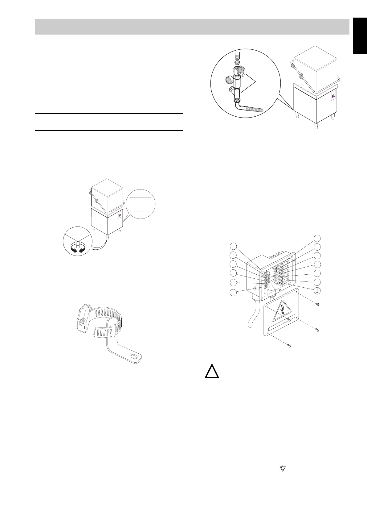
Figure 7
RATING PLATE
The rating plate contains identification and technical
data and is located on the right-hand side panel of the
appliance (Figure 5).
Figure 5
B1 WATER CONNECTION
• The appliance must be fixed to the ground using
the two clamps supplied (Figure 6).
• Check that the dynamic water supply pressure,
measured between the ap pliance and the main, is
between 50 and 700 kPa (test while dishwasher
tank or boiler is filling with water).
If the pressure is too high, fit a suitable pressure reducer on the inlet pipe.
Connect the waste outlet pipe “C” (Figure 4) to the
main drain pipe, fitting a trap, or place the outlet pipe
over an S trap set into the floor.
B2 ELECTRICAL CONNECTION
Figure 6
• Position the dishwasher and level the appliance by
turning the feet (Figure 5).
• Accessing the appliance bottom panel.
• Fit the clamps on feet as shown in supp lied technical sheet.
• Screw the appliance steadily to the ground using
hole clamps.
• Connect the appliance water supply pipe “A”
(Figure 4) to the mains, fitting a cut-off cock, the filter provided and a pressure gauge between the
appliance and the mains (Figure 7).
Figure 8
CAUTION
THE EARTH AND ELECTRICAL CONNECTIONS SHOULD BE IN COMPLIANCE
WITH NATIONAL REGULATIONS.
• Before carrying out the electrical connection, check that
the voltage and frequency on the appliance rating plate
correspond to those of the mains electricity supply.
• The earth wire at the terminal end must be longer
(max. 20 mm) than the phase wires.
• Connect the earth wire of the power supply cable to
an efficient earth clamp. The appliance must also
be included in a unipotential system, the connection being made through the screw “Q” (Figure 4)
marked with the symbol “ ”. The unipotential wire
must have a cross section of 10 mm
2
.
7
 Loading...