

Page 1
PV100 SERIES
ELECTRONICALLY CONTROLLED
PROPORTIONAL VALVES
INSTRUCTION
SHEET
M2160-0204
Unpacking
Remove the Packing List and verify that you have
received all equipment, including a PV100 Series
proportional valve, and instruction sheet. If you
have any questions about the shipment, please call
the Customer Service Department at 1-800-622-2378
or 203-359-1660. We can also be reached on the
Internet at www.omega.com
e-mail: cservice@omega.com
When you receive the shipment, inspect the
container and equipment for signs of damage. Note
any evidence of rough handling in transit.
Immediately report any damage to the shipping
agent.
General Description
The OMEGA®PV100 Series Electronically
Controlled Proportional Valves are two-way
normally closed valves. When the valve is
deenergized, pressure is sealed off by the force of
the plunger assembly return spring and the seal in
the plunger assembly. When the valve is energized,
the plunger assembly moves upward, permitting
flow through the valve. The valve is direct acting.
Higher current or control signal results in more
plunger movement and more flow.
Installation
Port Identification
Apply inlet pressure to the port marked “P”.
Mounting Position and Pressure Limits
Valves can be mounted directly on piping and are
designed to operate in any position. Two 8-32
tapped mounting holes 1⁄4” deep are provided in the
base of the body. Line pressure must not exceed the
nameplate rating.
Piping
Remove closures from ports and connect pressure
lines to proper ports. All valves have 1⁄8" NPTF
fittings. Tightening torque on the 1⁄8" NPT should
not exceed 38 in-lbs.
Media Filtration
Filtration of air lines is recommended. Install the
filter in the inlet side as close to the valve as
possible. These valves have no sliding fits and are
generally not sensitive to a small amount of foreign
material, however, they do contain soft rubber
inserts. Dirt or foreign material in the media may
cause excessive leakage, excessive wear, or in
exceptional cases, malfunction.
Electrical Connection
Electrical supply must conform to nameplate
rating. Connect coil leads to DC voltage using
standard electrical practice.
Black wire Common Ground
(to Power Supply and Control)
Red wire (+) DC Positive Power Supply
Gray wire (+) Control Signal
If the coil housing is located in an inconvenient
position, the housing nut can be loosened and the
housing rotated to any convenient position. Then
re-tighten the nut to 13 to 35 in-lbs.
Coil Housing Temperature
Standard valves are supplied with coils designed
for continuous duty service. Normal free space
must be provided for proper ventilation. When coil
is energized continuously for long periods of time,
the coil housing will become hot 54 to 71°C (130 to
160°F). The coil is designed to operate continuously
under these conditions. Any excessive heating will
be indicated by smoking and/or odor of burning
insulation.
Lubrication
Lubrication is not required.
Maintenance Instructions
Valves are calibrated at the factory and should not
be disassembled by the user.
Page 2
Available Models
*Specify Control Signal: MA for 4-20 MADC
5V for 0-5 VDC
10V for 0-10 VDC
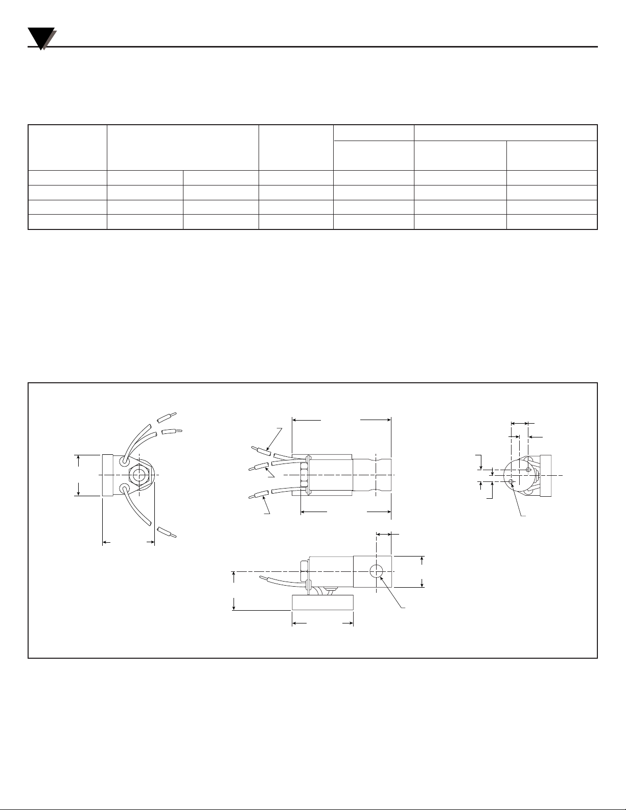
Dimensions
PV100 Series Proportional Valves
Flow Ranges, SCCM
Model Orifice Maximum At Maximum At
Number Millimeters Inches
C
v Pressure Pressure 10 PSI
PV101-(*) .80 1/32 0.02 200 PSI 0-50,000 0-8,000
PV102-(*) 1.19 3/64 0.045 100 PSI 0-65,000 0-17,000
PV103-(*) 1.59 1/16 0.08 60 PSI 0-75,000 0-30,000
PV104-(*) 1.98 5/64 0.12 40 PSI 0-80,000 0-45,000
35.05 ±0.38
(1.38 ±0.015)
45.47 ±0.51
(1.79 ±0.02)
84.07 ±1.0
(3.31 ±0.04)
10.1
(0.396)
5.0
(0.198)
RED
POSITIVE
BLACK
COMMON
GRAY
CONTROL
ELECTRICAL TERMINATIONS
RED - DC POWER SUPPLY (+)
GRAY - CONTROL SIGNAL (+)
BLACK - COMMON (TO POWER
SUPPLY AND CONTROL SIGNAL)
74.45 ±0.51
(3.01 ±0.02)
50.80 ±0.51
(2.00 ±0.02)
15.0
(0.59)
7.5
(0.295)
13.46
(0.53)
P
32.51
(1.28)
26.92 DIA.
(1.06 DIA.)
1/8 NPT
2 PLC'S
#8-32 NC-2B TH'D
2 PLC'S
DIMENSIONS mm (inches)
2
Page 3

PV100 Series Proportional Valves
3
0 102030 405060 708090100
100
85
15
ZERO OFFSET POINT
(POINT WHERE FLOW BEGINS)
TYPICALLY BETWEEN 30-40%
OF CONTROL SIGNAL DEPENDING
ON ACTUAL SYSTEM PRESSURE.
LINEAR
(Y) CONTROL
RANGE
% FLOW
PROPORTIONAL VALVE FLOW CURVE
% CONTROL SIGNAL
(X)
0
Specifications
Valve Type: 2-Way Normally Closed
Wetted Parts: Stainless Steel with Viton Seals
Power: 12-24 VDC
Power Consumption: 7 Watts Maximum
Control Signals: 0-5 VDC, 0-10 VDC, 4-20 MADC
Ambient Temperature Range: -10 to 50°C
(14 to 122°F)
Media Temperature Range: -18 to 82°C
(0 to 180°F)
Linear Control Range: 15-85% of Full Flow
Response Time for Complete Cycle
Off - Full Open - Off: 40 msec @ 0 pressure
100 msec @ maximum pressure
Repeatability: ±5% when in operating linear control range
Electrical Connection: 18" color-coded lead wires
Wiring: Red DC Power Supply
Gray Control Signal (+)
Black Common (to Power and Control)
Pressure Connections:
1
⁄8" NPTF
Enclosure: General Purpose, NEMA-1
Page 4

It is the policy of OMEGA Engineering, Inc. to comply with all worldwide safety and EMC/EMI regulations that apply. OMEGA is constantly pursuing certification of its
products to the European New Approach Directives. OMEGA will add the CE mark to every appropriate device upon certification.
The information contained in this document is believed to be correct, but OMEGA accepts no liability for any errors it contains, and reserves the right to alter specifications without notice.
WARNING: These products are not designed for use in, and should not be used for, human applications.
WARRANTY/DISCLAIMER
OMEGA ENGINEERING, INC. warrants this unit to be free of defects in materials and workmanship for a period of 13 months from date of purchase.
OMEGA’s WARRANTY adds an additional one (1) month grace period to the normal one (1) year product warranty to cover handling and
shipping time. This ensures that OMEGA’s customers receive maximum coverage on each product.
If the unit malfunctions, it must be returned to the factory for evaluation. OMEGA’s Customer Service Department will issue an Authorized Return (AR)
number immediately upon phone or written request. Upon examination by OMEGA, if the unit is found to be defective, it will be repaired or replaced
at no charge. OMEGA’s WARRANTY does not apply to defects resulting from any action of the purchaser, including but not limited to mishandling,
improper interfacing, operation outside of design limits, improper repair, or unauthorized modification. This WARRANTY is VOID if the unit shows
evidence of having been tampered with or shows evidence of having been damaged as a result of excessive corrosion; or current, heat, moisture or
vibration; improper specification; misapplication; misuse or other operating conditions outside of OMEGA’s control. Components in which wear is not
warranted, include but are not limited to contact points, fuses, and triacs.
OMEGA is pleased to offer suggestions on the use of its various products. However, OMEGA neither assumes responsibility for any
omissions or errors nor assumes liability for any damages that result from the use of its products in accordance with information provided
by OMEGA, either verbal or written. OMEGA warrants only that the parts manufactured by the company will be as specified and free of
defects. OMEGA MAKES NO OTHER WARRANTIES OR REPRESENTATIONS OF ANY KIND WHATSOEVER, EXPRESSED OR IMPLIED, EXCEPT
THAT OF TITLE, AND ALL IMPLIED WARRANTIES INCLUDING ANY WARRANTY OF MERCHANTABILITY AND FITNESS FOR A PARTICULAR
PURPOSE ARE HEREBY DISCLAIMED. LIMITATION OF LIABILITY: The remedies of purchaser set forth herein are exclusive, and the total
liability of OMEGA with respect to this order, whether based on contract, warranty, negligence, indemnification, strict liability or otherwise,
shall not exceed the purchase price of the component upon which liability is based. In no event shall OMEGA be liable for consequential,
incidental or special damages.
CONDITIONS: Equipment sold by OMEGA is not intended to be used, nor shall it be used: (1) as a “Basic Component” under 10 CFR 21 (NRC), used in
or with any nuclear installation or activity; or (2) in medical applications or used on humans. Should any Product(s) be used in or with any nuclear
installation or activity, medical application, used on humans, or misused in any way, OMEGA assumes no responsibility as set forth in our basic
WARRANTY/ DISCLAIMER language, and, additionally, purchaser will indemnify OMEGA and hold OMEGA harmless from any liability or damage
whatsoever arising out of the use of the Product(s) in such a manner.
Servicing North America:
U.S.A.: One Omega Drive, Box 4047
ISO 9001 Certified Stamford, CT 06907-0047
Tel: (203) 359-1660 FAX: (203) 359-7700
e-mail: info@omega.com
Canada: 976 Bergar
Laval (Quebec) H7L 5A1, Canada
Tel: (514) 856-6928 FAX: (514) 856-6886
e-mail: info@omega.ca
For immediate technical or application assistance:
U.S.A. and Canada: Sales Service: 1-800-826-6342 / 1-800-TC-OMEGA
®
Customer Service: 1-800-622-2378 / 1-800-622-BEST
®
Engineering Service: 1-800-872-9436 / 1-800-USA-WHEN
®
TELEX: 996404 EASYLINK: 62968934 CABLE: OMEGA
Mexico: En Espan˜ol: (001) 203-359-7803 e-mail:espanol@omega.com
FAX: (001) 203-359-7807 info@omega.com.mx
OMEGAnet®Online Service Internet e-mail
omega.com info@omega.com
Servicing Europe:
Benelux: Postbus 8034, 1180 LA Amstelveen, The Netherlands
Tel: +31 (0)20 3472121 FAX: +31 (0)20 6434643
Toll Free in Benelux: 0800 0993344
e-mail: sales@omegaeng.nl
Czech Republic: Frystatska 184, 733 01 Karviná, Czech Republic
Tel: +420 (0)59 6311899 FAX: +420 (0)59 6311114
Toll Free: 0800-1-66342 e-mail: info@omegashop.cz
France: 11, rue Jacques Cartier, 78280 Guyancourt, France
Tel: +33 (0)1 61 37 2900 FAX: +33 (0)1 30 57 5427
Toll Free in France: 0800 466 342
e-mail: sales@omega.fr
Germany/Austria: Daimlerstrasse 26, D-75392 Deckenpfronn, Germany
Tel: +49 (0)7056 9398-0 FAX: +49 (0)7056 9398-29
Toll Free in Germany: 0800 639 7678
e-mail: info@omega.de
United Kingdom: One Omega Drive, River Bend Technology Centre
ISO 9002 Certified Northbank, Irlam, Manchester
M44 5BD United Kingdom
Tel: +44 (0)161 777 6611 FAX: +44 (0)161 777 6622
Toll Free in United Kingdom: 0800-488-488
e-mail: sales@omega.co.uk
RETURN REQUESTS / INQUIRIES
Direct all warranty and repair requests/inquiries to the OMEGA Customer Service Department. BEFORE RETURNING ANY PRODUCT(S) TO
OMEGA, PURCHASER MUST OBTAIN AN AUTHORIZED RETURN (AR) NUMBER FROM OMEGA’S CUSTOMER SERVICE DEPARTMENT (IN ORDER
TO AVOID PROCESSING DELAYS). The assigned AR number should then be marked on the outside of the return package and on any
correspondence.
The purchaser is responsible for shipping charges, freight, insurance and proper packaging to prevent breakage in transit.
FOR WARRANTY RETURNS, please have the following information
available BEFORE contacting OMEGA:
1. Purchase Order number under which the product was PURCHASED,
2. Model and serial number of the product under warranty, and
3. Repair instructions and/or specific problems relative to the product.
FOR NON-WARRANTY REPAIRS,
consult OMEGA for current repair charges.
Have the following information available BEFORE contacting OMEGA:
1. Purchase Order number to cover the COST of the repair,
2. Model and serial number of the product, and
3. Repair instructions and/or specific problems relative to the product.
OMEGA’s policy is to make running changes, not model changes, whenever an improvement is possible. This affords our customers the latest in technology and
engineering.
OMEGA is a registered trademark of OMEGA ENGINEERING, INC.
© Copyright 2004 OMEGA ENGINEERING, INC. All rights reserved. This document may not be copied, photocopied, reproduced, translated, or reduced to any electronic
medium or machine-readable form, in whole or in part, without the prior written consent of OMEGA ENGINEERING, INC.
 Loading...