

Copyright 2013 ELECTROLUX HOME PRODUCTS PTY LTD Technical Services
ELECTROLUX HOME PRODUCTS PTY LTD
ABN 51 004 762 341
KELVINATOR
SPLIT SYSTEM
AIR-CONDITIONER
MODEL:
KSV26HRC
PNC: 950132910
KSV35HRC
PNC: 950132911
Issue: 2
Technical Publication Nº KSSSI113 Date: 01/13
DIAGNOSTIC MANUAL
Release Date: September 2011
Index:
Description – (Indoor)
Indoor Display
Code
Standby
LED
Heating
LED
Cooling
LED
Page Nº
Safe Electrical Working Practices
4
Positive Lock Terminals
4
Capacitor Discharge
5
Led Flash Code Sequence Description
6 & 7
Not Operating
8 & 9
Diagnostic Display Mode Description
10
Wiring Diagram (Indoor & Outdoor)
29 to 31
Jumper Cap Malfunction
C5
Flash-15
27
DRED (Compressor Off)
D1
12
DRED (Output Capacity-50%)
D2
12
DRED (Output Capacity-75%)
D3
12
Anti-Freeze Protection
E2
Flash-2
12
Refrigeration System Blocked/Gas Leak
E3
Flash-3
28
Compressor High Temp Protection
E4
Flash-4
10
AC-Over Current Protection
E5
Flash-5
10
Communications Fault
E6
Flash-6
15 to 18
Anti-High Temperature Protection
E8
Flash-8
11
Loading EEPROM Malfunction
EE
Flash-15
14
Sensor, Room Temperature (Indoor)
F1
Flash-1
23
Sensor, Tube Temperature (Indoor)
F2
Flash-2
23
Sensor, Ambient (Outdoor)
F3
Flash-3
22
Sensor, Coil (Outdoor)
F4
Flash-4
22
Sensor, Compressor Discharge (Outdoor)
F5
Flash-5
22
Anti-High Temperature Protection
F6
Flash-6
12
Anti-Freeze Limit, Frequency Drop
FH
Flash-2
Flash-2
12
Defrosting
H1
Flash-1
11
Compressor Overload Protection
H3
Flash-3
26
IPM Protection
H5
Flash-5
19 to 21
Fan Stall, Indoor Unit
H6
Flash-11
24
PFC Protection
HC
Flash-6
11
Outdoor DC Fan Motor Malfunction
L3
Flash-23
25
Indoor & Outdoor Units Don’t Match
LP
Flash-23
27
Compressor Rated Frequency-Test State
P1
13
Compressor Maximum Frequency-Test State
P2
13
Compressor Medium Frequency-Test State
P3
13
High Voltage Protection
PH
11
Low Voltage Protection
PL
11
Compressor Minimum Frequency-Test State
PO
13
Page 2 KSSSI113
Description – (Outdoor)
Green
LED
Red
LED
Yellow
LED
Page Nº
Normal Communication
Flash-1
7
Normal Operation
Flash-8
7 Normal Operation
Flash-0.5
7
Defrosting
Flash-2
11
Frequency Limit
Flash-1
10
Anti-High Temperature Protection
Flash-3
11
Low Voltage Protection
Flash-12
11
High Voltage Protection
Flash-13
11
Anti-Freeze Protection
Flash-3
12
Anti-Freeze Limit, Frequency Drop
Flash-4
12
Anti-High Temperature Protection
Flash-4
12
Communications Fault
Off
15 to 18
IPM Protection
Flash-4
19 to 21
Loading EEPROM Malfunction
Flash-11
14
Sensor, Ambient (Outdoor)
Flash-5
22
Sensor, Coil (Outdoor)
Flash-6
22
Sensor, Comp Discharge (Outdoor)
Flash-7
22
High Temperature Prevention
Flash-3
Flash-6
24
Outdoor DC Fan Motor Malfunction
Flash-14
25
Compressor Overload Protection
Flash-8
26
Page 3 KSSSI113
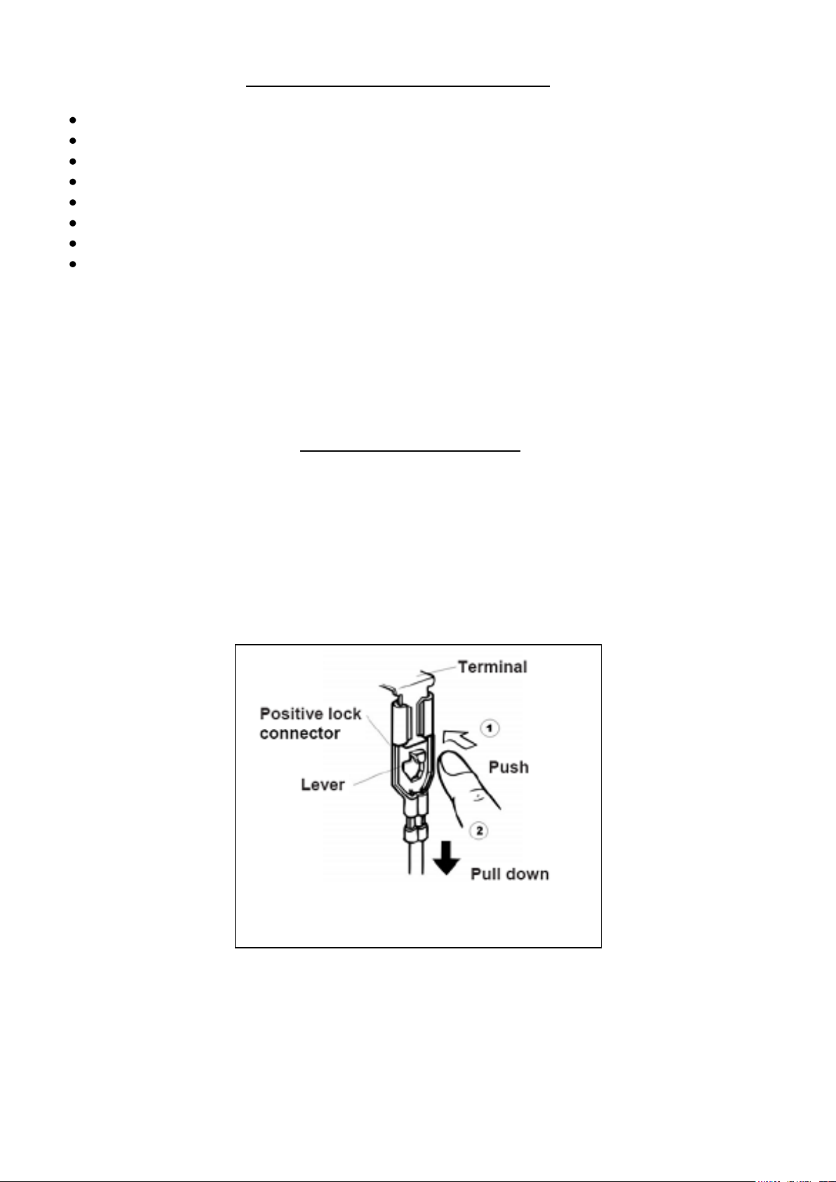
Positive Lock Terminal arrangement.
Safe Electrical Working Practices
Remove Power cord, Fuse or Switch off the circuit breaker.
Always check appliance with multimeter to ensure the supply power is disconnected.
Use only insulated tools & equipment.
Wear insulated shoes.
No water on the floor or working space.
Reduce the amount of exposed skin, by covering your arms and legs.
Remove jewellery (Rings, Watches etc).
It is essential that you conform to all “Working Live” and “Risk Management” statutory
requirements.
Positive Lock Terminals
The indoor & outdoor PCB’s are fitted with “Positive Lock Terminals”.
To remove Positive Lock Terminals: Push the lever forward & lightly pull down on the terminal.
Note: When reconnecting the Positive Lock Terminal, connect it so that the lever faces towards the front
of the unit.
Page 4 KSSSI113
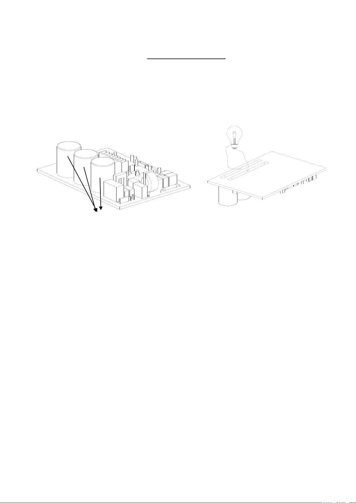
Capacitor Discharge
Discharge the capacitors located on the outdoor main PCB assembly.
Note: Even if the power supply has been disconnected, high voltage power can be stored in these
capacitors.
Discharge the capacitors with the use of a 25 or 40-Watt incandescent globe. As illustrated below.
Electrolytic Capacitors Bulb (25-40W)
Page 5 KSSSI113
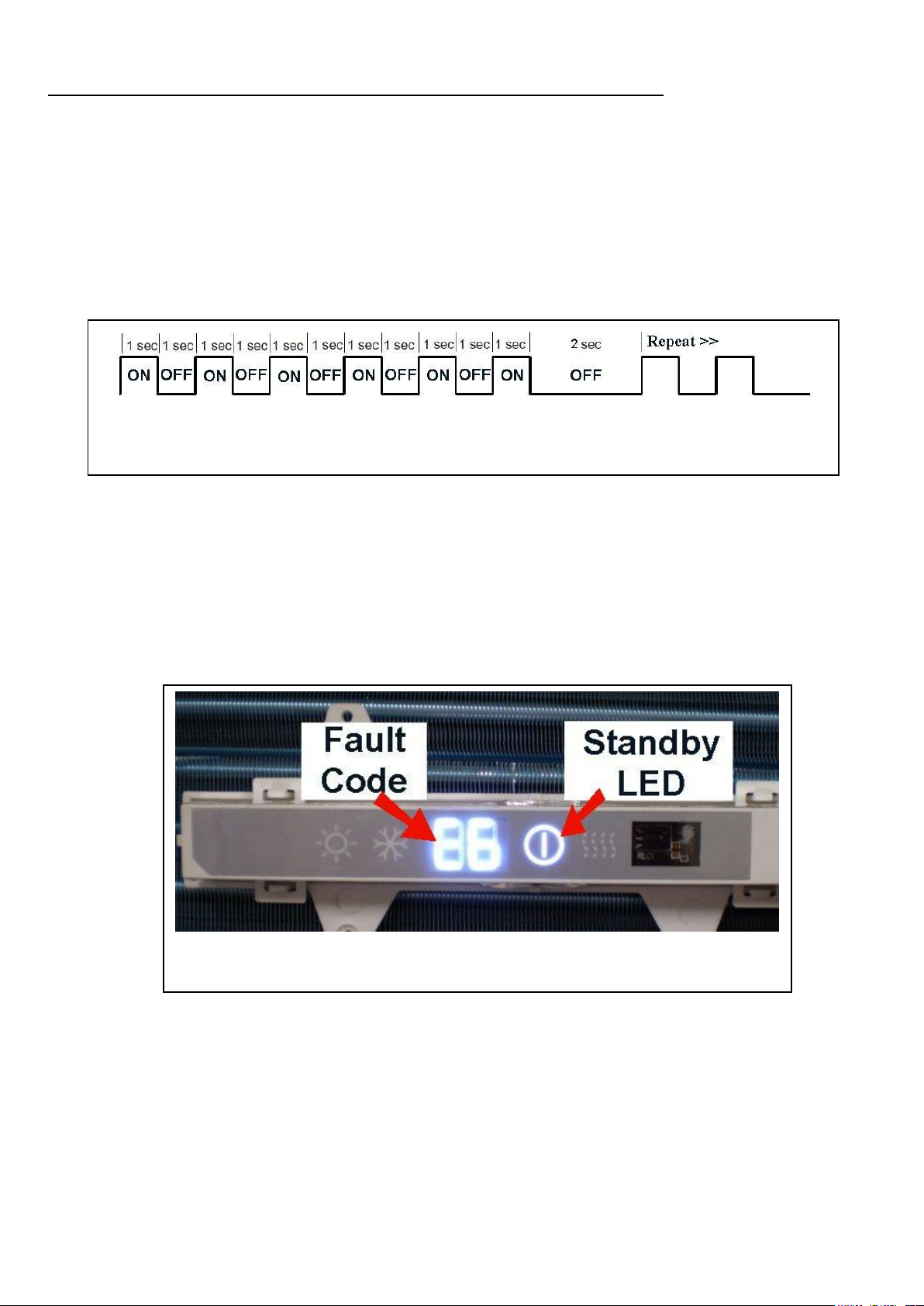
Fault Code (E6-Communication) & Standby LED indicating fault type.
(Communication Fault – Standby LED)
LED Flash Code Sequence Description (Indoor Display PCB)
# In the event of a complete shutdown or an operational control adjustment the Standby, Heating or
Cooling LED’s on the indoor display PCB flash to indicate this sequence.
Note: The LED’s flash at a 1 second rate for the required number of flashes, and then a 2 second pause
before repeating the 1 second rate sequence.
# Example of LED sequence:
# Example of fault code & LED sequence:
Page 6 KSSSI113
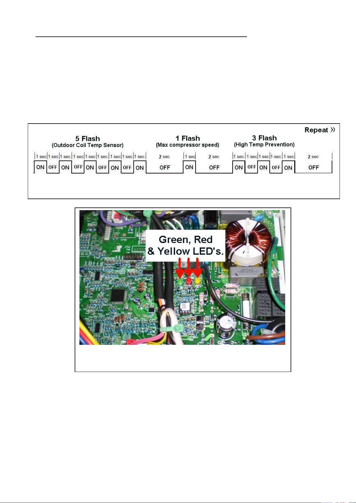
LED locations on outdoor PCB
Mutable fault code sequence.
LED Flash Code Sequence Description (Outdoor PCB)
# In the event of a complete shutdown or an operational control adjustment the outdoor PCB Green,
Yellow & Red LED’s flash to indicate this sequence.
Note: The LED’s flash at a 1 second rate for the required number of flashes, then a 2 second pause
before repeating the 1 second rate sequence.
Note: Two or more faults can appear in the one LED fault sequence.
# Example of LED sequence:
Green LED: Outdoor unit, flashing at 1 hertz.
# Normal communication.
Red LED: Outdoor unit, flashing at 8 times.
# Normal operation.
Yellow LED: Outdoor unit, flashing once every two seconds.
# Normal operation.
Page 7 KSSSI113
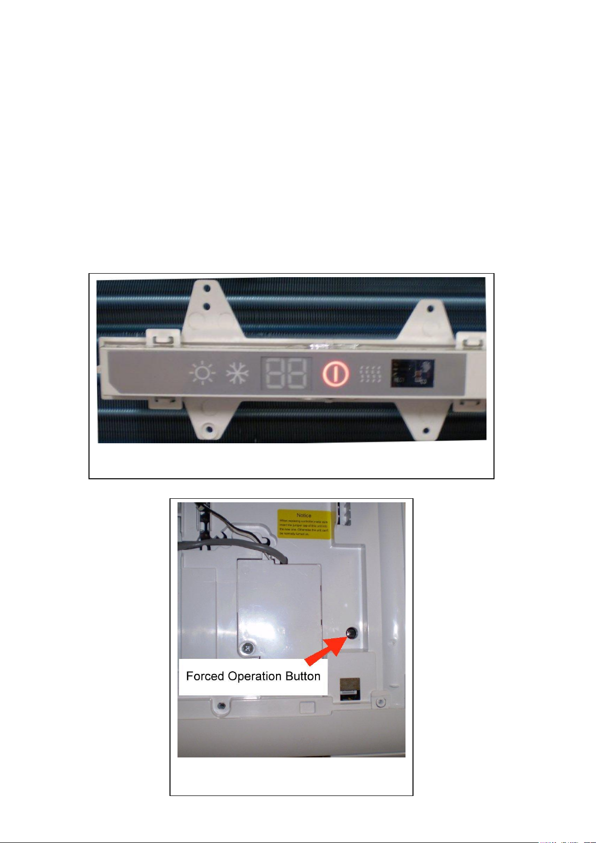
Standby indicator on Display PCB assembly.
Button located under indoor filter cover.
Not Operating:
# Check the wiring configuration from the outdoor unit to the indoor unit. Is it wired up correctly
in accordance to the wiring diagrams provided on both indoor & outdoor units? (Refer pages 29
to 31)
# While the unit is in “standby” mode, check if the red stand by light is on?
# Try operating the unit by the forced operations button: By pressing the button once, the unit
should activate in Auto mode. Pressing it twice will turn the unit off.
# If the unit can be operated by the forced operations button & the red stand by light was on,
check the remote controller.
# If the unit can be operated by the forced operations button & the red stand by light was off,
replace the display PCB assembly.
# If the unit cannot be operated by the use of the remote control or the forced operation button,
check for supply voltage at the following points, illustrated on the next page.
Page 8 KSSSI113
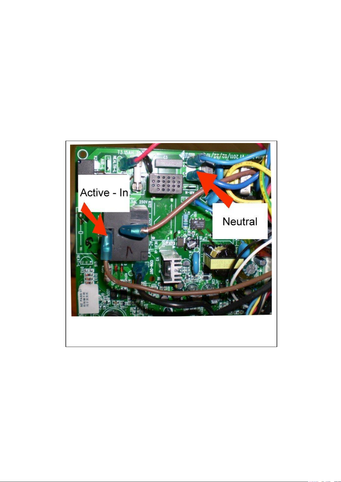
Active & Neutral Supply voltage points from service cord to indoor
PCB.
Not Operating Continues:
# Check for supply voltage at the following connection points:
From the isolation switch to the Active-In & Neutral connector points located on the indoor
PCB.
If supply power is available at the above connector points, yet the unit can still not be operated
by the remote control or the forced operation button, replace the indoor PCB.
Page 9 KSSSI113

Diagnostic Display Mode Description:
Built into the software for models: KSV26HRC & KSV35HRC are two different diagnostic methods:
(Fault Codes & Condition Codes) that can be used to help diagnose various faults.
These two diagnostic types are described in the following pages.
Note: Where there is referral to (Delayed)
# This indicates a time delay before the fault code in question is displayed.
Note: Where there is a referral to (Remote Control Access – 3)
# This indicates the need to use the remote controller to view the relevant fault code.
This is achieved by pressing the “Light” button 3 times within three seconds.
Note: Where there is a referral to (Remote Control Access – 5)
# This indicates the need to use the remote controller to initiate a selected “Test State”.
This is achieved by pressing the “Light” button 5 times within three seconds.
Note: Where there is a referral to (DRED)
# This indicates the unit in question is fitted with a “Demand Response Electrical Device” that enables
the compressor to operate at various capacities (75% of total capacity, 50% of total capacity &
compressor off).
Fault Code Descriptions:
Red LED: Outdoor unit, flashing at 1 hertz.
(Frequency Limit)
# This indicates the compressor has reached its maximum setting speed.
E4, Indoor Unit.
Indoor Standby LED, flash 4 times.
(Compressor Discharge High Temperature Protection)
# Check the outdoor coil for airflow obstructions.
# Check the outdoor fan motor for correct operation.
E5, Indoor Unit.
Indoor Standby LED, flash 5 times.
(AC Over-Current Protection)
# While the unit is in operation, check the maximum current draw. If it’s above the maximum current
rating illustrated on the outdoor rating plate, check operation of the compressor.
Page 10 KSSSI113
 Loading...