

Page 1
Thermetic
TILTING PRESSURE BRAISING PANS, ELECTRIC
(GX........)
US INSTALLATION INSTRUCTIONS
Doc. 62.9719
Edition 1
03.2005
Page 2

CONTENTS
1. GENERAL REMARKS ........................................................................................................ 3
2. PACKAGING / TRANSPORT ............................................................................................. 3
3. TECHNICAL DATA / DIMENSIONED DRAWINGS / INSTALLATION PLANS ................. 4
3.1 TILTING BRAISING PANS (GX........)................................................................................................4
4. FLOOR GULLIES ................................................................................................................5
5. MOUNTING / POSITIONING / FASTENING IN PLACE / ALIGNMENT ............................. 5
5.1 Positioning ........................................................................................................................................5
5.2 ADJUSTMENT FOR BOILING AND FRYING PANS ........................................................................6
5.3 ACCESS TO INSIDE THE CONSOLES AND SUPPORT .................................................................6
5.4 COVERS (PANELS) ..........................................................................................................................6
6. INSTALLATION .................................................................................................................. 7
6.1 ELECTRICAL CONNECTION ........................................................................................................... 7
6.2 UNIVERSAL CONTROL PARAMETER SETTINGS .........................................................................8
6.3 THERMACAM / HACCP (optional) ................................................................................................ 10
6.4 INSPECTION PROCEDURES / TEST OF FUNCTIONS .................................................................11
7. DECOMMISSIONING / DISMANTLING / DISPOSAL ...................................................... 11
Page 3
1. GENERAL REMARKS
Responsibility
The setting up, adjustment and initial commissioning of appliances must be carried out in accordance with the manufacturer's instructions and may only be done by authorised
personnel. The installations for the electricity, steam, condensate, hot water, gas and water supplies as well as ventilation
must be laid or fitted by approved installation contractors in
accordance with specific national and local regulations. The
installation contractors are responsible for the correct layouts
and installations in conformity with all safety regulations. The
warning signs and specification plates fitted to the appliances
must be strictly adhered to.
Validity
These instructions for installation refer to the THERMETIC tilting appliance program with appliances of different sizes: tilting
boiling pans, tilting braising pans and tilting pressure braising
pans.
Dimensioned drawings and installation plans of this document
are only for information purpose to the installers. These plans
may not be used for planning or projecting kitchens.
Tests/certificates
All electric appliances are tested by testing institutes. They fulfil standards UL 197 as well as NSF4 1999 and NSF 12 1992
(Chilltherm). The appliances are marked with the UL marking
on the specification plate.
2. PACKAGING / TRANSPORT
Types of packaging
Various types of packaging are used dependent on country of
destination. All versions of these appliances are transported
on a wooden frame or floor, are affixed to these with plastic
straps and located with wooden strips to prevent slipping.
Destination Overseas:
Version: Heavy, crate closed
Floor: Wooden floor
Floor fixing:
Side and cover frame:
Water and dust protection: Plastic film
Physical outer protection: Closed crate
Held together by: External steel banding
Transport: Forwarder
Stack ability: max. 4 appliances
Packaging markings
The external surfaces of the packaging have the following
markings which must be strictly adhered to:
• Forwarding label with the following information:
- Delivery company
- Delivery company's order number
- Customer's order number if available
- Delivery address
- Package number
- Net weight in kg
- Gross weight in kg
- External dimensions of the packaging
• Handling stickers with pictograms
- Umbrella = Keep dry; the packaged appliance
may not be stored outdoors
- Glass = Contents fragile
- Arrow pointing up = Only transport and store the
appliance in this position
- Stacking number = Number of appliances that can be
stacked (1 = cannot be stacked)
- Ice crystal and roof = Protect against frost
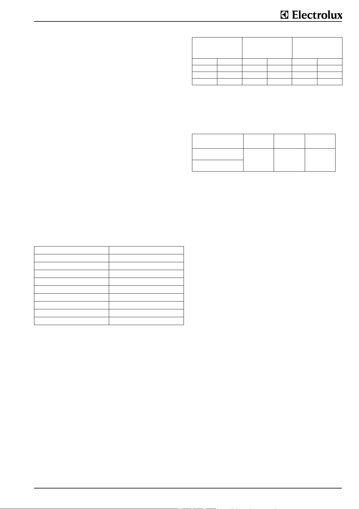
Transport weights
The precise gross and net weight is given on the forwarding
label. Due to the wide range of appliances, only the maximum
weights possible for the "European light" version are summarized below:
Tilting pressure
braising pans
max. gross weight max. net weight
GX........ kg lb. kg lb.
060 LT (15.9 gal) 250 551 230 507
090 LT (23.8 gal) 320 705 300 661
100 LT (26.4 gal) 340 750 320 705
150 LT ( 39.4gal) 360 794 340 750
Packaging dimensions
The precise external dimensions of the packaging are given on
the forwarding label attached to the outside of the packaging.
The maximum dimensions of the "European light" style of
packaging are given below:
Appliance size
LT
Tilting pressure braising pans
60, 90
Tilting pressure braising pans
100, 150
Width Depth Height
mm inch mm inch mm inch
1400 55.1 1200 47.2 1100 43.3
1800 63.0 1200 47.2 1100 43.3
Handling
Both packaged as well as unpacked appliances are best lifted
and transported whenever required with a pallet truck which is
inserted into the wooden frame or under the wooden base.
This applies to both the loading and unloading of trucks as well
as to handling operations on the installation site.
For handling by a crane, the unpacked appliances do not have
any specific lifting points to which they can be attached. It is
necessary to wrap two straps or ropes around the appliance
when lifting is required. Wrapping straps or ropes around the
appliance may only be done at the sides and not round the
front and the rear. The straps or ropes should be arranged
approximately 150 mm (5.9“) from the outer edges.
62.9719 Page 3
Page 4
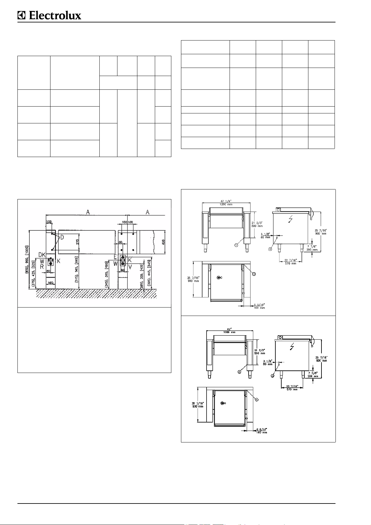
3. TECHNICAL DATA / DIMENSIONED DRAWINGS / INSTALLATION PLANS
Electr.
Power
kW lt
12.2
18.2
Boiler
size
(gal)
60
(15.9)
90
(23.8)
100
(26.4)
150
(39.6)
PNC
Appliances
Appliance type Width
Depth
Height
Feet,
Wheel
Height
inch
(mm)
9CHG583299
9CHG583300
9CHG583301
9CHG583302
9CHG583303
9CHG583304
9CHG583305
9CHG583306
9CHG583307
9CHG583308
9CHG583309
9CHG583310
GXWBOEOOOO
GXXBOEOOOO
GXYBOEOOOO
GXWDOEOOOO
GXXDOEOOOO
GXYDOEOOOO
GXWEOEOOOO
GXXEOEOOOO
GXYEOEOOOO
GXWHOEOOOO
GXXHOEOOOO
GXYHOEOOOO
47.2
35.4
27.6
(1200
900
700)
63
35.4
27.6
(1600
900
700)
7.9
(200)
These illustrations are not intended for the planning and laying
of the supply lines in the building.
Installation plans for tilting boiling pans (.U........), tilting
frying pans (.P........), tilting pressure braising pans
(GX........)
Tilting Braising Pans
Type 060 LT,
electric
Dimension A (mm) 1200 1200 1600 1600
(inch) 47.2 47.2 63 63
Braising surface (mm)
(inch)
Pan depth in (mm)
T(inch)
Net content (litres)
(gal)
max. capacity
El. heating power in kW 12.2 12.2 18.2 18.2
Voltage 208V/3~N
Current A
Voltage 240V/3~N
Current A
Voltage 480V/3~N
Current A
620 x 490
24.4 x 19.3
220
8.7
67
17.7
35.5 35.5 43.8 43.8
31 31 38.1 38.1
15.7 15.7 23 23
090 LT,
electric
620 x 490
24.4 x 19.3
290
11.4
94
24.8
100 LT,
electric
990 x 490
220
8.7
104
27.5
990 x 490
39 0 x 19.3
290
11.4
145
38.3
Dimensioned drawings
H Height for all types 900 mm (35.4“)
S Height of feet / wheel 200 mm (7.9“)
150 LT,
electric
R Condensate drain or hot
A Width of appliance (see
dimensioned drawing)
E Electrical cable protruding
from wall
V Steam or hot water supply,
Sandvik coupling, nominal
width 25 mm
water return,
Y Sandvik-coupling, nominal width 25 mm
W Hot water connection G
1/2", NW15
K Cold water connection G
1/2", NW15
DKWater drain for steam con-
densation (.X........)
Fig. 1 Installation plans for tilting boiling pans, tilting
frying pans, tilting braising pans
3.1 TILTING BRAISING PANS (GX........)
Model (optional) Pan bottom made of steel or chrome-nickel
plated steel
Style of mountingFloor mounting with floor support with con-
sole.
Tilting Motor tilting with lifting motor
Control system PROCESS COMFORT control system with
pan-base and cooking temperature control
and programmable cooking and starting
time.
Fig. 2 Dimensioned drawings
Tilting frying pans
Page 4 62.9719
Page 5

4. FLOOR GULLIES
In the case of tilting appliances, floor gullies with loose gratings
and floor drains which serve as drains when cleaning are provided for near to the outlet. Floor gullies can be designed for a
single appliance or for a whole group of appliances. There is a
very wide variety of types and sizes. Please consult the relevant installation plans for information concerning layout and
type.
In general, the floor gullies with their drains are concreted into
the floor by the builder.
A Pan sizes 80 to
150 litres; Grating 500 x 1000
mm (19.7x39.4“)
B Pan sizes 200 to
400 litres; Grating 600 x 1200
mm (23.6x47.2“)
Fig. 3 Sample dimensions of individual floor gullies for
tilting boiling pans without drain valves.
titions, kitchen equipment, decorative cladding, etc., it is recommended that the latter are made of incombustible material
or that they are clad in a suitable, incombustible material or
tiled. The regulations governing fire protection must be
adhered to as closely as possible.
Preparation for fastening in place
Before the appliance is brought to the correct place and put in
position, the following connection points must be prepared
dependent on the type of appliance:
• Fastening elements, i.e. drilling holes and inserting plugs.
Explanations for this are included in the relevant sections
under "Fastening".
• Remove the Sandvik connectors, nominal width 25 (1“),
from the hoses and weld them onto the supply lines provided on-site (see § 6.2.).
• Prepare the water connections and, possibly, fit a shut-off
valve.
Setting up
The appliance should be transported to the place where it is to
be set up in accordance with § 2.
Removal of the packaging:
The packaging, a wooden crate, should not be removed until
immediately before the appliance is to be set up in place. All
side and top packaging parts as well as the fastening elements
must be removed in sequence. The appliance should remain
on its wooden transport frame or base until at the site for
installation.
Fig. 4 Typical, floor gully for a single appliance with a siphon
(S) made of stainless steel (728 342 984)
5. MOUNTING / POSITIONING / FASTENING IN PLACE / ALIGNMENT
In principle, the appliance must be installed in its scheduled
location in accordance with the valid plans. The appliance is
scheduled for connection to fixed power- and water supplies.
The installation dimensions are given on the plans.
The appliances are suitable for setting up as single appliances
or as a group of appliances. They can be set up freely in the
room, side by side, at the side and/or at the back against a
wall.
5.1 Positioning
Transport the appliance on its
wooden frame to a point directly in
front of where it is to be set up. The
installation connections protruding
from the floor should be at the side
as close as possible to the wooden
frame.Slide the appliance off the
wooden frame so that all the installation connections are within the
appliance.
Tip until the appliance touches the
floor. Raise the front and pull out
the wooden frame.
Lower the appliance carefully and
slide it into the correct final position.
wall, which is installed at the equipment back of the appliance.
Appliance on feet.
Distances/walls
Valid only for braising pans and pressure braising pans.
These may not be positioned against combustible walls. If an
Fig. 5 Appliance foot
appliance is set up next to or against temperature-sensitive
furniture or similar, a safety gap of approximately 50 mm (2“)
should be maintained or some form of heat insulation fitted.
When setting up an appliance in the close vicinity of walls, par-
62.9719 Page 5
Page 6

D Turn the lower part of the feed (FU / Fig. 5) to adjust the
appliance high.
The feed are adjustable from 100 to 200 mm. A high of 200
mm can be recommended and results in an appliance high of
900 mm.
Note:
Adjustment of the legs shall provide an unobstructed
clearance of minimal 150 mm and maximal 200 mm
beneath the unit due to sanitary and stability aspects.
The lower part of the foot must not be unscrewed too far.
The exposure of threads is prihibited.
5.2 ADJUSTMENT FOR BOILING AND FRYING PANS
Height adjustment
Setting the height correctly is done with the feets (see 5.1).
The correct position is found by placing a spirit level on the
edge of the boiling pan or the bottom of the frying pan.
Horizontal position
The two end positions "tilted" and "horizontal" are determined
by the end settings of the motor. The "horizontal" end position
of the pans can be adjusted by resetting the rear attachment
point of the motor. The motor is attached by 2 screws with
nuts. To adjust the end position, release the nuts and add or
remove pieces. Adding additional pieces will increase the tilting angle to the back while removing packing pieces will
increase the tilting angle to the front. Adjustment is correct
when the pan is exactly horizontal when the motor spindle is
fully extended. After setting, the screws with the washers must
be retightened firmly.
5.3 ACCESS TO INSIDE THE CONSOLES AND SUPPORT
Switch panel (F) removal:
Floor mounting on plinth
Unscrew the two screws at
location (1) underneath the
switch panel and the nuts (MH)
at location (2) on the top, pull
out the switch panel at the bottom and then lift up out of the
fixation. The panel is turned up
90° like a door and hung at the
top on the console.
Cover (A) removal:
If there is a connecting rail
installed to the cover it has to
be removed first. (see 5.3.1.).
Remove the nuts (MU) (two on
a single console, four on a twin
console) at the relevant location (2). Lift the cover at the
front and pull it out of its clip
attachment at the back (3). If a
mixing unit is fitted, this does
not need to be removed from
the cover.
Service panel (V) removal:
Remove the two external nuts
(6) at the front and pull the
panel from its rear attachment
points (5).
Side wall (S) removal:
To remove this, the switch
panel (F) must be removed
Hanging the operating panel
(F) on the console
first. Remove the nuts (4) and
(5) inside. The upper internal
wall (W) cannot be disassembled. It must be removed and
refitted together with the pan.
The panels are refitted in the
reverse order to that described
above.
Cover (A). The height of the
cover can be levelled by fitting
more or fewer shims (BE) and
tightening the nuts (MH).
Adjusting the axle height
The height of the appliance tilting axle (4) can be adjusted as
follows:
• Release the 4 bearing screws (1).
• Release the locknut (2).
• Dependent on requirement, screw in or out the screw (3)
until the correct height is set.
• Tighten the locknut (2).
• Tighten the 4 screws (1)..
5.4 COVERS (PANELS)
The panels are fixed to the appliance casings during setting up
with special M5 screws.
Page 6 62.9719
Page 7

6. INSTALLATION
Please refer to §1. for implementation and responsibility.
6.1 ELECTRICAL CONNECTION
Check and ensure that the mains voltage matches the voltage
given on the specification plate. The specification plate is
located on the left-hand side of the right-hand console.
Important
• The electrical connections must satisfy local house installation regulations.
• The valid, national, local regulations of the electricity-supply inspection authorities responsible must be observed.
• The corresponding arrangements must be made on-site for
the earthing connection and fuse protection for the appliances. The appliance must be earthed.
• At the place marked with a , the appliance must be
connected to a potential equalization system with a mini-
mum conductor cross-section of 10 mm² (0.016 inch²). The
correspondingly marked connection terminal must be used
for this purpose. When set up in block configuration, all
appliances must be interconnected as potential equalisation.
• The appliance is designed for connection to a fixed power
supply. If the appliance is installed against a wall, the supply must pass through the prescribed place of the rear
panel or through a prescribed place of the inner side panel.
• After the appliance has been assembled, the shock protection of all live parts and insulated parts must be checked.
• An isolating device working on all poles and with a minimum contact opening of 3 mm (0.12“) must be provided on
site.
• When faulty-current circuit breakers are used, ones for a
rated breaking current of 30 mA or more should be used.
• When using faulty-current circuit breakers (both existing
faulty-current circuit breakers in the installation as well as
for new installations), only one pulse-current sensitive
faulty-current circuit breaker may be connected in series on
these appliances.
• All field wiring conductors shall be suitable rated for the
maximal voltage involved (300V / 600 V).
Connection
Each appliance is accompanied by a complete connection and
wiring schematic. This contains full details of the technical
specifications (electrical rating, voltage, amperage, etc.). The
power connection is via an on-site electric cable, an appropriate length of which protrudes from the floor or the wall.
The terminal box is located under the cover (A) in the right
console. The right-hand cover is marked with a symbol.
The cover must be removed to connect the appliance to the
electricity supply. This is done as described in §5.1.2. and
§5.2.2. respectively. The power cable comes out of the floor or
the wall inside the appliance. The power connection must be
made in accordance with the connection diagram. The cover
must be correctly refitted after the power connection has been
made.
Additional terminals for power optimizing systems (EO/SI) or
potential-free contacts (PK) for the external monitoring of the
appliance are available as options. These connections are
made according to the electrical schematic
Mains connection for
electrically heated appliances
A = Mains connection
G = Appliance outputs
Fig.6 Mains connection 200-440V/3~N
Mains connection for
appliances without stirring
systems with steam or hot
water
A = Mains connection
G = Appliance outputs
Fig.7 Mains connection 200-250V/1~N
The connection bolts on the frame are marked as follows:
Earth conductor Potential equalization
POWER OPTIMIZATION SYSTEMS (EO)
Appliances in major kitchens are frequently attached to electrical power monitoring systems. The purpose of these systems
is to avoid the occurrence of current load peaks when the
appliances are simultaneously under full load. In this way, both
investment costs in the electricity network as well as, to a
greater degree, connection charges for electricity can be
saved. The following methods are used to achieve this:
• The appliances are connected to a power grid maximum
current monitor which arranges for individual appliances to
switch off in accordance with the power ceiling set.
• Power limiting systems are a more sophisticated method.
Current peaks are eliminated without any noticeable influence on cooking processes. On the basis of a continuous
comparison of the actual current consumption of the entire
establishment with a predetermined maximum current limit,
appliances are switched on and off for very short times in
accordance with the program data specific to the appliances.
Wiring
Power monitoring devices require the following information
from all appliances:
• Position of the ON-OFF switch
• Operating status of thermostats, electronic controllers, etc.
If an appliance has several controllers, each circuit is allocated its own control circuit.
This information is passed on to the monitoring device via 4
different lines.
Line A signalizes the switching status (heating on or off) of
the appliance (24÷230V) and is connected to the
secondary side of the power switch.
Line B signalizes the operating status (heating on or off) of
the appliance and is connected to the thermostat or
controller pcb respectively. Lines A and B may not be
of different voltages.
62.9719 Page 7
Page 8

Line C releases the appliance. When the power monitoring
device releases the appliance, lines B and C are
linked to each other by an outside contact.
Line D forms the reference potential for the lines interrogated
The power contactors are located in the appliance or in an
external cabinet. The internal wiring for a power monitoring
device can be fitted as an option on all appliances.
Important
If an appliance was ordered and delivered with the option EO,
then it is only working correct if EO is connected on site.
In case the appliance will be connected to the EO installation
not immediatly after installation or later, the terminals B and C
of the appliance (see electric diagram) must be bridged for correct operating. When the EO installation will be connected later
the bridge must be removed.
Further the parameter 4 of the electronic control must be
checked or corrected if necessary.
POTENTIAL-FREE CONTACT (PK)
The potential-free contact on an appliance is independent of
the power optimization system (EO). It is required to display on
an external switchboard whether the appliance is switched on.
The terminals are marked 21 to 29.
CONNECTION TO A POTENTIAL EQUALISATION SYSTEM
The appliance is to be connected to a potential equalization
system with a minimum conductor cross-section of 10 mm²
(0.016 inch²). The connection terminal marked must be
used for this purpose (EN 60 335 1 + 2). The connection con-
sists of a bolt threaded M6 and is located on the frame of the
appliance.
Connection according to diagram.
When set up in block configuration, all appliances must be
interconnected as potential equalization.
.
1 Cable lug Ø 6 mm (0.24“)
2Nut M 6
3 Spring washer M 6
4 Washer M 6
6.2 UNIVERSAL CONTROL PARAMETER SETTINGS
New appliance installation
In the case of new appliances, the control system is programmed at the factory to the appliance-specific setting.
When the appliance is installed at its intended site, the fitter in
charge of installation must set or check the following parameters on the control system. The parameter values are different
for each software version.
Appliance-specific parameters are only set on the basis of the
type of appliance. User-specific parameters are dependent on
user order, user requirements, siting terms and are only appliance-dependent to a certain degree.
The parameters are programmed at the factory to the default
setting (GS) if no specific information is given.
For selecting the parameter number (PNr.) and changing the
parameter value (X) the buttons Q to P on the membrane keyboard are used. The buttons are located in the bottom row on
the operating panel. Buttons V and P are located under the
membrane and are sometimes not visibly marked.
TT Button, activation of settings
LT Lamp, cooking temperature
DT Button, cooking time
LD Lamp, cooking time expires
ZT Button, starting time
LZ Lamp, starting time
LR Lamp, soft settings
Q Button, acoustic signal
R Button, soft
LS Lamp, temperature
pre-setting
AT Display, cooking tempera-
ture
T Temperature selection knob
AD Display, remaining cooking
time
D Cooking time knob
AZ Display, time
Z Starting time knob
P
V
S Control switch
Fig. 9 Right console
Fig.8 Connection to the potential equalization system
Parameter numbers (PNr.)
Starting position: supply switched off (switch S at 0)
1st
combination
Press and hold
buttons
2nd
Press button
* *
Supply to be switched on (turn switch S to I) Press buttons continu-
Waiting time between
the different combinations is 3 seconds
maximum
ously until the 2nd
beep, then press 2nd
combination (for the
first time only 1 beep)
Hold button R pressed
until the 2nd beep,
then release.
*
Display (AT): Parameter PNo. . . 1 appears
Display (AZ): None
Page 8 62.9719
Page 9

The parameter numbers (PNo.) and the values (X) which devi-
Ð
ate from the standard setting can now be entered alternately
on the display (AT).
As the same display is used to show the numbers (PNo.) and
the content (X) of the parameters, the following difference is
made between the two figures:
Kind of display (AT): Meaning of display:
with 3 decimal points (e.g.
1.0.3.)
without decimal points (e.g.
126)
Number of parameter PNo
Content (X) of parameter (e.g.
temperature)
Changing the parameter number (PNo.) and content (X))
Starting position: supply switched off (switch S at 0)
1st
Press button
2nd
Press button
3rd
Press button
*
*
*
Changing
(AT) from:
parameter number
(PNo.) to
parameter content (X)
or vice versa
Increasing the display
entered under 1.
parameter number
(PNo.)
Ï
or parameter content
(X)
Reducing the display
(AT):
parameter number
(PNo.)
or parameter content
(X)
the display
SETTINGS
SOFTWARE VERSION BPTH 5.06c
Tilting pressure braising pans, electric
PNr.
Parameter
number
4 0 Power optimization system EO without:0
6 1 Heating with tilting
9 0 Pressure switch in the food compartment 1
12 0 Automatic steam condensation without:0
19 1 Power settings and boiling temperature 0
29 1 Deaeration sensor of the jacket 0
31 0 HOLD function
32 0 HACCP function without:0
35 0 Function of the steam condensation sensor without:0
49 0 Appliance code 3
50 1 Appliance type 2
54 4 Quantity of switching steps 2
78 30 Duration of periods of the power levels
79 25 Power level L1
83 50 Input of height above sea level of the installation
138 33 Running time of the 3-step motor valve
159 0 Difference between boiling temperature and set-
GS
Default
setting
site in 10 m (500 m above sea level = 50).
(running time + 10% in seconds) p.ex.:
Running time 29 sec.
Running time 40 sec.
ting during the function power setting and HOLD
Designation
with:1
with:1
with:1
with:1
X
Rate of change of the displays
Increases (button P) or reductions (button Q) can be done at
three different speeds:
• Press the button brieflychanges in single steps
• Press the button longer
• at least 1 second the display changes slowly
• press for at least 5 seconds the display changes fast
End of parameter programming
If the content (X) of a parameter (PNo.) is changed, the
changed value is stored when the display (AT) is changed
from parameter content to parameter number using the button
R. The following applies for the last parameter content
changed or if only a parameter content has been changed.
Parameter programming can be finished in 2 ways dependent
on whether the changed value is to be stored or not.:
Finishing: Procedure:
Changed value to be
stored
Changed value not to be
stored
Display (AT) shows the parameter number
Switch off control switch (S)
Display (AT) shows the parameter value (X)
Switch off control switch (S)
62.9719 Page 9
Page 10

Default setting (GS) of the parameters
In the case of new appliances, the control system is programmed at the factory to the appliance-specific setting. In the
case during installation of the appliance the programming of
the default settings will be necessary, precede as described
below.
The default setting of the parameters is the same for all appliances which are equipped with this control system. Dependent
on the type of appliance, more or fewer parameters are
required with values that differ from each other to some
degree. 3 of the 4 buttons on the membrane keyboard (Q, R, V
and P) are used for the programming of parameters. The 3
buttons are located in the bottom row on the operating panel.
Buttons V and P are located under the membrane and are
sometimes not visibly marked)
Starting position: supply switched off (switch S at 0)
1st
combination
Press and hold
buttons
2nd
combination
Press buttons
3rd
combination
Press buttons
* *
Supply to be switched on (turn switch S to I) Press buttons continu-
* *
Waiting time between
the different combinations is 3 seconds
maximum
ously until the 2nd
beep, then press the
2nd combination
Press buttons continuously until the 2nd
beep, then press the
3rd combination
Press buttons continuously until the 2nd
beep
* *
4th
hold
button R
⇓
⇓
*
(*) Display (AT): After "def" is displayed for approx. 2 seconds,
the actual value of the current food temperature will appear.
Display (AZ): Clock time appears (only with process com-
fort control).
The control system program now contains all the default settings for the software version of the microprocessor installed.
Important
If the default setting (GS) of the parameters of an appliance
which was already in operation is programmed for new, all
parameters which registers running times are set to zero.
6.3 THERMACAM / HACCP (optional)
Programming in the address of an appliance
Appliances can be optionally equipped with the program-linked
cooking process procedure. Cooking processes can be programmed, analysed, logged and documented and are thus
part of the HACCP system (HACCP = hazard analysis and critical control points).
The standard operating instructions or a special set of HACCP
operating instructions contain information on the use of and
the programming, analyzing, reporting and documenting of
cooking processes with the help of an external computer.
After the appliance has been installed and commissioned, it
must be assigned - i.e. programmed with - a specific address
(number). The instructions below describe how to do this.
System requirements
• Software version: BPTH5.03 or higher.
Hold button R pressed
until the 2nd beep,
then release.
(*)
• Parameter no. 32 of the appliance control system must be
set at "1". Please refer to chapter 6.2. for information on
how to request and set parameters.
• Only use the "S" switch to switch on the appliance. No
cooking processes may currently be in operation.
ZT Button, starting time
LZ Lamp, starting time
LR Lamp, soft settings
Q Button, acoustic signal
R Button, soft
LS Lamp, temperature
pre-setting
AZ Display, time
Z Starting time knob
P
V
S Control switch
Fig. 10 Right console
Starting position: supply switched off (switch S at 0)
Press keys (1st
sound), hold for
appr. 4 sec.
until the 2nd
sound; then
release keys.
Press the key
briefly and
release it.
* *
ISEL
will be displayed
display (AZ)
on the
(Interface Selection).
Baud
will be displayed
on the
display (AZ)
*
Press the key
briefly and
release it.
Press the key
briefly and
release it.
*
The value
9600
(Baud
rate) will be
(AZ)
value is displayed, it
must be changed to
9600.Use the "Q" key
to increase the value
or the "P" key to
decrease it.
Baud
on the
displayed
. If a different
will be displayed
display (AZ)
*
Press the key
briefly and
release it.
Addr
will be dis-
played on the
.
(AZ)
display
*
Press the key
briefly and
release it.
Press the key
briefly and
release it.
*
A number between 0
and 255 will be
played (AZ)
number must be set to
the specific appliance
address (number).Use
the "P" key to increase
the value or the "Q"
key to decrese it.
Addr
played on the
(AZ)
. This
will be dis-
.
dis-
display
*
Press keys (1st
sound), hold for
appr. 4 sec.
until the 2nd
sound; then
release keys.
* *
The address of the
appliance and the
baud rate are now
saved
.
Page 10 62.9719
Page 11

6.4 INSPECTION PROCEDURES / TEST OF FUNCTIONS
Programming of the UNIVERSAL control
Before placing in operation for the first time the control system
must be adjusted according the Service Manual chapter "Programming Specific Appliance and Data/New appliance installation".
Inspection procedures / Test of functions
When mounting and installation have been concluded, all protective films should be slowly removed from the appliance with
care. Any adhesive residues should be removed with solvent.
Appliances may not be used before the protective film has
been removed.
Ensure that all accessories that belong to the delivery are
present and have been fitted.
Ensure that all warning plates are fitted in or on the appliances.
After the appliance has been connected up, the installation fit-
ter or service agent must carry out a test of all functions in
which all the programs and operating states of all operating
elements as laid down in the operating instructions are
checked.
• Electrically heated appliances
• Check the temperature regulators for their switching func-
tion.
• Check temperatures.
• Check all switching and warning elements.
The appliances are largely constructed of 1.4301 stainless
steel as well as many other materials, such as aluminium, nonferrous metals, insulating materials, electrical and electronic
components and plastics.
Safety equipment
Appliance Safety device
Electrically heated pans
.P........, GX.......
Excess-temperature thermostat on
the pan base
Cover safety valve
Training the operator
The user must be familiarized with the use of the appliance by
the representative of the firm responsible for installing the
appliance. The operating instructions enclosed with the appliance must be given to the user with the recommendation to
read them carefully. The operator should be urged to conclude
a servicing agreement with the service firm responsible.
7. DECOMMISSIONING / DISMANTLING / DIS-
POSAL
Decommissioning
All supply networks and connections to external lines must be
disconnected. Installations for the supply of electricity, gas and
water must be removed and disposed of by qualified fitters as
laid down by specific national and local regulations. It is the
responsibility of the fitters to ensure that their work and measures are appropriate and satisfy all safety requirements.
Dismantling
Dismantling can be done by a special team or by a scrap metal
dealer. The fastening points of the appliances on the floor or
the wall are removed. Blocks of appliances are split up for
easy transport. In the case of wall mounted appliances, as well
as for their transport, a pallet truck is required. Please refer to
§ 2 for information on weights, handling and transport.
Disposal
Usable equipment still in good condition can be repaired by the
manufacturer and used as pre-owned appliances. This also
applies to the individual parts of appliances.
Unusable, heavily damaged or obsolete appliances as well as
connection material is disposed of as scrap material at a scrap
metal dealer's. The latter handles the separation of the different materials and delivers them to a recycling company.
62.9719 Page 11
 Loading...