

Electrolux GU1EOEOOOO Service Manual
Thermetic
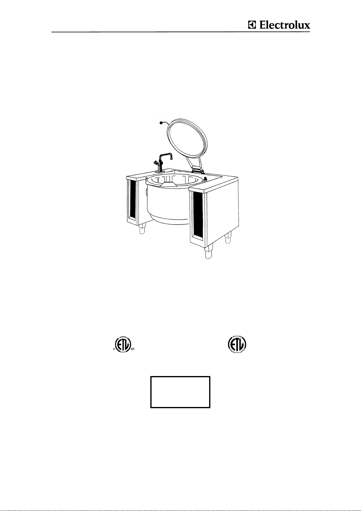
TILTING BOILING PANS, ROUND, GAS
(GU........)
(KU........)
US SERVICE MANUAL
Gas heated
TILTING BOILING PANS
Doc. 62.9693.03
Edition 1
09.2006

CONTENTS
1. CONSTRUCTION/ FUNCTIONS......................................................................................... 3
2. TECHNICAL DATA ............................................................................................................. 3
3. ELECTRIC DIAGRAMS ...................................................................................................... 4
4. MAINTENANCE CHECK LIST............................................................................................ 6
5. ACCESS TO INSIDE........................................................................................................... 7
6. FUNCTIONAL COMPONENTS.............. .... ... ... ... ... .... ... ... ... .... ............................................ 7
6.1 OPERATING FOIL ........................................................................... ..................................................7
6.2 UNIVERSAL CONTROL ............................................... .....................................................................8
6.2.1 PARAMETER PROGRAMMING .........................................................................................................................8
6.2.2 MANUAL PARAMETER INPUT ..........................................................................................................................8
6.2.3 PROGRAMMING SPECIFIC APPLIANCE AND USER DATA .......................................................................... 9
6.2.4 ADJUSTING OF TEMPERATURE MEASURING .............................................................................................11
6.2.5 TEST FUNCTIONS FOR SERVICE APPLICATION .........................................................................................11
6.2.6 TROUBLESHOOTING DISPLAY ......................................................................................................................12
6.2.7 OPERATING BOARD (UP) ...............................................................................................................................12
6.2.8 CONTROL BOARD (SP) ...................................................................................................... .............................13
6.2.9 CONTROL SWITCH (S) ........................................ ..................... ..................... ..................................................13
6.2.10 SAFETY THERMOSTAT (F1) ...........................................................................................................................13
6.2.11 FOOD SENSOR (B1) ........................................................................................................................................14
6.2.12 JACKET SENSOR (B2) ....................................................................................................................................14
6.2.13 DEAERATION SENSOR (B3) ...........................................................................................................................14
6.2.14 END SWITCH (ES) ............................................................................................................................................14
6.2.15 TERMINALS ......................................................................................................................................................15
6.2.16 CONTROL FUSE (X4) .......................................................................................................................................15
6.2.17 RELAY (K1) .......................................................................................................................................................15
6.2.18 HEATING RESISTOR (E11) .............................................................................................................................15
6.3 MOTOR TILTING ............................................................................................................................16
6.3.1 CONTROL SYSTEM (KS) .................................................................................................................................16
6.3.2 TILTING MOTOR (AN) ......................................................................................................................................16
6.3.3 SWITCH (CK) ....................................................................................................................................................16
6.4 BURNER SYSTEM ..........................................................................................................................17
6.4.1 FLAME ..............................................................................................................................................................17
6.4.2 AUTOMATIC GAS IGNITOR (A3) ....................................................................................................................17
62.9694.03 Page 1

6.4.3 BURNER ....................................................... ....................................................................................................18
6.4.4 SCREEN (BU) ............................................... ..................... ..................... ..........................................................18
6.4.5 GAS CONNECTION PRESSURE .....................................................................................................................18
6.4.6 THERMAL LOAD ..............................................................................................................................................19
6.4.7 DIFFUSOR (VU) and NOZZLE (DU) ................................................................................................................19
6.4.8 ELECTRODES (ED) (EM) .................................................................................................................................20
6.4.9 SEALANTS ................................................... ....................................................................................................20
6.4.10 CONVERSION TO ANOTHER TYPE OF GAS ................................................................................................20
6.4.11 GAS DATA TABLE ...........................................................................................................................................21
6.5 JACKET ..........................................................................................................................................22
6.5.1 SAFETY VALVE (SV) .......................................................................................................................................22
6.5.2 LEAKS / LACK OF WATER .............................................................................................................................23
6.5.3 DEAERATION SYSTEM ...................................................................................................................................24
6.5.4 DEAERATION VALVE (EV) .............................................................................................................................24
6.5.5 CHECK VALVE (RV) ........................................................................................................................................24
6.5.6 SIPHON (SP) ....................................................................................................................................................24
6.5.7 DATA PLATE, vessel (TY) ..............................................................................................................................25
6.5.8 INSULATION (see figure "Jacket") ................................................................................................................25
6.5.9 PAINT FINISH ...................................................................................................................................................25
6.5.10 JACKET PRESSURE TEST .............................................................................................................................25
6.6 ROTATION LINK (DK) ....................................................................................................................25
6.7 FAUCET ..........................................................................................................................................27
6.8 LID (D), ............................................................................................................................................28
6.8.1 LID HINGE (DG) ...............................................................................................................................................28
6.9 PAN .................................................................................................................................................29
6.9.1 BEARINGS, PIVOTS ........................................................................................................................................29
6.9.2 CASING (MN) ...................................................................................................................................................29
6.9.3 WASTE GAS FLUE (KI) ...................................................................................................................................29
6.10 APPENDIX
UNIVERSAL CONTROL DESCRIPTION OF PARAMETERS .....................................................30
Page 2 62.9694.03
VALIDITY
This document refers to the following tilting boiling pan program:
Gas heated tilting
boiling pan heated
.U.C......
080 E
.U.E......
100 E
.U.H......
150 E
.U.J......
200 E
.U.K......
300 E
ADDITIONAL DOCUMENTS
Operating instructions 76.9693.01delivered with the appliance
Installation instructions76.9699 delivered with the appliance
Spare parts list 76.9693.02distributed by the service
department
Electrical diagrams 91.4018, 91.4020
delivered with the appliance
SERIAL NUMBER YWWXXXXX
The serial number of the appliance is marked on the type
plate. The 8 digits give following information:
Y last digit of the year of production
WW week of production
XXXXX running number
SAFETY MEASURES
• Maintenance work, adjustments, conversions and repairs
may only be carried out by an authorized technician. These
technicians must be instructed by the manufacturer and
carry out the work in accordance with specific national and
local regulations. Parts requiring replacement are only to
be replaced by original spares.
• Strictly follow the attention and warning label indications on
the appliances.
• Servicing work on the gas supply may only be carried out
by gas company personnel or by an authorized installation
contractor.
• Cleaning and maintenance may only be carried out when
the appliance is cold.
• In case a connection with a seal is opened, always a new
seal should be used when installing the connection.
• The manager is responsible for ensuring that all compo-
nents relevant for safety (jacket safety valve, drain valve,
pressure gauge, thermostat, excess-temperature thermostat) are in perfect working order at all times. The operating
condition of these components must be examined by an
authorized technician at least once a year and any defects
remedied if required.
• Before beginning any servicing, all appliances must be dis-
connected from the power supply; the steam, condensate,
hot water and drinking water pipes must also be turned off
or closed. Disconnection from the power supply is effected
by switching off at the main switch or removing the fuses
fitted to the power supply.
• The internal wiring in the appliance as well as the earth
connections must be carried out in accordance with the
complete electrical schematic. Basically, all metal parts on
which electrical connections are located must be earthed.
• In case a connection with a sealing is o pened, always a
new sealing should be used when installing the connection.
• Boiling pans of this design and operating function do not
require special acceptance tests. They are subjected to a
pressure and operating test which meets the regulations on
the manufacturer's premises. Recurrent pressure testing is
not compulsory. To ensure the complete operating efficiency and safety of appliances, however, owners should
arrange for personnel authorized by the manufacturer to
check on all safety equipment and to conduct pressure
tests at regular intervals.
• All gas appliances are tested according to the standards
ANSI/NSF 4 - 2002 of Commercial Cooking, Rethermalization, and Powered Hot Food Holding and Transport Equipment and ANSI Z83.11-2002 and CSA 1.8-2002 of Gas
Food Service Equipment.
• After the appliance has been connected, the service age nt
must carry out a test of all functions in the course of which
all the programs and operating states of all operating ele-
ments as laid down in the operating instructions are
checked.
• The conclusion of a maintenance agreement should be
recommended to the user.
MAINTENANCE INTERVAL
An obligatory service check is required annually.
1. CONSTRUCTION/ FUNCTIONS
The food is uniformly heated by steam b y an external jacket.
The following sources of energy are used: electricity, saturated
steam and hot water. The pans are equipped with an electronic comfort control unit with regulation of the food temperature, with programming of the cooking time and with optional
programming of the starting time. The control system is operated via a membrane keyboard. The boiling pan has a variable-speed tilting facility powered by an electric motor. All
models can be optionally equipped with a mixer unit.
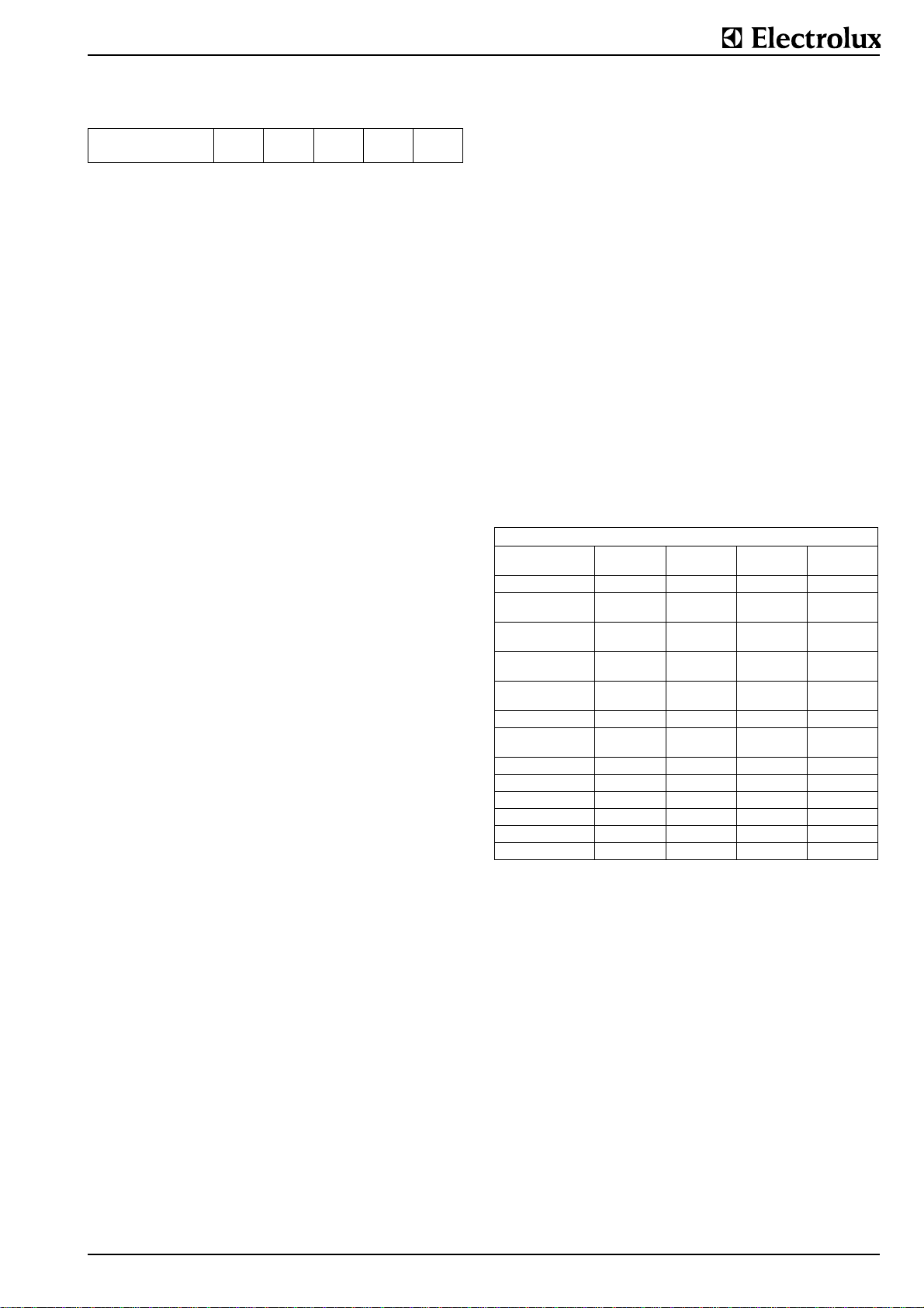
2. TECHNICAL DATA
Tilting boiling pan with jacket heating system.
Electrically heated tilting boiling pans models have water-filled
jackets. Max. working conditions in the jacket: pressure 0.8 bar
(5.8 psi), temperature 244°F (118°C).
Heating-up time: time taken to heat th e pan 100% full o f water
from 68°F (20°C) to 194°F (90°C).
Gas heated tilting boiling pans
.U.C......
080
vessel capacity gal 21.1 26.4 39.4 79.3
Gas heating capacity kW18 21 27 43
Gas heating capacity
btu/h
Natural gas
consumption ft/min
Propan
consumption ft/min
El. power kW 0.2 0.2 0.2 0.2
Voltage ) 120V/1~N,
Amperage A 0.7 0.7 0.7 0.7
Jacket volume dm3 32 38 50 64
Jacket volume gal 8.5 10 13.2 16.9
Water filling lt 17 17 22 30
Water filling gal 3.7 3.7 5.8 7.9
Heating-up time min. 40 45 50 64
61420 71650 92130 146720
1.15 1.34 1.66 2.87
0.44 0.51 0.64 1.1
60Hz
.U.E......
100
120V/1~N,
60Hz
) Voltage for control unit and tilting 230V/1~N*, 50/60 Hz
.U.H......
150
120V/1~N,
60Hz
.U.K......
300
120V/1~N,
60Hz
62.9693.03 Seite 3
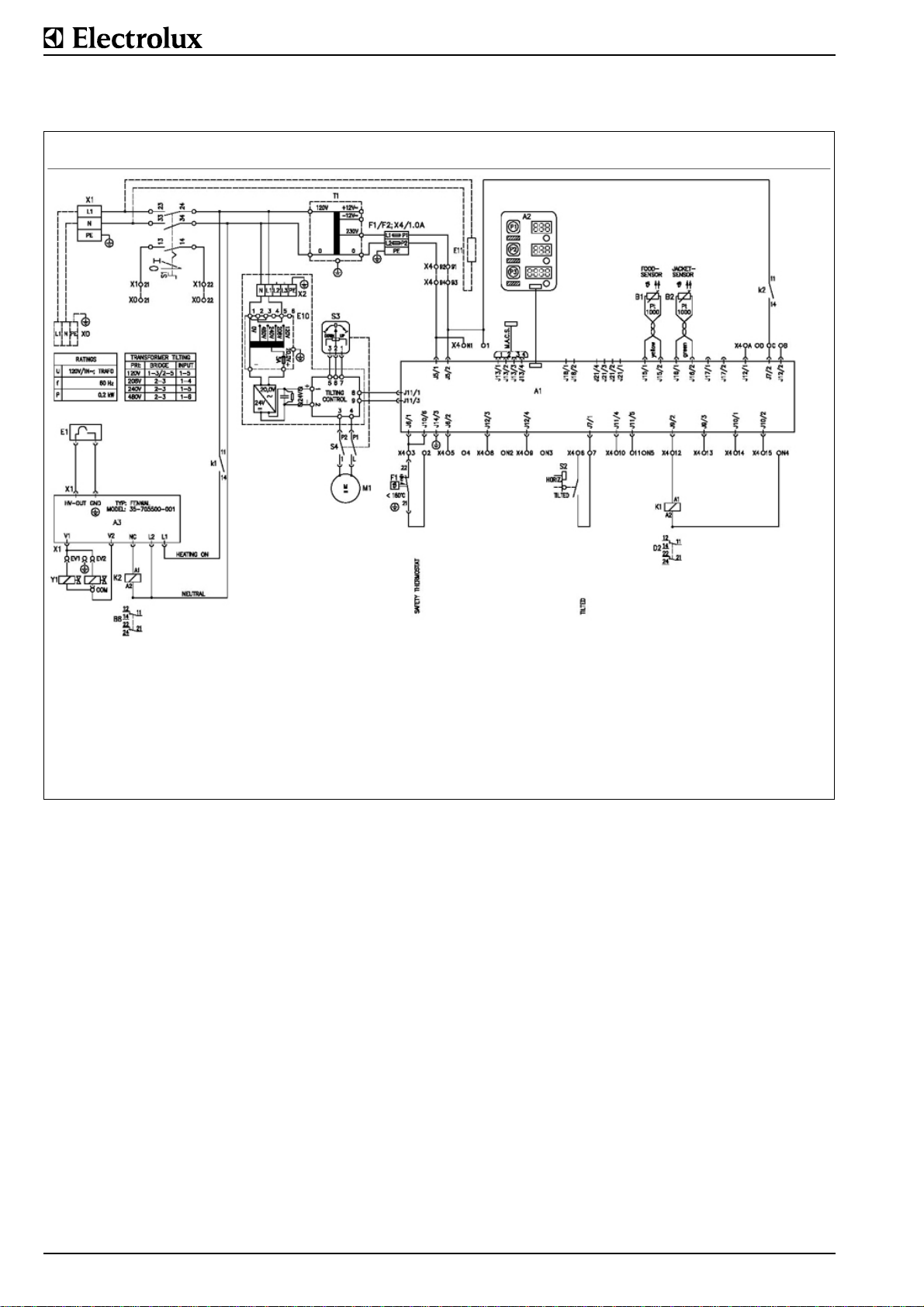
3. ELECTRIC DIAGRAMS
Gas heated tilting boiling pans 80 LT - 150 LT (21.1 gal - 39.4 g al),
120 V:
91.4020
A1 Control board
A2 Operating board
A3 Dungs gas ignitor
B1 Food temperature sensor
B2 Jacket temperature sensor
E1 Electrodes)
E10 Tilting control
E11 Heating resistor
Fig.1 Electric diagram, gas heated tilting boiling pans 80 LT - 150 LT (21.1 gal - 39.4 gal), 120 V
F1 Safety thermostat against lack of
water
K1 Contactor
K2 Contactor
M1 Tilting motor
S1 Control switch
S2 End switch for horizontal position of
the pan
S3 Potentiometer for tilting
X1 Terminals
X4 Control fuse
T1 Single- phase transformer (only for
Y1 Gas valve (SIT 080832 Tandem)
The precise specifications of the individual electric components are given in the corresponding parts list. These must be
used in conjunction with the electrical schematic valid for the
appliance.
voltage unequal 230V)
Seite 4 62.9693.03
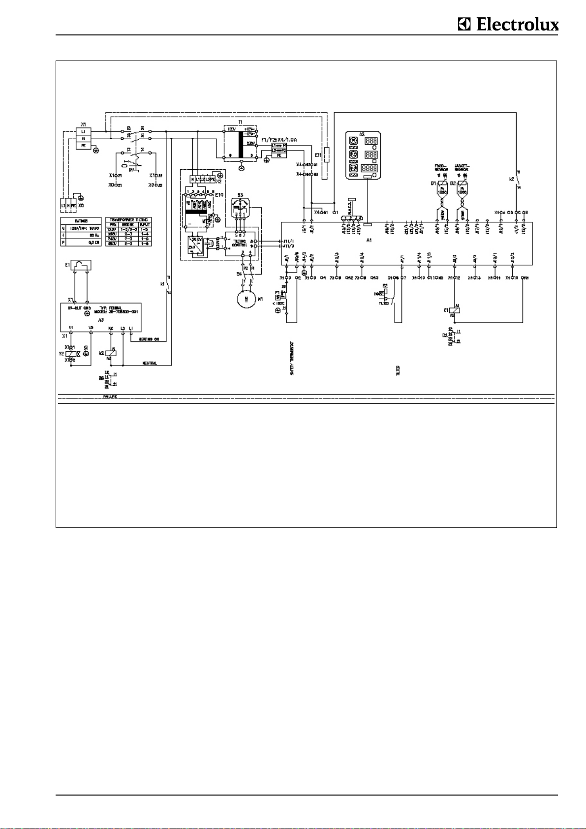
Gas heated tilting boiling pans 300 LT (79.3 gal), 120 V:
91.4018
A1 Control board
A2 Operating board
A3 Dungs gas ignitor
B1 Food temperature sensor
B2 Jacket temperature sensor
E1 Electrodes)
E10 Tilting control
E11 Heating resistor
Fig.2 Electric diagram, gas heated tilting boiling pans 300 LT (79.3 gal), 120 V
F1 Safety thermostat against lack of
water
K1 Contactor
K2 Contactor
M1 Tilting motor
S1 Control switch
S2 End switch for horizontal position of
the pan
The precise specifications of the individual electric components are given in the corresponding parts list. The se must be
used in conjunction with the electrical schematic valid for the
appliance.
S3 Potentiometer for tilting
X1 Terminals
X4 Control fuse
T1 Single-phase transformer (only for
voltage unequal 230V)
Y2 Gas valve (GS-4521-9993)
62.9693.03 Seite 5
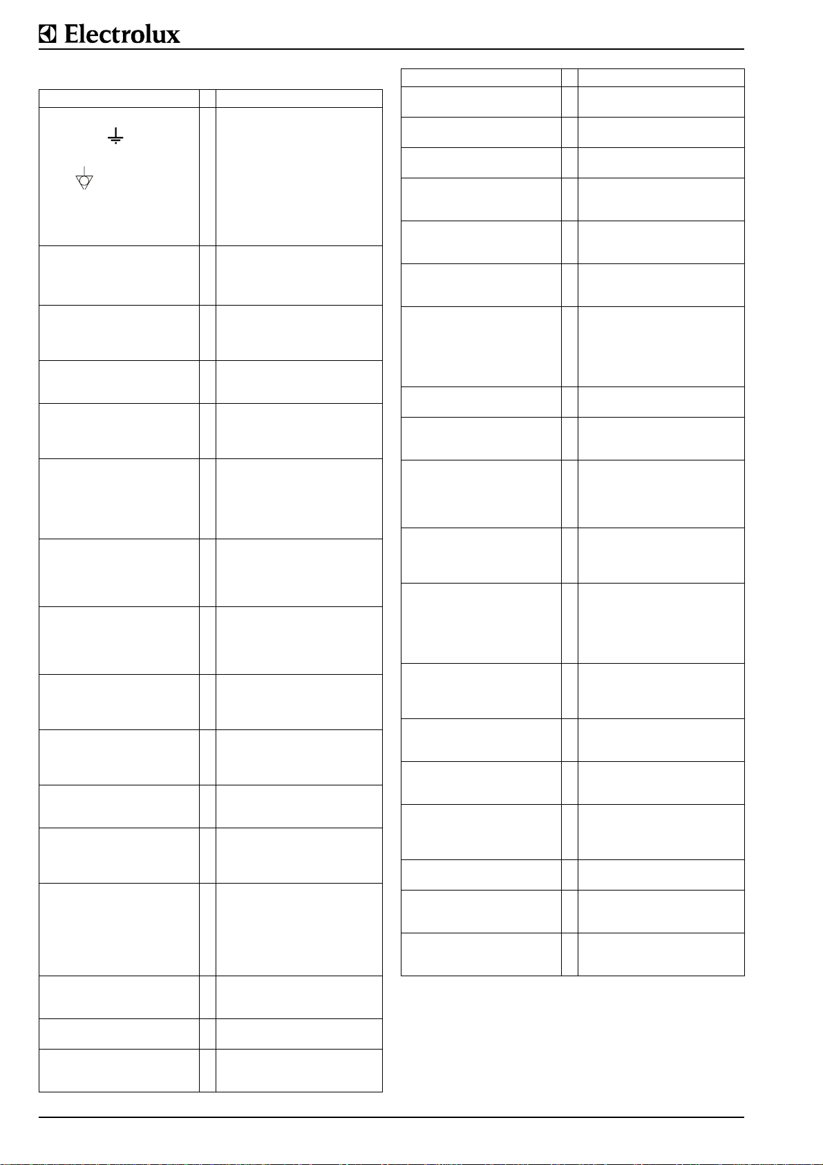
4. MAINTENANCE CHECK LIST
Check Fault D Remedy
Connections for protective
conductors
Connections for equipoten-
tiality
Check that all electric con-
nections and contacts to
terminals, coils, switches
and junctions are tight.
Check relays.
The contacts must move
freely without sticking or
jamming.
Check the burner output,
i.e. measure the preset heating-up time and compare
this with the nominal value.
Clean the diffusor on the
burner. Check its position
and attachment.
Check that the nozzle
(number) is correct. Clean
the area around the nozzle.
Check the distance between the burner and the
pan base.
Visual check of the flame
with a mirror.
Check the condition, the
gap and the attachment
point of the ignition elec-
trode and the earthing
(grounding) electrode.
Check that the gas valve is
not leaking and that it is set
correctly.
Measure the ionization current at the electrodes when
the appliance is at full
power.
Check the high-tension
cable for cracks or brittleness.
Check the plug on the ignition electrode.
Measure the gas pressure
when the appliance is at full
power.
Check condition and leakage of rotation link.
Check that the internal gas
pipes are not leaking.
Ensure that the main gas
tap (if fitted) operates
smoothly and correctly.
In case of loose contacts
D tighten contacts.
In case of defects or faults
D replace contactor or relay.
If this comparison reveals a
deviation of more than 10%
D Clean and check the gas
system.
If its position has changed
D Set the diffusor correctly.
If the nozzle is not the appropriate size ∅, fit the correct
nozzle. If the nozzle is damaged D Fit a new one.
If the actual measurement
deviates more than ± 1mm
from the nominal measurement
D Set the burner distance
exactly.
Flame tips yellow, flame
corona transparent, flames
lift off, flame strikes back
D Clean and set the diffusor
exactly.
If scaling is found, the gap is
not right or the shape has
changed
D Replace.
S If it is leaking
D Replace the valve.
If it is functioning incorrectly
D Readjust it.
If this is outside the recognized tolerance
D Set the electrodes more
accurately.
If any faults are found
D Replace the cables.
If any faults or oxidation are
found
D Replace the high-tension
cables.
In the case of deviations that
are higher than the permissible tolerance
D Send a report to the user
and have the gas pressure
corrected on-site or adapt the
nozzle to the new pressure.
If any faults are found
D replace the parts concerned.
If a leak is found
D Seal the leak.
If the tap is hard to turn
D Regrease the tap or
replace it.
Check Fault D Remedy
Inspect internal wiring. In case of defect cables
Check condition of all ope-
rating foils.
Optical inspection of the
whole control unit.
Test all operating functions
and check that the control
unit works correctly.
Check switches for easy
movement and correct
function.
Compare the food tempe-
rature display with the
actual value.
Inspect fixation and condition of all temperature sen-
sors (jacket, food,
deaeration, excess temperature) and check electrical
connections.
Check the function of the
heating resistance.
Check all elements of the
display on the control panel
with service test 1.
Inspect fixation and condition of all switches (power
isolator, control, tilting, stirrer) and check electrical
connections.
Check function of acoustic
signals.
Check the number of deaerations and thus the water
level in the jacket with parameter PNo. 1.6.5.
Check max. jacket pres-
sure (except on pans with
direct steam heating).
Carry out a leak test of the
jacket (except on pans with
direct steam heating).
Check function of deaera-
tion valve.
Inspect safety valve for
corrosion, damage and leakage. Make function test
and maintenance.
Check the lid for correct
shape or damage.
Check the lid hinges for
correct function.
Check function of mixing
unit for function. Check for
leaks of water connections.
S = Part is relevant for safety
If, during servicing, an increased number of failures is
noted for a part that is relevant for safety, a written report
must be sent to the „Aftersales“ office responsible without
delay
D replace cables.
Defective foils D replace.
S
Defective foils D replace.
S If problems are encountered
D find reason and repair
failure.
If the switch is hard to turn or
makes a noise
D replace.
If the deviation is
D Adjust the display again.
S If sensors, fixation, electrical
connections are found to be
faulty
D replace the parts concerned.
If it is not warm D replace it.
If any element of the display
fails D exchange the whole
operating print.
If defects to any fixation or
electrical connections are
discovered
D replace the parts concerned.
If the sound is off key or no
sound is heard
D exchange the whole control board.
If the number of deaerations
is very high or there is too
little water in the jacket
D refill with demineralized
water and reset the value of
PNo. 1.6.5. to 0.
If it deviates from the max.
reference value
D reset the max. value with
PNo. 1.0.3.
If there is a leak and high
water loss
D locate the leak and seal.
If it is not tight during operation
D clean or replace the valve.
S Clean the valve. If any inad-
missible properties are
encountered
D replace the whole valve.
If irreparably damaged
D replace the lid.
If defective
D disassemble, clean,
grease, adjust the hinge.
If the tap drips or if any pipes
leak
D replace seals.
1°
Seite 6 62.9693.03
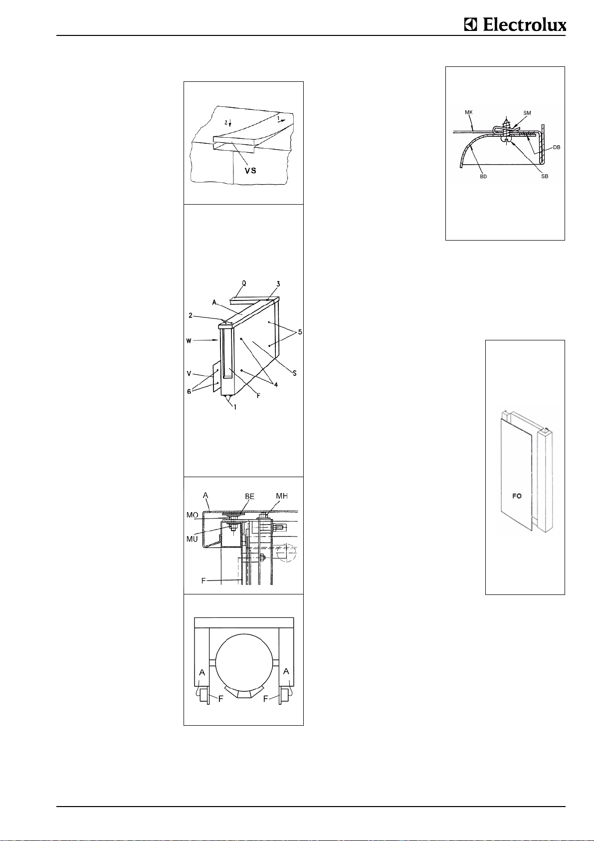
5. ACCESS TO INSIDE
Sheeting of console, support, pan
Remove the connecting rail
(VS)
Loosen the front nuts M6 from
underneath. Bend the rail up
slightly at the front. Pull the rail
out of the appliance.
Switch panel (F) removal:
Unscrew the two screws at
location (1) underneath the
switch panel and the nuts (MH)
at location (2) on the top, pull
out the switch panel at the bottom and then lift up and out of
the fixation. The panel is turned up 90° like a door and
hung at the top on the console.
Cover (A) removal:
If there is a connecting rail
installed to the cover it has to
be removed first. (see 5.3.1.).
Remove the nuts (MU) (two on
a single console, four on a twin
console) at the relevant location (2). Lift the cover at the
front and pull it out of its clip
attachment at the back (3). If a
mixing unit is fitted, this does
not need to be removed from
the cover.
Service panel (V) removal:
Remove the two external nuts
(6) at the front and pull the
panel from its rear attachment
points (5).
Side wall (S) removal:
To remove this, the switch
panel (F) must be removed
first. Remove the nuts (4) and
(5) inside. The upper internal
wall (W) cannot be disassembled. It must be removed and
refitted together with the pan.
The panels are refitted in the
reverse order to that described
above.
Cover (A). The height of the
cover can be levelled by fitting
more or fewer shims (BE) and
tightening the nuts (MH).
Floor mounting on plinth
Hanging the operating panel
(F) on the console
Removing the pan base (BD).
Set the pan in the horizontal
position. Remove the screws
(SB) from underneath and take
out the base (BD) from underneath.
Fitting the base (BD).
Carefully clean any remains of
the old seal from the edge of
the base. Stick a new sealing
strip (DB) on the edge of the
base. Carefully position the
threaded clip (SM) on the jakket (MK). Tighten the screws
(SB).
Pan jacket. The pan jacket is
not removed during normal
servicing work.
6. FUNCTIONAL COMPONENTS
6.1 OPERATING FOIL EXCHANGE Removal
Operating foils (FO) are bonded to the sheet metal surfaces
(cover plates) with self-adhesive coatings. They are removed
with a spatula, a screwdriver or a knife.
Cleaning
The surfaces to which the foil is to be
applied must be clean and dry, i.e., free
from dust, grease, rust, paint, etc. Suitable for cleaning: toluol or 3M article S152 stick remover.
Procedure: shake the can thoroughly and
spray evenly on the surface to be cleaned. (Distance about 5.9 - 7.9“ / 15 - 20
cm.) Rub over with a clean lint-free cloth.
If surfaces are heavily soiled, repeat the
process.
Sticking on the foil
Remove the protective backing, taking
care not to touch the adhesive. After
positioning press down well. It is
important to apply firm, even pressure.
The ideal working temper ature is approxi mately 77°F (25°C). Temperatures below
50°F (10°C) should be avoided since the
adhesive becomes too hard and instantaneous adhesion is reduced. Following
application, the foil has a working temperature range from -40 to +248°F (-40° to
+ 120°C) continuous temperature load
and 356°F (180°C) short-time temperature load.
62.9693.03 Seite 7
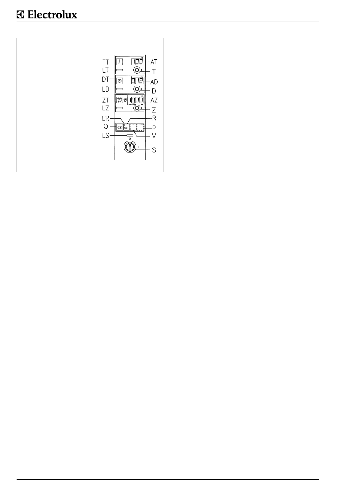
6.2 UNIVERSAL CONTROL
TT Button, activation of settings
LT Lamp, cooking temperature
DT Button, cooking time
LD Lamp, cooking time expires
ZT Button, starting time
LZ Lamp, starting time
LR Lamp, soft settings
Q Button, acoustic signal
R Button, soft
LS Lamp, temperature
pre-setting
AT Display, cooking tempera-
ture
T Temperature selection knob
AD Display, remaining cooking
time
D Cooking time knob
AZ Display, time
Z Starting time knob
S Control switch
The appliances are equipped with a precise state-of-the-art
electronic microprocessor control system with digital preselection of temperature, cooking time and starting time. The control
system can also be remotely controlled using a PC. For control-system operation, please refer to the Operating Instructions.
Temperature setting
If the nominal temperature set on the display (AT) is below the
boiling point of water 207 - 212°F (97 - 100 °C), this temperature will be reached during heating up and then maintained at
this value by the electronic control system and the careful supply of energy. The nominal temperature will not be exceeded
during this process.
When cooking certain products with poor heat conductivity
such as sugar solutions, nominal temperature settings
between 212 and 230°F (100° and 110°C) are required in
order to reach boiling point. The correct setting is largely a
matter of experience.
Setting Power Heating time during
(AT) (%) a period of 120 sec.
L1 12.5 15 sec
L2 12.5 15 sec
L3 25 30 sec
L4 37.5 45 sec
L5 50 60 sec
L6 62.5 75 sec
L7 75 90 sec
L8 87.5 105 sec
L9 100 120 sec
Displays
AT (3 di gits) Temperatures (if all 3 digits light up as well as
the point after the third digit, then this means
that 0.5°F must be added on after the point).
Power settings.
Hold levels.
Parameter number (PNo.).
Parameter value (if all 3 digits light up as well as
a decimal point, then the numeral must be multi-
plied by 1000. E.g. display = 3.99, value =
3990).
Excess pressure in the jacket (test function).
State of the heating system or the valves (if all 3
digits light up as well as a decimal point, then
the numeral must be multiplied by 1000. E.g.
display = 12.3, value = 12300)
Software version.
AD (3 digits) Cooking time
AZ (4 digits) Clock time.
Starting time.
Excess pressure in the jacket (normal function).
6.2.1 PARAMETER PROGRAMMING
General remarks
The same software is used for all appliances which are
equipped with this control system. To ensure that each a ppliance operates as desired, specific parameters must be
entered. The control systems which are installed in the appliances at the factory or are in stock, are equipped with the
microprocessors fitted including the software. The software
contains a default setting (GS) of the parameters (PNo.). The
default setting is selected in such a way that a minimum of
parameters have to be adjusted for the individual setting of the
different appliances. In principle, the corresponding parameters have to be entered for each appliance.
Software version
The microprocessor bears an adhesive label stating the software version and the date. Any change in the software usually
also involves a change in the parameters. Please always
ensure that the version of the parameter list used matches the
software version. The following general rule applies: if the software version has a different number, the parameter list with
the same version must also be used. If the software version
has a different additional letter in the version number (e.g. version 2.51A, version 2.51B, etc.), the parameter list does not
change. Only the number of the version without the additional
letter is important for the parameter list.
Microprocessor (MP)
2 IC insertion sockets are located on the control board. The
large insertion socket for 64 pins accepts the microprocessor.
The software program is located in the ROM (Read Only Memory) of the microprocessor chip. An OTP version (One Time
Programmable) microprocessor is used. This version can only
be written to once and cannot be erased. This mean s that any
program change also means the use of a ne w chip. The old
chip can no longer be used.
EEPROM (EP)
The small insertion socket for 8 pins is for the EEPROM (Electrically Erasable Programmable Read Only Memory). The
parameters are stored in this IC. Once stored, the parameters
remain in this IC even when disconnected from the power supply until they are changed by reprogramming or erased.
Before the parameters are changed for the first time to suit an
appliance, the values for the default setting must be loaded
into the EEPROM. The parameters can be entered in 2 different ways:
Manual input (the more frequent case) and PC input.
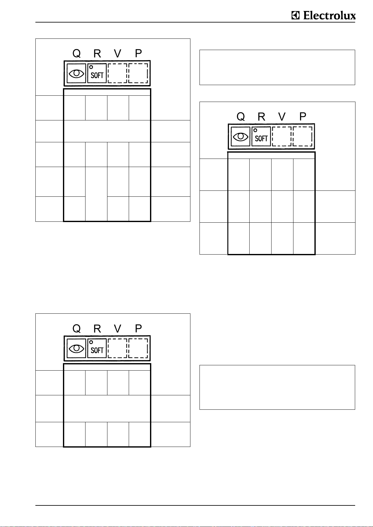
6.2.2 MANUAL PARAMETER INPUT
Default setting (GS) of the parameters
The default setting of the parameters is the same for all appliances which are equipped with this control system. Dependent
on the type of appliance, more or fewer parameters are
required with values that differ from each other to some
degree.
3 of the 4 buttons on the membrane keyboard (Q, R, V a nd P)
are used for the programming of parameters. The 3 buttons
are located in the bottom row on the operating panel. Buttons
V and P are located under the membrane and are not visibly
marked.
Seite 8 62.9693.03
)
Ð
As the same display is used to show the numbers (PNo.) and
the content (X) of the parameters, the following difference is
made between the two figures:
Kind of display (AT): Meaning of display:
with 3 decimal points (e.g.
1.0.3.)
without decimal points (e.g.
126)
Number of parameter PNo
Content (X) of parameter (e.g.
temperature)
Starting position: supply switched off (switch S at 0)
1st
combination
Press and hold
buttons
2nd
combination
Press buttons
3rd
combination
Press buttons
4th
hold
button R
* *
Supply to be switched on (turn switch S to I) Press buttons conti-
* *
*
*
⇓
⇓
*
Waiting time between
the different combinations is 3 seconds
maximum
nuously until the 2nd
beep, then press the
2nd combination
Press buttons continuously until the 2nd
beep, then press the
3rd combination
Hold button R pressed
until the 2nd beep,
then release.
(*)
(*) Display (AT): After "def" is displayed for approx. 2 seconds,
the actual value of the current food temperature will appear.
Display (AZ): Clock time appears (only with process com-
fort control).
The control system program now contains all the default settings for the software version of the microprocessor installed.
Important
which was already in operation is programmed for new, all
parameters which register running times are set to zero.
Parameter-setting (X) specific to each appliance
In order to change the numbers (PNo.) and the content (X) of
the parameters, the same buttons are used as those for entering the default setting.)
Starting position: supply switched off (switch S at 0)
1st
combination
Press and hold
buttons
2nd
Press button
* *
Supply to be switched on (turn switch S to I) Press buttons conti-
Waiting time between
the different combinations is 3 seconds
maximum
nuously until the 2nd
beep, then press 2nd
combination (for the
first time only 1 beep)
Hold button R pressed
until the 2nd beep,
then release.
*
Display (AT): Parameter PNo... 1 appears
Display (AZ): None
The parameter numbers (PNo.) and the values (X) which devi-
ate from the standard setting can now be entered alternately
on the display (AT).
Changing the parameter number (PNo.) and content (X))
Starting position: supply switched off (switch S at 0)
1st
Press button
2nd
Press button
3rd
Press button
*
*
*
Changing
(AT) from:
parameter number
(PNo.) to
parameter content (X)
or vice versa
Increasing the display
entered under 1.
parameter number
(PNo.)
Ï
or parameter content
(X)
Reducing the display
(AT):
parameter number
(PNo.)
or parameter content
(X)
the display
Rate of change of the displays
Increases (button P) or reductions (button Q) can be done at
three different speeds:
• Press the button briefly changes in single steps
• Press the button longer
• at least 1 second the display changes slowly
• press for at least 5 seconds the display changes fast
End of parameter programming
If the content (X) of a parameter (PNo.) is changed, the
changed value is stored when the display (AT) is changed
from parameter content to parameter number using the button
R. The following applies for the last parameter content
changed or if only a parameter content has been changed.
Parameter programming can be finished in 2 ways dependent
on whether the changed value is to be stored or not.:
Finishing: Procedure:
Changed value
to be stored
without decimal
points (e.g. 126)
• Display (AT) shows the parameter number
• Switch off control switch (S)
• Display (AT) shows the parameter value
(X)
• Switch off control switch (S)
6.2.3 PROGRAMMING SPECIFIC APPLIANCE AND
USER DATA
Appliance-specific parameters are only set on the basis of the
type of appliance. User-specific parameters are dependent on
user order, user requirements, siting terms an d are only appliance-dependent to a certain degree.
The parameters are programmed at the factory to the default
setting (GS) if no specific information is given.
New appliance installation
In the case of new appliances, the control system is programmed at the factory to the appliance-specific setting.
62.9693.03 Seite 9
When the appliance is installed at its intended site, the fitter in
charge of installation must set or check the following parameters on the control system. The parameter values are different
for each software version.
PARAMETER SETTINGS
SOFTWARE VERSION BPTH 5.06
PNr.
Parameter
number
GS
Default
setting
Designation
boiling pan,
1 0 Temperature display 1
24 0 Kind of heating 1
29 1 Deaeration sensor of the jacket 0
31 0 HOLD function 1
32 0 HACCP function
without:0
with: 1
54 4 Quantity of switching steps 1
59 2 Regulator hysteresis for double jacket sensor 0.5
63 2 Double jacket sensor lower temperature band 1 1
64 4 Double jacket sensor lower temperature band 2 2
65 6 Double jacket sensor lower temperature band 3 3
66 4 Double jacket sensor upper temperature band 1 2
67 6 Double jacket sensor upper temperature band 2 3
68 8 Double jacket sensor upper temperature band 3 4
78 30 Duration of periods of the power levels 120
79 25 Power level L1 12
83 50
Input of height above sea level of the installation site in 10 m (500 m above sea
level = 50).
X
Opening time of the deaeration valve
85 80
60 liter kettle:
80 - 150 liter kettle:
300 liter kettle:
60
80
120
99 170 Max. jacket pressure to release alarm 180
103 122 Double jacket sensor remappingy-high normal cooking 118
113 115 Double jacket sensor remappingy-high soft cooking 113
116 140 Max. pressure in double jacket 86
157 70 Maximum board temperature 80
Tilting
gas
Seite 10 62.9693.03
 Loading...