

Page 1

JONSERED SERVICE
ENGLISH
FRANÇAIS DEUTSCH
Instruction Manual
English
Manuel d’instructions
Français
Bedienungsanweisung
Deutsch
Manual de instrucciones
Español
Libretto d’Istruzioni
Italiano
Handleiding
Nederlands
Please read these instructions carefully and make
sure you understand them before using this unit.
Avant d’utiliser cet appareil, veuillez lire attentivement les instructions et assurez--vous de les avoir
comprises.
Lesen Sie diese Hinweise zur Handhabung des
Geräts aufmerksam durch. Verwenden Sie es erst,
wenn Sie sicher sind, daß Sie alle Anweisungen
verstanden haben.
Lea atentamente las instrucciones y asegúrese de
entenderlas antes de utilizar este unidad.
Leggere attentamente queste istruzioni e accertarsi
di averle comprese prima di usare l’unità.
Lees deze instructies zorgvuldig en wees er zeker
van dat u ze begrijpt alvorens dit apparaat te gebruiken.
ESPANOL
ITALIANO
NEDERLANDS
530088139
1/10/02
Page 2
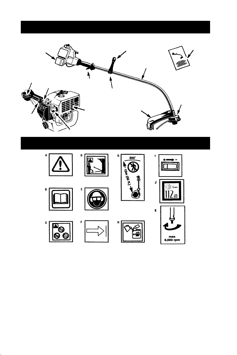
IDENTIFICATION (WHAT IS WHAT?)
Fuel tank
ON/OFF
Switch
Starter
Handle
Choke
Assist handle
Tube
Throttle
Assist handle adjustment
Muffler
Primer Bulb
Shield
IDENTIFICATION OF SYMBOLS
Manual
Trimmer head
WARNING!
A.
serious or even fatal injury.
B. Read and understand the instruction manual before using the trimmer.
C. Never use blades with this tool.
WARNING!
D.
injured. Always wear eye protection.
E. Always use:
Ear protection
Protective glasses or visor
F. Assist handle to be positioned only below the arrow.
G. The operator of the machine must insure that no one comes within a 15 meter radius
while working. When several operators are working within the same area a safety dis-
tance of at least 15 meters must be observed.
H. Use unleaded or quality leaded petrol and two--stroke oil mixed at a ratio of 2.5%.
I. Engine ON/OFF Switch.
J. Sound power level
K. Max speed of output axle, rpm
This trimmer can be dangerous! Careless or improper use can cause
The trimmer line can throw objects violently . You can be blinded or
2
Page 3
SAFETY RULES
WARNING:
appliances, basic safety precautions should always be followed to reduce the risk of fire and
serious injury. Read and follow all instructions.
This power unit can be dangerous! Operator is
responsible for following instructions and warnings on unit and in manual. Read entire instruction manual before using unit! Be thoroughly familiar with the controls and the proper use of the
unit. Restrict the use of this unit to persons who
read, understand, and follow instructions and
warnings on unit and in manual. Never allow
children to operate this unit.
INSTRUCTION
MANUAL
DANGER:
flailing devices. This unit is designed for line
trimmer use only. Use of any other accessories
or attachments will increase the risk of injury.
WARNING:
jects violently. You and others can be blinded/
injured. Wear safety glasses and leg protection. Keep body parts clear of rotating line.
Safety Glasses or similar eye protection
Boots
Keep children, bystanders, and animals 15 meters away. If approached stop unit immediately.
If situations occur which are not covered in
this manual, use care and good judgement. If
you need assistance, contact your authorized
service dealer.
OPERATOR SAFETY
S Dress properly. Always wear safety
glasses or similar eye protection when operating, or performing maintenance, on
your unit (safety glasses are available).
Eye protection should be marked Z87.
S Always wear face or dust mask if operation
is dusty.
S Always wear heavy, long pants, long
sleeves, boots, and gloves. Wearing safety
leg guards is recommended.
When using gardening
SAFETY INFORMATION
ON THE UNIT
Never use blades, wire, or
Trimmer line throws ob-
Hazard Zone
15 meters
S Always wear foot protection. Do not go
barefoot or wear sandals. Stay clear of
spinning line.
S Secure hair above shoulder length. Secure
or remove loose clothing or clothing with
loosely hanging ties, straps, tassels, etc.
They can be caught in moving parts.
S Being fully covered also helps protect you
from debris and pieces of toxic plants
thrown by spinning line.
S Stay Alert. Do not operate this unit when you
are tired, ill, upset or under the influence of alcohol, drugs, or medication. Watch what you
are doing; use common sense.
S Wear hearing protection.
S Never start or run inside a closed room or
building. Breathing exhaust fumes can kill.
S Keep handles free of oil and fuel.
UNIT / MAINTENANCE SAFETY
S Disconnect the spark plug before performing
maintenance except carburetor adjustments.
S Look for and replace damaged or loose
parts before each use. Look for and repair
fuel leaks before use. Keep in good working
condition.
S Replace trimmer head parts that are
chipped, cracked, broken, or damaged in
any other way before using the unit.
S Maintain unit according to recommended
procedures. Keep cutting line at proper
length.
S Use only 1,6 mm diameter Jonsered!
brand line. Never use wire, rope, string,
etc.
S Install required shield properly before using
the unit. Use only specified trimmer head;
make sure it is properly installed and securely fastened.
S Make sure unit is assembled correctly as
shown in this manual.
S Make carburetor adjustments with lower
end supported to prevent line from contacting any object.
S Keep others away when making carburetor
adjustments.
S Use only recommended Jonsered! acces-
sories and replacement parts.
S Have all maintenance and service not ex-
plained in this manual performed by an authorized service dealer.
FUEL SAFETY
S Mix and pour fuel outdoors.
S Keep away from sparks or flames.
S Use a container approved for fuel.
S Do not smoke or allow smoking near fuel or
the unit.
S Avoid spilling fuel or oil. Wipe up all fuel spills.
S Move at least 3 meters away from fueling
site before starting engine.
S Stop engine and allow to cool before re-
moving fuel cap.
S Always store gasoline in a container ap-
proved for flammable liquids.
3
Page 4
CUTTING SAFETY
WARNING:
each use. Remove objects (rocks, broken
glass, nails, wire, etc.) which can be thrown
by or become entangled in line. Hard objects
can damage the trimmer head and be thrown
causing serious injury.
S Use only for trimming, scalping, mowing
and sweeping. Do not use for edging, pruning or hedge trimming.
S Keep firm footing and balance. Do not over-
reach.
S Keep all parts of your body away from muf-
fler and spinning line. Keep engine below
waist level. A hot muffler can cause serious
burns.
S Cut from your right to your left. Cutting on
left side of the shield will throw debris away
from the operator.
S Use only in daylight or good artificial light.
S Use only for jobs explained in this manual.
Inspect the area before
TRANSPORTING AND STORAGE
S Allow the engine to cool; secure unit before
storing or transporting in vehicle.
S Empty fuel tank before storing or transport-
ing the unit. Use up fuel left in the carburetor
by starting engine and letting it run until it
stops.
ASSEMBLY
S Store unit and fuel in an area where fuel va-
pors cannot reach sparks or open flames
from water heaters, electric motors or
switches, furnaces, etc.
S Store unit so line limiter cannot accidentally
cause injury. Unit can be hung by the tube.
S Store the unit out of the reach of children
SPECIAL NOTICE:
tions through prolonged use of gasoline powered hand tools could cause blood vessel or
nerve damage in the fingers, hands, and
joints of people prone to circulation disorders
or abnormal swellings. Prolonged use in cold
weather has been linked to blood vessel damage in otherwise healthy people. If symptoms
occur such as numbness, pain, loss of
strength, change in skin color or texture, or
loss of feeling in the fingers, hands, or joints,
discontinue the use of this tool and seek medical attention. An anti-vibration system does
not guarantee the avoidance of these problems. Users who operate power tools on a
continual and regular basis must monitor
closely their physical condition and the condition of this tool.
Exposure to vibra-
WARNING:
ly assembled and all fasteners are secure.
Examine parts for damage. Do not use damaged parts.
It is normal for the fuel filter to rattle in the
empty fuel tank.
Finding fuel or oil residue on muffler is normal
due to carburetor adjustments and testing
done by the manufacturer .
Make sure unit is proper-
ADJUSTING THE HANDLE
WARNING:
dle, be sure it remains between the trigger
and the safety label. Assist handle must be
positioned only below the arrow.
1. Loosen knob on handle.
2. Rotate the handle on the tube to an upright position; retighten knob.
When adjusting the han-
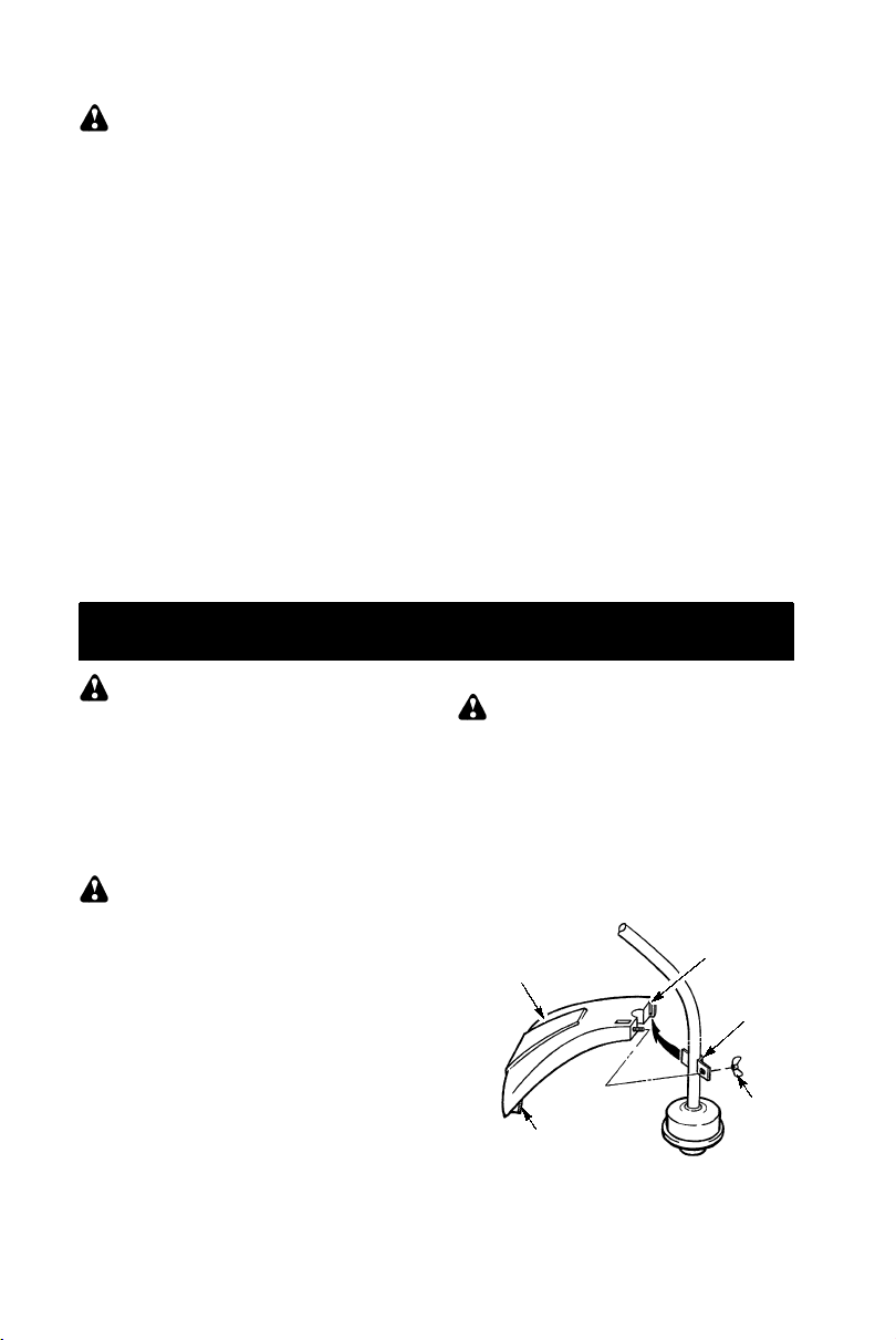
ATTACHING THE SHIELD
WARNING:
erly installed. The shield provides partial
protection from the risk of thrown objects to
the operator and others and is equipped with
a line limiter which cuts excess line. The line
limiter (on underside of shield) is sharp and
can cut you.
1. Remove wing nut from shield.
2. Insert bracket into slot on shield.
3. Pivot shield until bolt passes through hole
in bracket.
4. Reinstall wing nut and tighten securely.
Shield
Line Limiter Blade
4
The shield must be prop-
Slot
Bracket
Wing
Nut
Page 5

OPERATION
WARNING:
information in the safety rules before you begin. If you do not understand the safety rules,
do not attempt to fuel your unit. Contact an
authorized service dealer.
Be sure to read the fuel
FUELING ENGINE
WARNING:
when refueling.
This engine is certified to operate on un-
leaded gasoline. Before operation, gasoline
must be mixed with a good quality synthetic
2-cycle air-cooled engine oil designed to be
mixed at a ratio of 40:1 (2.5%). A 40:1 ratio is
obtained by mixing 5 liters of unleaded gasoline with 0,125 liter of oil. DO NOT USE automotive oil or boat oil. These oils will cause engine damage. When mixing fuel, follow
instructions printed on oil container. Once oil
is added to gasoline, shake container momentarily to assure that the fuel is thoroughly
mixed. Always read and follow the safety
rules relating to fuel before fueling your unit.
Remove fuel cap slowly
IMPORTANT
Experience indicates that alcohol blended
fuels (called gasohol or using ethanol or
methanol) can attract moisture which leads to
separation and formation of acids during storage. Acidic gas can damage the fuel system
of an engine while in storage. To avoid engine
problems, empty the fuel system before storage for 30 days or longer. Drain the gas tank,
start the engine and let it run until the fuel lines
and carburetor are empty. Use fresh fuel next
season. Never use engine or carburetor
cleaner products in the fuel tank or permanent
damage may occur.
HOW TO STOP YOUR UNIT
S T o stop the engine, move the ON/OFF
switch to the OFF position.
HOW TO START YOUR UNIT
WARNING:
turn while starting the engine. Avoid any contact with the muffler. A hot muffler can cause
serious burns.
The trimmer head will
ST ARTING A COLD ENGINE (or a
warm engine after running out of fuel)
Starting Position
Starter Handle
Choke
Lever
Primer Bulb
1. Set unit on a flat surface.
2. Move ON/OFF switch to the ON position.
3. Slowly press the primer bulb 6 times.
4. Move choke lever to FULL CHOKE position.
5. Squeeze and hold trigger through all re-
maining steps.
6. Pull starter rope handle sharply until engine sounds as if it is trying to start, but do
not pull rope more than 6 times.
7. As soon as engine sounds as if it is trying
to start, move choke lever to HALF
CHOKE.
8. Pull starter rope sharply until engine runs,
but no more than 6 pulls. If the engine
doesn’t start after 6 pulls (at the HALF
CHOKE position), move the choke lever
to the FULL CHOKE position and press
the primer bulb 6 times. Squeeze and hold
the throttle trigger and pull the starter rope
2 more times. Move the choke lever to the
HALF CHOKE position and pull the starter rope until the engine runs, but no more
than 6 pulls.
NOTE:
probably flooded. Proceed to STARTING
A FLOODED ENGINE.
9. Once the engine starts, allow it to run 10
seconds, then move the choke lever to
OFF CHOKE. Allow the unit to run for 30
more seconds at OFF CHOKE before releasing the throttle trigger.
NOTE:
ver in the OFF CHOKE position, move the
choke lever to the HALF CHOKE position
and pull the rope until engine runs, but no
more than 6 pulls.
If engine still doesn’t start, it is
If engine dies with the choke le-
Muffler
STARTING A WARM ENGINE
1. Move ON/OFF switch to the ON position.
2. Move the choke lever to the HALF
CHOKE position.
3. Squeeze and hold the throttle trigger.
Keep throttle trigger fully squeezed until
the engine runs smoothly.
4. Pull starter rope sharply until engine runs,
but no more than 5 pulls.
5. Allow engine to run 15 seconds, then
move the choke lever to the OFF CHOKE
position.
5
Page 6

NOTE:
rope 5 more pulls. If engine still does not run, it
is probably flooded.
If engine has not started, pull starter
STARTING A FLOODED ENGINE
Flooded engines can be started by placing
the choke lever in the OFF CHOKE position;
then, pull the rope to clear the engine of excess fuel. This could require pulling the starter
handle many times depending on how badly
the unit is flooded.
If the unit still doesn’t start, refer to TROUBLESHOOTING TABLE.
OPERATING INSTRUCTIONS
OPERATING POSITION
ALWAYS WEAR:
Eye Protection
CUTTING METHODS
WARNING:
do not crowd the line when cutting around
hard objects (rock, gravel, fence posts, etc.),
which can damage the trimmer head, become
entangled in the line, or be thrown causing a
serious hazard.
S The tip of the line does the cutting. You will
achieve the best performance and minimum line wear by not crowding the line into
the cutting area. The right and wrong ways
are shown below.
Tip of the Line
Does The Cutting
Use minimum speed and
Line Crowded Into
Work Area
Long Pants
Heavy Shoes
Cut from your right to your left.
WARNING:
tion and hearing protection. Never lean over
the trimmer head. Rocks or debris can ricochet or be thrown into eyes and face and
cause blindness or other serious injury.
Do not run the engine at a higher speed than
necessary. The cutting line will cut efficiently
when the engine is run at less than full throttle.
At lower speeds, there is less engine noise and
vibration. The cutting line will last longer and will
be less likely to “weld” onto the spool.
Always release the throttle trigger and allow the
engine to return to idle speed when not cutting.
To stop engine:
S Release the throttle trigger.
S Move the ON/OFF switch to the OFF posi-
tion.
Always wear eye protec-
TRIMMER LINE ADVANCE
Advance line by tapping the bottom of the cutting head lightly on the ground while engine is
running at full speed. The metal line limiter
blade attached to the guard will cut the line to
the proper length.
WARNING:
ter line. Other sizes and shapes of line will not
advance properly and will result in improper
cutting head function or can cause serious
injury. Do not use other materials such as
wire, string, rope, etc. Wire can break off during cutting and become a dangerous missile
that can cause serious injury.
Use only 1,6 mm diame-
Right Wrong
S The line will easily remove grass and
weeds from around walls, fences, trees and
flower beds, but it also can cut the tender
bark of trees or shrubs and scar fences.
S For trimming or scalping, use less than full
throttle to increase line life and decrease
head wear, especially:
S During light duty cutting.
S Near objects around which the line can-
wrap such as small posts, trees or fence
wire.
S For mowing or sweeping, use full throttle for
a good clean job.
TRIMMING -- Hold the bottom of the trimmer
head about 80 mm above the ground and at
an angle. Allow only the tip of the line to make
contact. Do not force trimmer line into work
area.
Trimming
3in.(8cm)
Above Ground
SCALPING -- The scalping technique removes unwanted vegetation. Hold the bottom
of the trimmer head about 80 mm above the
ground and at an angle. Allow the tip of the line
to strike the ground around trees, posts,
monuments, etc. This technique increases
line wear.
Scalping
6
Page 7

MOWING -- Your trimmer is ideal for mowing
in places conventional lawn mowers cannot
reach. In the mowing position, keep the line
parallel to the ground. Avoid pressing the
head into the ground as this can scalp the
ground and damage the tool.
Mowing
MAINTENANCE
SWEEPING -- The fanning action of the rotating line can be used for a quick and easy
clean up. Keep the line parallel to and above
the surfaces being swept and move the tool
from side to side.
Sweeping
WARNING:
plug before performing maintenance except
for carburetor adjustments.
Disconnect the spark
CHECK FOR LOOSE
FASTENERS AND PARTS
S Spark Plug Boot
S Air Filter
S Housing Screws
S Assist Handle Screw
S Debris Shield
CHECK FOR DAMAGED OR
WORN PARTS
Contact an authorized service dealer for replacement of damaged or worn parts.
S ON/OFF Switch -- Ensure ON/OFF switch
functions properly by moving the switch to
the OFF position. Make sure engine stops;
then restart engine and continue.
S Fuel Tank -- Discontinue use of unit if fuel
tank shows signs of damage or leaks.
S Debris Shield -- Discontinue use of unit if
debris shield is damaged.
INSPECT AND CLEAN UNIT AND
LABELS
S After each use, inspect complete unit for
loose or damaged parts. Clean the unit and
labels using a damp cloth with a mild detergent.
S Wipe off unit with a clean dry cloth.
CLEAN AIR FILTER
A dirty air filter decreases engine performance and increases fuel consumption and
harmful emissions. Always clean after every
5 hours of operation.
1. Clean the cover and the area around it to
keep dirt from falling into the carburetor
chamber when the cover is removed.
2. Remove parts as illustrated.
NOTE:
flammable solvent to avoid creating a fire hazard or producing harmful evaporative emissions.
3. Wash the filter in soap and water.
4. Allow filter to dry.
5. Add a few drops of oil to the filter; squeeze
6. Replace parts.
Do not clean filter in gasoline or other
the filter to distribute oil.
Air Filter
Air Filter
Cover
Screws
REPLACE SPARK PLUG
Replace the spark plug each year to ensure
the engine starts easier and runs better. Set
spark plug gap at 0,6 mm. Ignition timing is
fixed and nonadjustable.
1. Twist, then pull off spark plug boot.
2. Remove spark plug from cylinder and discard.
3. Replace with Champion RCJ-6Y spark
plug and tighten securely with a 19 mm
socket wrench.
4. Reinstall the spark plug boot.
7
Page 8

SERVICE AND ADJUSTMENTS
REPLACING THE LINE
1. Move the ON/OFF switch to the OFF
position.
2. Disconnect the spark plug lead wire.
3. Remove spool by firmly pulling on tap button. Clean entire surface of hub and
spool. Replace with a pre-wound spool, or
cut a length of 6 meters of 1,6 mm diameter line.
WARNING:
string, etc., which can break off and become a
dangerous missile.
4. Insert one end of the line about 1 cm into
the small hole on the inside of spool.
Small
Hole
Line in
Notch
Never use wire, rope,
Spool
Hub
Line exit hole
STORAGE
WARNING:
steps after each use:
S Allow engine to cool before storing or trans-
porting.
S Store unit and fuel in a well ventilated area
where fuel vapors cannot reach sparks or
open flames from water heaters, electric
motors or switches, furnaces, etc.
S Empty fuel tank before storing or transport-
ing the unit.
S Store unit and fuel well out of the reach of
children.
S Store unit with all guards in place. Position
unit so that any sharp object cannot accidentally cause injury.
SEASONAL STORAGE
Prepare unit for storage at end of season or if
it will not be used for 30 days or more.
If your unit is to be stored for a period of time:
S Clean the entire unit before lengthy stor-
age.
S Store in a clean dry area.
S Lightly oil external metal surfaces.
Perform the following
5. Wind the line evenly and tightly onto the
spool. Wind in the direction of the arrow
found on the spool.
6. Push the line into the notch, leaving 7 -- 12
cm unwound.
7. Insert the line into the the exit hole in the
hub as shown in the illustration.
8. Align the notch with the line exit hole.
9. Push spool into hub until it snaps into
place.
10. Pull the line extending outside of the hub
to release it from the notch.
CARBURETOR ADJUSTMENT
Your carburetor is equipped with limiter caps.
Damage will occur if you turn the needles beyond the limiter stops. Carburetor adjustment
is a complicated task. We recommend that
you take your unit to an authorized service
dealer.
ENGINE
S Remove spark plug and pour 1 teaspoon of
40:1, 2-cycle engine oil (air cooled) through
the spark plug opening. Slowly pull the
starter rope 8 to 10 times to distribute oil.
S Replace spark plug with new one of recom-
mended type and heat range.
S Clean air filter.
S Check entire unit for loose screws, nuts,
and bolts. Replace any damaged, broken,
or worn parts.
S At the beginning of the next season, use
only fresh fuel having the proper gasoline to
oil ratio.
OTHER
S Do not store gasoline from one season to
another.
S Replace your gasoline can if it starts to rust.
8
Page 9

TROUBLESHOOTING TABLE
WARNING:
recommended remedies below except remedies that require operation of the unit.
Always stop unit and disconnect spark plug before performing all of the
TROUBLE CAUSE REMEDY
Engine will not
start.
Engine will
not idle
properly.
Engine will not
accelerate,
lacks power,
or dies under
a load.
Engine
smokes
excessively.
Engine runs
hot.
1. ON/OFF switch in OFF
position.
2. Engine flooded.
3. Fuel tank empty.
4. Spark plug not firing.
5. Fuel not reaching
carburetor.
6. Carburetor requires
adjustment.
1. Carburetor requires
adjustment.
2. Crankshaft seals worn.
3. Compression low.
1. Air filter dirty.
2. Spark plug fouled.
3. Carburetor requires
adjustment.
4. Carbon build-up on
muffler outlet screen.
5. Compression low.
1. Choke partially on.
2. Fuel mixture incorrect.
3. Air filter dirty.
4. Carburetor requires
adjustment.
1. Fuel mixture incorrect.
2. Spark plug incorrect.
3. Carburetor requires
adjustment.
4. Carbon build-up on
muffler outlet screen.
1. Move ON/OFF switch to ON position.
2. See “Starting a Flooded Engine” in
Operation Section.
3. Fill tank with correct fuel mixture.
4. Install new spark plug.
5. Check for dirty fuel filter; replace.
Check for kinked or split fuel line;
repair or replace.
6. See “Carburetor Adjustment” in
Service and Adjustments Section.
1. See “Carburetor Adjustment” in
Service and Adjustments Section.
2. Contact an authorized service dealer.
3. Contact an authorized service dealer.
1. Clean or replace air filter.
2. Clean or replace plug
and regap.
3. See “Carburetor Adjustment” in
Service and Adjustments Section.
4. Contact an authorized service dealer.
5. Contact an authorized service dealer.
1. Adjust choke.
2. Empty fuel tank and refill with
correct fuel mixture.
3. Clean or replace air filter.
4. See “Carburetor Adjustment” in
Service and Adjustments Section.
1. Empty fuel tank and refill with
correct fuel mixture.
2. Replace with correct spark plug.
3. See “Carburetor Adjustment” in
Service and Adjustments Section.
4. Contact an authorized service dealer.
U.S. EPA / ENVIRONMENT CANADA
EMISSION CONTROL WARRANTY STATEMENT
YOUR WARRANTY RIGHTS AND OBLIGATIONS:
Agency, Environment Canada and Jonsered
are pleased to explain the emissions control
system warranty on your year 2001--2004 small
off--road engine. Jonsered must warrant the
emission control system on your small off--road
engine for the periods of time listed below provided there has been no abuse, neglect, or improper maintenance of your small off--road engine. Your emission control system includes
parts such as the carburetor and the ignition
system. Where a warrantable condition exists,
Jonsered will repair your small off--road engine
The U. S. Environmental Protection
at no cost to you. Expenses covered under warranty include diagnosis, parts and labor.
MANUFACTURER’S WARRANTY COVERAGE:
If any emissions related part on your engine (as listed under Emissions Control Warranty Parts List) is defective or a defect in the
materials or workmanship of the engine causes
the failure of such an emission related part, the
part will be repaired or replaced by Jonsered.
OWNER’S WARRANTY RESPONSIBILITIES:
As the small off--road engine owner, you
are responsible for the performance of the required maintenance listed in your instruction
manual. Jonsered recommends that you retain
9
Page 10

all receipts covering maintenance on your small
off--road engine, but Jonsered cannot deny warranty solely for the lack of receipts or for your
failure to ensure the performance of all scheduled maintenance. As the small off- -road engine owner, you should be aware that Jonsered
may deny you warranty coverage if your small
off--road engine or a part of it has failed due to
abuse, neglect, improper maintenance, unapproved modifications, or the use of parts not
made or approved by the original equipment
manufacturer. You are responsible for presenting your small off--road engine to a Jonsered authorized repair center as soon as a problem exists. Warranty repairs should be completed in a
reasonable amount of time, not to exceed 30
days. If you have any questions regarding your
warranty rights and responsibilities, you should
contact your nearest authorized service center
or call Jonsered at 1--916--383--3511.
RANTY COMMENCEMENT DATE:
WAR -
The warranty period begins on the date the small off-road engine is purchased.
COVERAGE:
This warranty shall be for a peri-
LENGTH OF
od of two years from the initial date of purchase.
WHAT IS COVERED: REP AIR OR REPLACEMENT OF PARTS.
Repair or replacement of any warranted part will be performed at
no charge to the owner at an approved Jonsered servicing center. If you have any questions
regarding your warranty rights and responsibilities, you should contact your nearest authorized
service c enter or call Jonser ed at
1--916 --383--3511.
WARRANTY PERIOD:
Any
warranted part which is not scheduled for replacement as required maintenance, or which is
scheduled only for regular inspection to the effect of ”repair or replace as necessary” shall be
warranted for 2 years. Any warranted part which
is scheduled for replacement as required main-
tenance shall be warranted for the period of time
up to the first scheduled replacement point for
that part.
DIAGNOSIS:
The owner shall not be
charged for diagnostic labor which leads to the
determination that a warranted part is defective
if the diagnostic work is performed at an approved Jonsered servicing center.
QUENTIAL DAMAGES:
Jonsered may be li-
CONSE-
able for damages to other engine components
caused by the failure of a warranted part still under warranty.
WHAT IS NOT COVERED:
All
failures caused by abuse, neglect, or improper
maintenance are not covered.
MODIFIED PARTS:
The use of add- -on or
ADD--ON OR
modified parts can be grounds for disallowing a
warranty claim. Jonsered is not liable to cover
failures of warranted parts caused by the use of
add--on or modified parts.
CLAIM:
If you have any questions regarding
HOW TO FILE A
your warranty rights and responsibilities, you
should contact your nearest authorized service
center or call Jonsered at 1--916--383 --3511.
WHERE TO GET WARRANTY SERVICE:
Warranty services or repairs shall be provided
at all Jonsered service centers. Call
1--916 --383--3511.
MAINTENANCE, REPLACEMENT AND REPAIR OF EMISSION
RELATED PARTS:
Any Jonsered approved
replacement part used in the performance of
any warranty maintenance or repair on emission related parts will be provided without
charge to the owner if the part is under warranty.
EMISSION CONTROL WARRANTY PARTS
LIST:
Carburetor, Ignition System: Spark Plug
(covered up to maintenance schedule), Ignition
Module.
MAINTENANCE STATEMENT:
The
owner is responsible for the performance of all
required maintenance as defined in the instruction manual.
The information on the product label indicates which standard your engine is certified.
Example: (Year) EPA Phase 1 or Phase 2 and/or CALIFORNIA.
10
Page 11

This engine is certified to be emissions compliant for the following use:
Moderate (50 hours)
Intermediate (125 hours)
Extended (300 hours)
DECLARATION OF CONFORMITY
relating to 2000/14/EC
EU Declaration of Conformity relating to 2000/14/EC
Poulan/Weed Eater, Division Electrolux North America, Inc.,
We,
75501, USA, Tél. : +1 903 223 4100, declare under sole responsibility that the
model GT21L grass trimmer
DIRECTIVE and from serial numbers 2001--305N00001 and onwards, conforms to the
provisions of the DIRECTIVE. The cutting width is 431 mm. The measured sound power
is 105,8 dB and the guaranteed sound power is 112 dB.
Texarkana 01--12--17
was assessed in accordance with Annex V of the
Michael S. Bounds, Director
Product Safety and Standards
Texarkana, TX,
Jonsered
DECLARATION OF CONFORMITY
relating to 98/37/EC
EU Declaration of Conformity
Europe)
Poulan/Weed Eater, Division Electrolux North America, Inc.,
We,
75501, USA, Tél. : +1 903 223 4100, Declare under sole responsibility that the
model GT21L
the provisions of the DIRECTIVES :
(electromagnetic compatibility),including amendments and is in conformity with the
following standards:
SMP, The Swedish Machinery Testing Institute,
Sweden, has carried out voluntary type approval. The certificate(s) are numbered:
SEC/95/115
Texarkana 01--12--17
grass trimmer from serial numbers 2001--305N00001 and onwards, follows
EN 292--2, prEN 31806
.
(Directive 98/37/EC, Annex II, A) (Only applies to
Texarkana, TX,
Jonsered
98/37/EC
and
(machinery) and
CISPR 12.
Fyrisborgsgatan 3 S-- 754 50 Uppsala,
89/336/EEC
Michael S. Bounds, Director
Product Safety and Standards
11
Page 12

TECHNICAL DATA SHEET
M
ODEL: GT21L
ENGINE AND FUEL SYSTEM
Displacement 21 cm
Idling speed 3700 rpm
Maximum engine power, measured in accordance with ISO 8893 0,4 kW/8000 rpm
Fuel tank volume capacity 0.34 liter
WEIGHT
Without cutting attachment or guard, empty tank 3,4 Kg
CUTTING ATTACHMENT
Type, diameter for trimmer head 84 mm
SOUND LEVELS
SOUND PRESSURE LEVELS measured in accordance with ISO 7917
Idling 85 dB(A)
Racing 95 dB(A)
SOUND POWER LEVELS measured in accordance with ISO 10884
Idling 93 dB(A)
Racing 105,8 dB(A)
VIBRATION LEVELS
FRONT HANDLE
Idling 2,9 m/s
Racing 14,1 m/s
REAR HANDLE
Idling 4,1 m/s
Racing 7,7 m/s
measured in accordance with ISO 7916
3
2
2
2
2
YEAR OF CONSTRUCTION:
MANUFACTURER’S ADDRESS:
2002
Jonsered
SE--561 82 Huskvarna
Huskvarna, Sweden
12
 Loading...